ZEOPF99BALLASTBallast
Gain International Enterprise Limited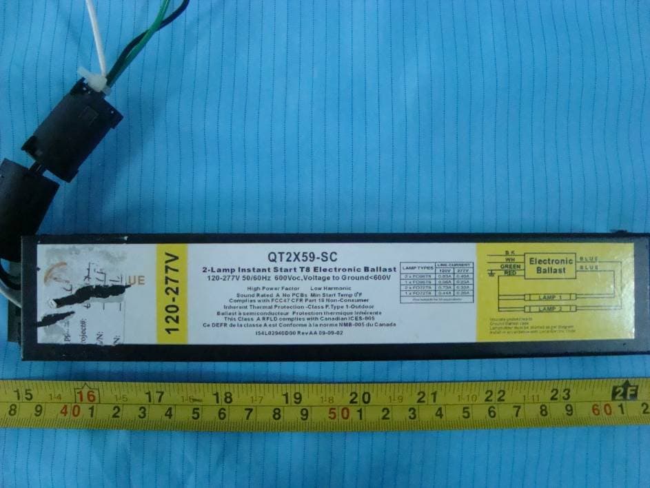
Click to zoom
Application Details
- Equipment Class
- 8CC - Part 18 Consumer Device
- Date of Grant
- May 05, 2011
- Application Purpose
- Original Equipment
- Date of Application
- May 05, 2011
- Equipment Note
- Ballast
- Frequency Range
- 0.04000000 - 0.05000000
- Country
- Hong Kong
Documents & Files
Document Text
Text extracted from the exhibit documents filed with the FCC. Open a document above to read the original.
Users Manual
USER MANUAL 1、 Use on AC 120-277V, 50-60Hz, never use on ±5% or other voltage. 2、 Environment temperature -10~+50 0 C, Installation site should not be corrosive, flammable, easy violent gas and severe vibration environment. 3 、 See the labels of the products installed void take the line to prevent errors and configuration to control damage to the device with the ballast. 4、Never use for no waterproof device outdoor environment. 5、Never used with dimmer and frequent on and off. 6 、 Prohibited in the rain, completely sealed, insulated vessels in use. 7、Never disassemble or modify-any changes could void the user’s authority to operate this device. 8、This product could produce interference when used near a TV, Radio, Wireless remote control or maritime safety communications equipment or other critical navigation or communication equipment operating between 0.45-30MHz.Of interference should occur, move the lamp away from the appliance a distance of three feet or more, Or, Plug the ballast or the appliance into a different outlet. 9、Warning: This device complies with Part 18 of FCC rules.
External Photos
EXHIBIT B - EUT EXTERNAL PHOTOGRAPHS Model: QT2X32-SC/YD2X32-SC EUT – Top View EUT – Bottom View Model: QT3X32-SC/YD3X32-SC EUT – Top View EUT – Bottom View Model: QT4X32-SC/YD4X32-SC EUT – Top View EUT – Bottom View Model: QT2X59-SC/YD2X59-SC EUT – Top View EUT – Bottom View
ID Label/Location Info
EXHIBIT A - FCC ID LABEL AND LOCATION FCC ID Label and Loaction
Internal Photos
EXHIBIT C - EUT INTERNAL PHOTOGRAPHS Model: QT2X32-SC/YD2X32-SC EUT – Cover off View EUT – Mainboard Top View EUT – Main Board Bottom View Model: QT3X32-SC/YD3X32-SC EUT – Cover off View EUT – Mainboard Top View EUT – Main Board Bottom View Model: QT4X32-SC/YD4X32-SC EUT – Cover off View EUT – Mainboard Top View EUT – Main Board Bottom View Model: QT2X59-SC/YD2X59-SC EUT – Cover off View EUT – Mainboard Top View EUT – Main Board Bottom View
Test Report
Note: This test report is prepared for the customer shown above and for the device described herein. It may not be duplicated or used in part without prior written consent from Bay Area Compliance Laboratories Corp. This report must not be used by the customer to claim product certification, approval, or endorsement by NVLAP*, or any agency of the Federal Government. * This report contains data that are not covered by the NVLAP accreditation and are marked with an asterisk “★” (Rev.2) FCC PART 18 MEASUREMENT AND TEST REPORT For Gain International Enterprise Limited Flat/Room 2006, 20/F, Tung Chun Commercial Centre 438-444, Shanghai Street, Mongkok, Kowloon, Hong Kong FCC ID: ZEOPF99BALLAST Report Type: Original Report Product Type: Ballast Test Engineer: Phase Zhang Report Number: RSZ10120252 Report Date: 2011-03-25 Reviewed By: Lisa Zhu EMC Engineer Prepared By: Bay Area Compliance Laboratories Corp. (Shenzhen) 6/F, the 3rd Phase of WanLi Industrial Building, ShiHua Road, FuTian Free Trade Zone Shenzhen, Guangdong,China Tel: +86-755-33320018 Fax: +86-755-33320008 Gain International Enterprise Limited FCC ID: ZEOPF99BALLAST Report No.: RSZ10120252 Page 2 of 20 FCC Part 18 Test Report TABLE OF CONTENTS GENERAL INFORMATION.......................................................................................................................................3 PRODUCT DESCRIPTION FOR EQUIPMENT UNDER TEST (EUT) .....................................................................................3 OBJECTIVE...................................................................................................................................................................3 RELATED SUBMITTAL(S)/GRANT(S).............................................................................................................................3 TEST METHODOLOGY..................................................................................................................................................3 TEST FACILITY.............................................................................................................................................................3 SYSTEM TEST CONFIGURATION ..........................................................................................................................5 JUSTIFICATION.............................................................................................................................................................5 EUT EXERCISE SOFTWARE..........................................................................................................................................5 SPECIAL ACCESSORIES.................................................................................................................................................5 EQUIPMENT MODIFICATIONS.......................................................................................................................................5 LOCAL SUPPORT EQUIPMENT LIST AND DETAILS........................................................................................................5 EXTERNAL I/O CABLE..................................................................................................................................................5 CONFIGURATION OF TEST SETUP.................................................................................................................................6 BLOCK DIAGRAM OF TEST SETUP................................................................................................................................6 FCC §18.307 - CONDUCTED EMISSIONS ...............................................................................................................7 MEASUREMENT UNCERTAINTY....................................................................................................................................7 EUT SETUP..................................................................................................................................................................7 EMI TEST RECEIVER SETUP.........................................................................................................................................8 TEST PROCEDURE........................................................................................................................................................8 TEST EQUIPMENT LIST AND DETAILS...........................................................................................................................8 TEST RESULTS SUMMARY............................................................................................................................................8 TEST DATA..................................................................................................................................................................8 FCC §18.305 – FIELD STRENGTH..........................................................................................................................17 MEASUREMENT UNCERTAINTY..................................................................................................................................17 EUT SETUP................................................................................................................................................................17 EMI TEST RECEIVER SETUP AND SPECTRUM ANALYZER SETUP................................................................................17 TEST EQUIPMENT LIST AND DETAILS.........................................................................................................................18 TEST PROCEDURE......................................................................................................................................................18 CORRECTED AMPLITUDE CALCULATION....................................................................................................................1…
Text truncated - open the document above for the full version.
Test Setup Photos
EXHIBIT D - TEST SETUP PHOTOGRAPHS Model: QT2X32-SC/YD2X32-SC Conduction Emissions - Front View Conduction Emissions - Side View Radiated Emissions - Front View Radiated Emissions - Rear View Model: QT3X32-SC/YD3X32-SC Conduction Emissions - Front View Conduction Emissions - Side View Radiated Emissions - Front View Radiated Emissions - Rear View Model: QT4X32-SC/YD4X32-SC Conduction Emissions - Front View Conduction Emissions - Side View Radiated Emissions - Front View Radiated Emissions - Rear View Model: QT2X59-SC/YD2X59-SC Conduction Emissions - Front View Conduction Emissions - Side View Radiated Emissions - Front View Radiated Emissions - Rear View
Contact Information
Applicant
Erin Lin(Manager)
Test Firm
Bay Area Compliance Laboratory Corp. (Shenzhen)John Chan
Technical Specifications
| # | Rule Parts | Frequency Range | Power Output |
|---|---|---|---|
| 1 | 18 | 0.04 MHz - 0.05 MHz | - |