ZF4WS823RWIRELESS GUIDE RECEIVER
JUSTLISTEN TECHNOLOGY LIMITED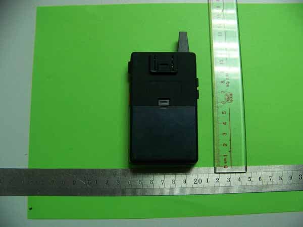
Click to zoom
Application Details
- Equipment Class
- CYY - Communications Receiver used w/Pt 15 Transmitter
- Date of Grant
- Apr 25, 2011
- Application Purpose
- Original Equipment
- Date of Application
- Apr 25, 2011
- Equipment Note
- WIRELESS GUIDE RECEIVER
- Frequency Range
- 915.02500000 - 916.97500000
- Country
- Malta
Documents & Files
Document Text
Text extracted from the exhibit documents filed with the FCC. Open a document above to read the original.
Users Manual
1 of 4 Pages Owner’s Manual Wireless Guide Transmitter/Receiver For Model WS823T/WS823R FEATURES ☞ 79 Channels ☞ LCD Backlighting ☞ Auto Squelch ☞ Emergency Channel ☞ SCAN Function ☞ Low Battery Indicator Use and Care 1. Do not use alcohol or cleaning solutions to clean the radio. 2. Do not immerse the radio in water. 3. Use a soft damp cloth to clean the radio 4. Dry the radio with dry lint-free cloth should it get wet. 5. Turn off the radio and remove the batteries during long-term storage. Introduction The WS823 represents the state-of-the-art in high-tech engineering. Designed for Transmitter and Receiver operation, this compact package is big in performance. It is a quality piece of electronic equipment, skillfully constructed with the finest components. The circuitry is all solid-state and mounted on a rugged printed circuit board. The WS823 is designed for reliable and trouble-free performance. Control Buttons & Indicators PTT for WS823T Channel Up/Down Power On/Off Earphone Jack for WS823R Microphone Jack for WS823T LCD EMG / SCAN Volume Up/Down for WS82 3R Charge Terminal 2 of 4 Pages LCD Display Operation Power On/Off : 1. Press the “ Power On/Off ” button for more than 1 second to turn the radio on. 2. Press the “ Power On/Off ” button for over 1 second to turn the radio off. Volume : 1. Press the “ Volume + “ button to increase the volume. 2. Press the “ Volume - “ button to decrease the volume during normal operation. Note : WS8 23R only Talking and Listening : To communicate, all radios in your group must be set at the same channel. 1. Press ”PTT “ button one time and speak in a normal voice into the microphone. The “TX” icon will appear continuously on the LCD Display when transmitting. 2. The RX icon will appear on the display when your radio is receiving a transmission. 3. To release the transmission, press “PTT” button one time again. Channel Selection : The WS823 has 79 channels available. To change channels: 1. Press the “Channel + or –“ button until the current channel segment flashes in radio on. 2. Press the “ PTT “button to save the new channel. Emergency : 1. Press the “ EMR ” button for more than 4 seconds to make Emergency channel. 2. Press the “ EMR ” button for over 4 seconds to release Emergency channel. SCAN : 1. Press the “ EMR ” button shortly to make channel scanning. 2. If found the TX signal, scanning will be stop. If you want to scanning again, press the “EMR” button shortly, then scanning will start again. Note : WS 823R only TX RX EMG Low Battery Emergency Channel Transmission Reception 3 of 4 Pages Factory Default setting for WS823 : At Power Off mode 1. Press and hold the “Channel +” button and press “Power On/Off ” button for WS 823T. 2. Press and hold the “Volume +” button and press “Power On/Off ” button for WS8 23R. Then will change to factory default setting (Channel 1). Technical Specification A. Specification Channels : 79 Channels Operating Frequency : UHF 915.0250 ~ 916.9750 MHz Power Source : Lithium Battery Output Power : Typically ERP 10mWatts B. Current Drain : WS803T : 100 mA max., Standby 10mA max. WS803R : 50 mA max., Standby 30/8mA max. C. Operating Time : Based on 3000mAH (Lithium battery) capacity WS803T : 27 hours, Standby 250 hours WS803R : 50 hours, Standby 137 hours Channel Frequency Chart [MHz] ** Channel 40 is the Emergency Channel 4 of 4 Pages CH No. Frequency CH No. Frequency CH No. Frequency 1 915.0250 28 915.7000 55 916.3750 2 915.0500 29 915.7250 56 916.4000 3 915.0750 30 915.7500 57 916.4250 4 915.1000 31 915.7750 58 916.4500 5 915.1250 32 915.8000 59 916.4750 6 915.1500 33 915.8250 60 916.5000 7 915.1750 34 915.8500 61 916.5250 8 915.2000 35 915.8750 62 916.5500 9 915.2250 36 915.9000 63 916.5750 10 915.2500 37 915.9250 64 916.6000 11 915.2750 38 915.9500 65 916.6250 12 915.3000 39 915.9750 66 916.6500 13 915.3250 40 916.0000 67 916.6750 14 915.3500 41 916.0250 68 916.7000 15 915.3750 42 916.0500 69 916.7250 16 915.4000 43 916.0750 70 916.7500 17 915.4250 44 916.1000 71 916.7750 18 915.4500 45 916.1250 72 916.8000 19 915.4750 46 916.1500 73 916.8250 20 915.5000 47 916.1750 74 916.8500 21 915.5250 48 916.2000 75 916.8750 22 915.5500 49 916.2250 76 916.9000 23 915.5750 50 916.2500 77 916.9250 24 915.6000 51 916.2750 78 916.9500 25 915.6250 52 916.3000 79 916.9750 26 915.6500 53 916.3250 27 915.6750 54 916.3500 FCC STATEMENT 1. This device complies with Part 15 of the FCC Rules. Operation is subject to the following two conditions: (1) This device may not cause harmful interference, and (2) This device must accept any interference received, including interference that may cause undesired operation. 2. Changes or modifications not expressly approved by the party responsible for compliance could void the user’s authority to operate the equipment. Transmitter FCC ID: ZF4WS823T Receiver FCC ID: ZF4WS823R NOTE: This equipment has been tested and found to comply with the limits for a Class B digital device, pursuant to Part 15 of the FCC Rules. These limits are designed to provide reasonable protection against harmful interference in a residential installation. This equipment generates, uses and can radiate radio frequency energy and, if not installed and used in accordance with the instructions, may cause harmful interference to radio communications. However, there is no guarantee that interference will not occur in a particular installation. If this equipment does cause harmful interference to radio or television reception, which can be determined by turning the equipment off and on, the user is encouraged to try to correct the interference by one or more of the following measures: -- Reorient or relocate the receiving antenna. -- Increase the separation between the equipment and receiver. -- Connect the equipment into an outlet on a circuit different from that to which the receiver is connected. -- Consult the dealer or an experienced radio/TV technician for help.
Block Diagram
LOW PASS OSC 21.25MHz CLOCK FILTER PLL IC VCO LNA SAW Filter MIXER ANT CPU BATT 4V B+ BATTERY DETECTOR 3V REGULATOR LB2LB1 VCC SWITCH MAIN_VCC VDD2 MCU VCC LB2LB1 SPK_ENABLE RX VCC SWITCH PLL SW RX VCC MAIN_VCC EN DATA CLOCK ENDATA OSC 4MHz 21.7M FILTER IF SYSTEM CF 450K AF AMP SP EXPANDING PLL SW RESET RXMUTE 24C02 EEPROM E_CLKE_DATA SPK_ENABLE RXMUTE SQ SQ SW LCD
External Photos
External Photo for model: WS823R
ID Label/Location Info
FCC Certification Label FCC ID: ZF4WS823R This device complies with Part 15 of the FCC Rules.Operation is subject to the following two conditions: 1. This device may not cause harmful interference, and 2. This device must accept any interference received,including interference that may cause undesired operation. Label Location on EUT EUT Bottom View/ FCC ID Label Location (The Label is placed on a fixed cover)
Internal Photos
Internal Photo for model: WS823T Antenna
Operational Description
The receiver consists of below parts: 1) 4.2V battery 2) Power supply control circuit: IC3, Q7, Q14, Q18 3) Microprocessor controller (MICRO-CONTROL UNIT): IC7 and Reset Circuit: C127, Q3, Q22, X1 (4MHz crystals) 4) Audio signal processing circuit: IC1, IC2, IC8 5) Voltage-controlled oscillatorVCOand Phase-locked loopPLL integrated circuit IC6 and Q27, X2 (21.25MHz crystals) 6) RF signal amplification circuit: Q6, Q8 7) Matched circuit: L1, L3, L7, C219, C217, C218 and receiving antenna. Power supply control circuit provides 3V stable voltage. VDD1 is 3V stable voltage output by IC3, Provided to the MCU and RF amplification. VDD2 provided to all other circuits except RF amplification and MCU. X1 is 4MHz crystals oscillator as clock source of MICRO-CONTROL UNIT. Audio signal processing circuit deal with the speech signal from the Microphone by amplified and compressed. X2 is 21.25MHz crystals as reference frequency of IC6. This device gets matched frequency by VCO and PLL. The device is battery-powered, speech signal are received by antenna, and reverted by matched network, then speed information input to the headset by amplified, extended processing.
Test Report
FCC PART 15 CLASS B EMI MEASUREMENT AND TEST REPORT For JUSTLISTEN TECHNOLOGY LIMITED 2, Independence Square, Valletta VLT 1520, Malta FCC ID:ZF4WS823R April 12, 2011 This Report Concerns: Original Report Equipment Type Wireless Guide Receiver Test Engineer: Jack Liu Report No.: BST11030416Y-1ER-3 Receive EUT Date/Test Date: April 1, 2011/ April 1, 2011-April 11, 2011 Reviewed By: Christina Prepared By: Shenzhen BST Technology Co.,Ltd. 3F,Weames Technology Building, No. 10 Kefa Road,Science Park, Nanshan District,Shenzhen,Guangdong,China Tel: 0755-267477513 Fax: 0755-267477513 ext.826 Note: The test report is specially limited to the above company and this particular sample only. It may not be duplicated without prior written consent of Shenzhen BST Technology Co.,Ltd. This report must not be used by the client to claim product certification,approval,or endorsement by NVLAP, NIST or any agency of the US Government. JUSTLISTEN TECHNOLOGY LIMITED FCC ID: ZF4WS823R BST FCC ID REPORT : BST11030416Y-1ER-3 Page 2/16 TABLE OF CONTENTS 1. GENERAL INFORMATION .................................................................................................... 3 1.1. Report information............................................................................................................ 3 1.2. Measurement Uncertainty................................................................................................. 3 2. PRODUCT DESCRIPTION ...................................................................................................... 4 2.1. EUT Description ............................................................................................................... 4 2.2. Block Diagram of EUT Configuration ............................................................................. 4 2.3. Support Equipment List .................................................................................................... 4 2.4. Test Conditions .................................................................................................................4 3. FCC ID LABEL........................................................................................................................... 5 4. TEST RESULTS SUMMARY ................................................................................................... 6 Modifications ................................................................................................................................ 6 5. TEST EQUIPMENT USED ....................................................................................................... 7 5.1. For Conducted Emission Test ........................................................................................... 7 5.2. For Radiated Emission Measurement ............................................................................... 7 6. CONDUCTED EMISSION TEST............................................................................................. 8 6.1. Block Diagram of Test Setup............................................................................................ 8 6.2. Test Standard .................................................................................................................... 8 6.3. Conducted Emission Limit(Class B) ................................................................................ 9 6.4. EUT Configuration on Test .............................................................................................. 9 6.5. Operating Condition of EUT ............................................................................................ 9 6.6. Test Procedure ..................................................................................................................9 6.7. Test Result ...................................................................................................................... 10 7. RADIATED EMISSION MEASUREMENT ......................................................................... 12 7.1. Block Diagram of EUT Configuration ........................................................................... 12 7.2. Test Standard ..................................................................................................................12 7.3. Radiated Emission Limit(Class B) ................................................................................. 13 7.4. EUT Configuration on Test ............................................................................................ 13 7.5. Operating Condition of EUT .......................................................................................... 13 7.6. Test Procedure ................................................................................................................ 13 7.7. Test Result ...................................................................................................................... 14 JUSTLISTEN TECHNOLOGY LIMITED FCC ID: ZF4WS823R BST FCC ID REPORT : BST11030416Y-1ER-3 Page 3/16 1. GENERAL INFORMATION 1.1. Report information 1.1.1.This report is not a certificate of quality; it only applies to the sample of the specific product/equipment given at the time of its testing. The results are not used to indicate or imply that they are application to the similar items. In addition, such results must not be used to indicate or imply that BST approves recommends or endorses the manufacture, supplier or use of such product/equipment, or that BST in any way guarantees the later performance of the product/equipment. 1.1.2.The sample/s mentioned in this report is/are supplied by Applicant, BST therefore assumes no responsibility for the accuracy of information on the brand name, model number, origin of manufacture or any information supplied. Additional copies of the report are available to the Applicant at an additional fee. No third part can obtain a copy of this report through BST, unless the applicant has authorized BST in writing to do so. Test…
Text truncated - open the document above for the full version.
Test Setup Photos
Radiated emissions test Conducted emissions test
Contact Information
Applicant
MASSIMILIANO BISCEGLIA(DIRECTOR)
Test Firm
emitel (Shenzhen) LimitedLouis Lin
Technical Specifications
| # | Rule Parts | Frequency Range | Power Output |
|---|---|---|---|
| 1 | 15B | 915.025 MHz - 916.975 MHz | - |
Other Applications from JUSTLISTEN TECHNOLOGY LIMITED
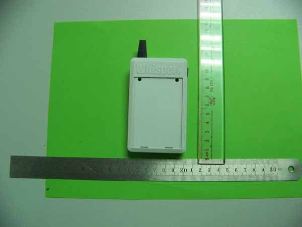
ZF4WS823T
Apr 25, 2011WIRELESS GUIDE TRANSMITTER
Equipment Class
DXX - Part 15 Low Power Communication Device Transmitter