ZFBC13FInduction Cooker
Foshan Shunde Ya-In Electric Appliance Manufacture CO.,LTD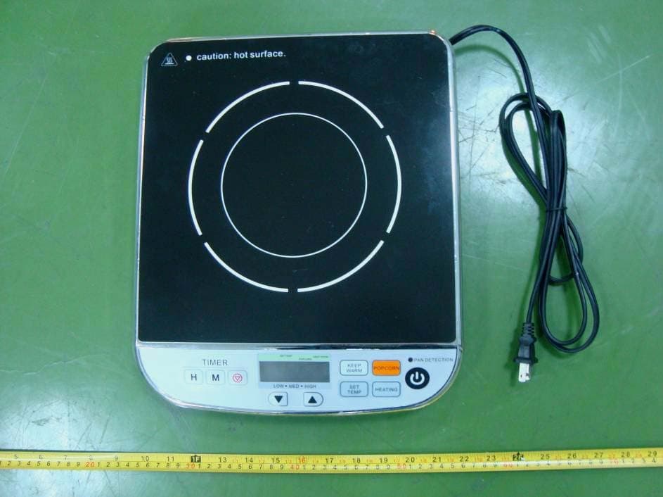
Click to zoom
Application Details
- Equipment Class
- 8CC - Part 18 Consumer Device
- Date of Grant
- May 04, 2011
- Application Purpose
- Original Equipment
- Date of Application
- May 04, 2011
- Equipment Note
- Induction Cooker
- Frequency Range
- 0.02000000 - 0.05500000
- Country
- China
Documents & Files
Document Text
Text extracted from the exhibit documents filed with the FCC. Open a document above to read the original.
Users Manual
Please this instuction. C13F ManualoflnductionCooker P o p c o r n HM T I MER L O W M ED HIG H D EE P FR Y PO P C OR N KEE P WARM K E E P WA R M P O P C O RN S ET T EMP HE A TI N G PAN D ETEC TI O N IMPORTANTSAFEGUARDS 1. Read all instructions before using the induction cooker. 2. Do not touch hot surfaces. Use handles or knobs. 3. To protect against electrical shock do not immerse cord, plugs in water or other liquid. 4. Close supervision is necessary when any appliance is used by or near children,so as to ensure that they do not play with the appliance. 5. Unplug from outlet when not in use and before cleaning. Allow to cool before putting on or taking off parts. 6. Do not operate any appliance with a damaged cord or plug or after the appliance malfunctions or has been damaged in any manner. Return appliance to the nearest authorized service facility for examination, repair, or adjustment. 7. The use of accessory attachments not recommended by the appliance manufacturer may cause injuries 8. Do not use outdoors.It is only for indoor use. 9. Do not let cord hang over edge of table or counter, or touch hot surfaces. 10. Do not place on or near a hot gas or electric burner, or in a heated oven. 11. Extreme caution must be used when moving an applian ce containing hot oil or other hot liquids. 12. Do not use appliance for other than intended use. 13. WARNING To prevent electric shock, unplug before cleaning. 16. Clean Cook-Top with Caution if a wet sponge or cloths used to wipe spills on a hot cooking area, be careful to avoid steam burn, some cleaners can produce noxious fumes if applied to a hot surface. 17. Any other servicing should be performed by an authorized services representative. 18. Metallic objects such as knives, forks, spoons and lids should not be placed on the plate to avoid this vessel to heat. 14. This appliance has polarized plug (one blade is wider than the other). To reduce the risk of electric shock, this plug is intended to fit into a polarized outlet only one way. If the plug does not fit fully into the outlet, reverse the plug. If it still does not fit, contact a qualified electrician, Do not attempt to modify the plug in any way. 15. Do Not cook on broken-Top If cook-top should break, cleaning solution and spillovers may penetrate the broken cook-top and create a risk electric shock. When using electrical appliances, basic safety precautions should always be followed including the following: 19. This appliance is not intended for use by persons (including children) with reduced physical,sensory or mental capabilities,or lack of experience and knowledge,unless , they have been given supervision or instruction concerning use of the appliance by a person responsible for their safety. 1 20.To disconnect,turn any control to “off”,then remove plug from wall outlet. Save thest instructions. Product Introduction Performance Applied voltage/frequency Rated power Dimension Weight (mm) (kg) C13F 120V~/60Hz Designations of parts Ceramic plate Airvent Air entry Supply cord 2 Induction cookers, with micro-computerized control and complete functions, are able to meet various kinds of cuisine demands by electromagnetic heating, really the optimal choice. Control panel Model 1300W 300x360x60 2.3 P o p c o r n H M TI ME R L O W ME D H I G H SE T T E MP PO PC OR N KE E P WAR M KEE P WA R M POP CO R N S ET TE MP H EAT I NG PAN D ETE C T I ON Parts name and assembly method ceramic plate plug air outlet air inlet control board set timer popcorn set temp heating on/off timer cancel control board display keep warm Operation Instructions 1. mode.if plug loosely,it will overheat to cause an accidenst,when the cooker works long. When use it,please plug into the socket tightly,after sound “b”, it turns to standby 3 Popcorn 2.,press Heating or Set Temp or Popcorn or Keep Warm , it’s ready to cook. Put the pan on the cooker Heating After press “Heating”the cooker is heating and displaying on the digital screen. press key to adjust power,with six levels. The lowest power The highest power Press “Popcorn” key to adjust weight of corn,with 2 options. When the digital screen shows put the corn and oil into the pan. When the digital screen shows it means popcorn is done. 1. adjust temperature.Temperature control range:300、320、340、360、380、400 After press “set temp”key,the digital screen show”400”,press to Set Temp The Lowest:300 The Highest:400 FF FF 4 SE T T E MP P OP COR N KE EP W A RM POP COR N K E EP W A RM PO PC O R N K EE P W A RM P OP CORN KE EP WAR M P OP CO RN KE EP WAR M POP CO RN KEE P W A RM POP CO RN KEE P W A RM P1 P1 P1 P1 P2 P1P2 P o p c o r n HM T IM E R LO W ME D H I G H PO P CO RN K EE P WA RM K EE P WAR M P O P C OR N SET TE M P HE ATIN G PA N D E T EC T I O N S E T T E MP SE T T E MP SE T T E MP S ET TEM P S ET TEM P S E T T EM P S E T T E MP Timer When the cooker is in Heating or Set Temp or mode,the function of timer to countdown can be started up. Heating When the cooker is in “Heating” mode,press key to set time, the Max is 9:59.when finishs countdown,it will turn off automatically. Time Minute Press key one time to add one more hour,the Max:9 hours. Press key one time to add one more minute,the Max:59 minutes. Time Minute 1. adjust temperature.Temperature control range:140、160、180 After press “Keep Warm”key,the digital screen show”140”,press to The Lowest:140 The Highest:180 Keep Warm FF FF Keep Warm Set Temp When the cooker is in “Set Temp” mode,press key to set time, the Max is 9:59.when finishs countdown,it will turn off automatically. Time Minute Press key one time to add one more hour,the Max:9 hours. Press key one time to add one more minute,the Max:59 minutes. Time Minute When the cooker is in “Keep Warm” mode,press key to set time, the Max is 9:59.when finishs countdown,it will turn off automatically. Time Minute Press key one time to add one more hour,the Max:9 hours. Press key one time to add one more minute,the Max:59 minutes. Time Minute Keep Warm 5 PO PCOR N K…
Text truncated - open the document above for the full version.
External Photos
EXHIBIT B - EUT EXTERNAL PHOTOGRAPHS EUT – Top View EUT – Bottom View
ID Label/Location Info
EXHIBIT A - FCC ID LABELING AND LOCATION FCC ID Label FCC ID Label Location The label shown shall be permanently affixed at a conspicuous location on the device and be readily visible to the user at the time purchase (Labeling requirements per 2.925) Label here
Internal Photos
EXHIBIT C - EUT INTERNAL PHOTOGRAPHS EUT – Cover off View EUT – Main Board Top View EUT – Main Board Bottom View EUT – Control Board Top View EUT – Control Board Bottom View EUT – Coil for Heating Top View EUT – Coil for Heating Bottom View
Schematics
11 22 33 44 55 66 77 88 D D C C B B A A AC FUSE 15A/250V C1 10uF 250VAC ZNR1471 D1 1N4007 D2 1N4007 R19 200K.F DB DB1≥ 15A/ ≥ 600V L1 C210uF R5390K.F0.5W R1610K.F C25102M C3 0.33uF/ ≥ 1000VDC CN3 CN4 R6 240K .F 0.5W R7 R15 3K.F L4 68uH CT1 EI19-295 D161N4148 D20 1N4148 R10 1K.F BZ1 R6215K.F R147.9K.F R50330.J R1815K.F C36 104M 1 2 3 X1 4.00MHz R60 4.7K.J 1 67 U2A LM339 2 45 U2B 3 1011 12 13 U2C LM339 R6127K.J R64 22K.J R135.5K .F R65 22K.J R47 100.J D12 1N4148 C10 222J R17 18K.F D14 1N4148 C24 221K C34 104M D13 1N4148 NTC2 P2.3P0.1/ADC1/INT1 NTC1 C33104M P0.4/ADC4 P0.3/ADC3 P0.2/ADC2VSSVDDXin/P1.0Xout/P1.1P0.0/ADC0INT0 R21 68K.F R22270K.F R48 330.J C13474K P0.6/ADC6/PWM P2.2 +18V +5V +5V +5V P2.4P2.5 P2.0/T0 P0.5/ADC5P0.7/ADC7 P2.1 P2.6/ADC8/CL0 GND +5V +5V GND GND GND GND GND GND GND GND GND GND GND GND GND GND 1412 18 1 15 16 17 7611 19 13 89203210 5 R521K.J GND C32104M +5V U3 R554.7K.J +18V D3 1N4007 R425.6.J R43100.J R56 6.8K.J +18V R576.8K.J D19 1N4148 +5V 123 CN5 C3-3 - + FAn DC18V +18V 123 12 CN6 12 1 CN2 1 CN1 1 N 1 L 5 6 C37 104M 89 14 U2DLM339 A +18V GND GND C11 474K C12474K GND +5V R71 27K .F GND R6330K.J Q3 A1015 Q4 C1815 Q7 C1815 Q10 8050 R49330.J R54 3.3K.J R69 100K.J D15 1N4148 C28103K R531K.J R74 51K.J ZNR2 471 R20 27K.F R70 510.J GND Q1 ≥ 25A/ ≥ 1200V C42104M + C4 33uF/250V C21 223M/1KV C30 104M R4 470K.J 0.5W R46330.J R67 51K R413.3.J D6 FR104 D11 1N4148 Q9C1815 ZD1 18V/0.5W GND GND D41N4007 GND Q2 13003 +18V R45 220.J R1 51.J 2W Q118050 +5V GND R3 100.J 1W + C91000uF 10V R51 1K.J R11 1K.F R12 1K.F U1 JC431 + C6 47uF/25V C22 56pK/500V A R4047J R39 3.6K.J C20 104K 14 8910 T1 JA-30B 100904F 250VAC +5V nRESET/P1.2 4 R8 R6~9 R23390K.F 0.5W C29 104M L2 C35104M GND R9 S3F9454B C80AB C13F +5V R12/220 +5V SW1 SW10 SW2 SW3 SW9 SW4 +5V R1 15K1% R2 1K1% R3 1K1% R4 1K1% R5 1K1% R6 2K1% R7 2K1% C1 104 SEG4 1 SEG3 2 SEG2 3 SEG1 4 SEG0 5 SEG5 28 SEG13 27 SEG14 26 SEG15 25 SEG16 24 SEG17 23 SEG18 22 SEG19 21 SEG26 20 SEG27 19 SEG28 18 SEG29 17 SEG30 16 COM0 12 COM1 13 COM2 14 COM3 15 CS 6 WR 7 DATA 8 VSS 9 VLCD 10 VDD 11 U1 D01A28 R11 5K1 LED3 +5V C2 104 COM4 1 COM3 2 COM2 3 COM1 4 P1 5 P2 6 P3 7 P4 8 P5 9 P6 10 P7 11 P8 12 P9 13 P10 14 LCD-GDE2018 LED2 R13/510 SW5R8 2K1% SW6 R15 1K1% 12345678 CN7 12345678 CN1 R25100K.F +5V R24330.J C27 104M Q6C1815 GND Q5 A1015 R9 2K1% SW7R10 2K1% SW8 LED1 R14/510 C26
Test Report
Note: This test report is prepared for the customer shown above and for the device described herein. It may not be duplicated or used in part without prior written consent from Bay Area Compliance Laboratories Corp. This report must not be used by the customer to claim product certification, approval, or endorsement by NVLAP*, or any agency of the Federal Government. * This report contains data that are not covered by the NVLAP accreditation and are marked with an asterisk “★” (Rev.2) FCC PART 18 MEASUREMENT AND TEST REPORT For Foshan Shunde Ya-In Electric Appliance Manufacture Co., Ltd. No. 8 LongxiaoRoad, Longyongkou, Ronggui Town, Shunde, Foshan, Guangdong China FCC ID: ZFBC13F Report Type: Original Report Product Type: Induction Cooker Test Engineer: Andy Xiong Report Number: RDG11012001 Report Date: 2011-01-28 Reviewed By: Lisa Zhu EMC Engineer Prepared By: Bay Area Compliance Laboratories Corp. (Shenzhen) 6/F, the 3rd Phase of WanLi Industrial Building, ShiHua Road, FuTian Free Trade Zone Shenzhen, Guangdong, China Tel: +86-755-33320018 Fax: +86-755-33320008 Foshan Shunde Ya-In Electric Appliance Manufacture Co., Ltd. FCC ID: ZFBC13F Report #: RDG11012001 Page 2 of 13 FCC Part 18 Test Report TABLE OF CONTENTS GENERAL INFORMATION.......................................................................................................................................3 PRODUCT DESCRIPTION FOR EQUIPMENT UNDER TEST (EUT) .....................................................................................3 OBJECTIVE...................................................................................................................................................................3 RELATED SUBMITTAL(S)/GRANT(S).............................................................................................................................3 TEST METHODOLOGY..................................................................................................................................................3 TEST FACILITY.............................................................................................................................................................3 SYSTEM TEST CONFIGURATION ..........................................................................................................................5 JUSTIFICATION.............................................................................................................................................................5 EUT EXERCISE SOFTWARE..........................................................................................................................................5 SPECIAL ACCESSORIES.................................................................................................................................................5 EQUIPMENT MODIFICATIONS.......................................................................................................................................5 EXTERNAL I/O CABLE..................................................................................................................................................5 CONFIGURATION OF TEST SETUP.................................................................................................................................5 BLOCK DIAGRAM OF TEST SETUP................................................................................................................................6 FCC §18.307 - CONDUCTED EMISSIONS ...............................................................................................................7 MEASUREMENT UNCERTAINTY....................................................................................................................................7 EUT SETUP..................................................................................................................................................................7 EMI TEST RECEIVER SETUP.........................................................................................................................................8 TEST EQUIPMENT LIST AND DETAILS...........................................................................................................................8 TEST PROCEDURE........................................................................................................................................................8 TEST RESULTS SUMMARY............................................................................................................................................8 TEST DATA..................................................................................................................................................................8 FCC §18.305 - FIELD STRENGTH ..........................................................................................................................11 MEASUREMENT UNCERTAINTY..................................................................................................................................11 EUT SETUP................................................................................................................................................................11 EMI TEST RECEIVER SETUP AND SPECTRUM ANALYZER SETUP................................................................................12 TEST EQUIPMENT LIST AND DETAILS.........................................................................................................................12 TEST PROCEDURE......................................................................................................................................................12 CORRECTED AMPLITUDE CALCULATION....................................................................................................................12 TEST DATA........................................................................................................................…
Text truncated - open the document above for the full version.
Test Setup Photos
EXHIBIT D - TEST SETUP PHOTOGRAPHS AC Line Conducted Emissions - Front View AC Line Conducted Emissions - Side View Field Strength - Front View Field Strength - Side View
Contact Information
Applicant
Foqiang Ouyang(manager)
Test Firm
Bay Area Compliance Laboratory Corp. (Shenzhen)John Chan
Technical Specifications
| # | Rule Parts | Frequency Range | Power Output |
|---|---|---|---|
| 1 | 18 | 0.02 MHz - 0.055 MHz | - |