ZFJ19620610161818Remote Controller for Select-your-color LED Light Strands
3H AND COMPANY LIMITED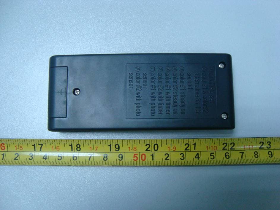
Click to zoom
Application Details
- Equipment Class
- DSC - Part 15 Security/Remote Control Transmitter
- Date of Grant
- Apr 27, 2011
- Application Purpose
- Original Equipment
- Date of Application
- Apr 27, 2011
- Equipment Note
- Remote Controller for Select-your-color LED Light Strands
- Frequency Range
- 433.92000000 - 433.92000000
- Company
- 3H AND COMPANY LIMITED
- Country
- Hong Kong
Documents & Files
Document Text
Text extracted from the exhibit documents filed with the FCC. Open a document above to read the original.
Users Manual
Made In ChinaBLH192109INST(V1) Instruction Manual Remote Controller for 2 in 1 LED Light Strands Included: •One Remote Controller for 2 in 1 LED Light Strands – One (23A 12V) battery included Product Instruction: 1. Front panel. 2. Indication lamp. 3. Feature key board. 4. Back panel. 5. Feature instructions. 6. Battery compartment cover. Installation Instructions: 1. Unpack remote controller. 2. Open the battery compartment cover at back side. Insert one “23A 12V” battery (included). Follow diagram in battery box for proper orientation. (Do not mix old and new batteries; do not mix alkaline, standard (carbon-zinc) or rechargeable (nickel-cadmium) batteries). 3. Close battery compartment cover. 4. Set controller button 1 to feature #1 on/off/Re-set to reset the light products for choosing or resetting a programbelow: (1) On/off/Re-set (2) Color #1 and Color #2 alternative – this will change the lights fromclear to multi every 1.5 seconds (approximately) Made In ChinaBLH192109INST(V1) (3) Color #1 Steady On – this will keep the lights in clear option on constant on (4) Color #2 Steady On – this will keep the lights in multi option on constant on (5) Color #1 with Timer – this will keep the lights in clear option for 6 hours and then switch off for 18 hours. It will come back every day at the same time as originally set and stay on for 6 hours each time. * For example: If you want the light strand to come on every day at 5pmyou need to turn the power switch to timer at 5pm. It will then come on every day at 5pmand stay lit until 11pm (6) Color #2 with Timer – this will keep the lights in multi option for 6 hours and then switch off for 18 hours. It will come back every day at the same time as originally set and stay on for 6 hours each time. * For example: If you want the light strand to come on every day at 5pmyou need to turn the power switch to timer at 5pm. It will then come on every day at 5pmand stay lit until 11pm (7)Color #1 with Photo Sensor – this will keep the lights in clear optionon when the surrounding area is dark. (8) Color #2 with Photo Sensor – this will keep the lights in multi optionon when the surrounding area is dark. Care Instructions: 1. If the indication lamp starts to go dim, replace battery of the same type (23A 12V). 2. After season, remove battery, and store in cool dry location Battery Disposal: 1. Do not dispose batteries in fire 2.Improper handling/disposal of batteries may cause batteries to explode or leak.Please dispose of batteries responsibly by throwing away batteries in a proper trash receptacle This remote controller can be used to control all our 2 in 1 LED Light Strands with built-in receiver. Indoor UseOnly Made In ChinaBLH192109INST(V1) Modifications Any changes or modifications made to this device that are not expressly approved by 3H Décor-Lite could void the user's authority to operate the equipment. This device complies with Part 15 of the FCC rules. Operation is subject to the following two conditions: 1. This device may not cause harmful interference, and 2. This device must accept any interference received, including interference that may cause undesired operation.
Cover Letter(s)
BLOCK A&B, 10F, MAI WAH INDUSTRIAL BUILDING, 1-7 WAH SING ST., KWAIHING, N.T., HONGKONG Tel: 852-27663377 Fax: 852-27745064
External Photos
EXHIBIT B - EUT EXTERNAL PHOTOGRAPHS EUT– Top View EUT– Bottom View EUT– Side View
ID Label/Location Info
EXHIBIT A - FCC ID LABELING AND LOCATION FCC ID Label FCC ID Label Location
Internal Photos
EXHIBIT C - EUT INTERNAL PHOTOGRAPHS EUT - Cover off View EUT - Main Board Top Components View Antenna EUT - Main Board Bottom Circuit View
Test Report
Note: This test report is prepared for the customer shown above and for the device described herein. It may not be duplicated or used in part without prior written consent from Bay Area Compliance Laboratories Corp. This report must not be used by the customer to claim product certification, approval, or endorsement by NVLAP*, or any agency of the Federal Government. * This report contains data that are not covered by the NVLAP accreditation and are marked with an asterisk “★” (Rev.2) FCC PART 15.231 MEASUREMENT AND TEST REPORT For 3H AND COMPANY LIMITED Block A&B, 10F, Mai Wah Industrial Building, 1-7 Wah Sing Street, Kwaihing, N.T., Hong Kong, China FCC ID: ZFJ19620610161818 Report Type: Original Report Product Type: Remote Controller Test Engineer: Alvin Huang Report Number: RSZ11031651 Report Date: 2011-04-28 Reviewed By: Merry Zhao EMC Engineer Prepared By: Bay Area Compliance Laboratories Corp. (Shenzhen) 6/F, the 3rd Phase of WanLi Industrial Building, ShiHua Road, FuTian Free Trade Zone Shenzhen, Guangdong, China Tel: +86-755-33320018 Fax: +86-755-33320008 3H AND COMPANY LIMITED FCC ID: ZFJ19620610161818 Report No.: RSZ11031651 Page 2 of 18 FCC Part15.231 Test Report TABLE OF CONTENTS GENERAL INFORMATION.......................................................................................................................................3 PRODUCT DESCRIPTION FOR EQUIPMENT UNDER TEST (EUT) ....................................................................................3 OBJECTIVE...................................................................................................................................................................3 RELATED SUBMITTAL(S)/GRANT(S).............................................................................................................................3 TEST METHODOLOGY..................................................................................................................................................3 TEST FACILITY.............................................................................................................................................................4 SYSTEM TEST CONFIGURATION ..........................................................................................................................5 JUSTIFICATION.............................................................................................................................................................5 SPECIAL ACCESSORIES.................................................................................................................................................5 EQUIPMENT MODIFICATIONS.......................................................................................................................................5 CONFIGURATION OF TEST SETUP.................................................................................................................................5 BLOCK DIAGRAM OF TEST SETUP................................................................................................................................5 SUMMARY OF TEST RESULTS ...............................................................................................................................6 FCC §15.203 - ANTENNA REQUIREMENT.............................................................................................................7 APPLICABLE STANDARD..............................................................................................................................................7 FCC §15.205, §15.209, §15.231 (B), - RADIATED EMISSIONS ..............................................................................8 MEASUREMENT UNCERTAINTY....................................................................................................................................8 EUT SETUP..................................................................................................................................................................8 EMI TEST RECEIVER SETUP.........................................................................................................................................9 TEST EQUIPMENT LIST AND DETAILS...........................................................................................................................9 TEST PROCEDURE........................................................................................................................................................9 APPLICABLE STANDARD............................................................................................................................................10 CORRECTED AMPLITUDE & MARGIN CALCULATION.................................................................................................10 TEST RESULTS SUMMARY..........................................................................................................................................10 TEST DATA................................................................................................................................................................10 FCC §15.231(C) – 20 DB BANDWIDTH TESTING ................................................................................................14 REQUIREMENT...........................................................................................................................................................14 TEST EQUIPMENT LIST AND DETAILS.........................................................................................................................14 TEST PROCEDURE......................................................................................................................................................14 TEST DATA................................................................................................................................................................14 FCC §15.231(A) -…
Text truncated - open the document above for the full version.
Test Setup Photos
EXHIBIT D - TEST SETUP PHOTOGRAPHS Radiated Emission – Front View (Below 1 GHz) Radiated Emission – Rear View (Below 1 GHz) Radiated Emission – Front View (Above 1 GHz) Radiated Emission – Rear View (Above 1 GHz)
Contact Information
Applicant
Gregory Wool(President)
Test Firm
Bay Area Compliance Laboratory Corp. (Shenzhen)John Chan
Technical Specifications
| # | Rule Parts | Frequency Range | Power Output |
|---|---|---|---|
| 1 | 15.231 | 433.92 MHz - 433.92 MHz | - |