ZGM-RV5090Wall Mount Radio
Magnadyne Corporation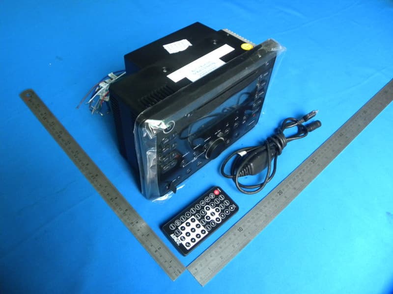
Click to zoom
Application Details
- Equipment Class
- DSS - Part 15 Spread Spectrum Transmitter
- Date of Grant
- Jul 10, 2013
- Application Purpose
- Original Equipment
- Date of Application
- Jul 09, 2013
- Equipment Note
- Wall Mount Radio
- Frequency Range
- 2402.00000000 - 2480.00000000
- Company
- Magnadyne Corporation
- Country
- United States
Documents & Files
Document Text
Text extracted from the exhibit documents filed with the FCC. Open a document above to read the original.
Users Manual
Operation and Installation Manual ® RV5090 AM / FM Stereo Multi-Media Receiver with Bluetooth MHz Please take the time to read all of the information in this manual. Familiarity with operation and instal- lation procedures will help you obtain the best possible performance from your new AM/FM Stereo Multi-Media Receiver. WARNING! To prevent fire or electrical shock hazard, do not expose this product to moisture, or remove cover or bottom screws. No user-serviceable parts inside. Refer servicing to qualified personnel. Introduction 2 Index Button Locations and Functions 3-4 Remote Control Button Locations and Functions 5 General Operation 6 Sound Controls 6-8 Speaker Selection 8 Setting the Clock 8-9 Sleep Timer Operation 9 Alarm Operation 10 Radio Operations 11-12 Disc Warnings 12 Music Disc Operation 13-15 MP3 Disc Operation 15-16 Movie Disc Operation 17-19 Setup Menu 19 IPOD Operations 20-22 USB Input 23 Bluetooth Operation 24 Audio/Video Input 25 Audio Input 25 Headphone Output 26 Reset Button 26 Additional Feature 26 Installation 27 Speaker Connections 28 Wiring and Auxiliary Connections 29-30 Safety Instructions 31 Warranty 32 Button Locations and Functions 3 1. Power On/Off: Press to turn the unit on or off. 2. Radio Station Recall Buttons (1-3): Press and release when recalling preset radio stations. Press and hold until the preset number appears to memorize a radio station. 3. Eject Button ( ): Press to eject the disc. 4. Disc Slot: To play a disc, insert the disc into slot with label facing up. 5. Display Area: This area displays all function information for the radio, clock, disc player and auxiliary input devices. 6. Radio Station Recall Buttons (4-6): Press and release when recalling preset radio stations. Press and hold until the preset number appears to memorize a radio station. 7. Display Dimmer Button (DIM): Press to select the desired level of brightness of the display. 8. Repeat Button: Disc Mode: Press to repeat a music disc track. Press again to cancel. IPOD Mode: (See IPOD Operations section for more details). 9. Music Disc Intro Button: Press to preview each track on the music disc for 15 seconds. Press again to cancel. 10. Music Disc Random Button: Press to play all the tracks on the music disc in random order. Press again to cancel. 11. Radio Scan Button: Press this button and the tuner will scan up, pausing for 5 seconds at each strong station. Press the button again to cancel the scan function. 12. Radio Seek Button: Press this button and the tuner will seek up to the next strong station and stop. 13. Infrared Eye: Receives the signals from the remote control. 14. Headphone Socket: Accepts 3.5mm stereo headphone jacks. MHz 1 4 7 9 10 13 1415 16 5 3 8 11 12 17 18 19 202122232425 28 29 30 31 32 26 2 6 27 4 Button Locations and Functions (Continued) 15. Play/Pause and Mute Button ( � ll): Radio and Multimedia Input Modes: Press to mute volume level. Press again to restore. Disc Mode: Press to pause disc play, press again to resume play. IPOD Mode: Press to pause play, press again to resume play. Bluetooth: Press to pause play, press again to resume play. 16. IPOD Selection Button: Press to choose IPOD input mode. 17. Seek Up ( �� l) Buttons: Radio Mode: Press to tune the radio to a higher frequency. Disc Mode: Press to search for the beginning of next track or chapter. IPOD Mode: Press to search for the beginning of the next track. Bluetooth Mode: Press to search for the beginning of the next track. 18. USB/Disc Selection Button: Press to choose between Disc and USB modes. 19. Seek Down (l �� ) Buttons: Radio Mode: Press to tune the radio to a lower frequency. Disc Mode: Press to search for the beginning or previous track or chapter. IPOD Mode: Press to search for the beginning of the previous track. Bluetooth Mode: Press to search for the beginning of the previous track. 20. Volume and Select Knob: Rotate to increase or decrease the volume level. Press to select the sound controls: Bass, Treble and Balance. 21. AM/FM Radio Selection Button: Press to choose Radio mode. Sequential presses will select radio bands: FM1, FM2, FM2 (MHz) and AM1, AM2 (KHz). 22. Auxiliary Input Selection Button (AUX): Press to choose auxiliary input modes: Audio/Video input front, Audio/Video input rear, Audio input rear or Bluetooth. 23. Audio/Video Input Jack: Press the AUX button until “AV IN F” appears in the display then plug in a device via the 3.5mm audio/video input plug. Note: The RV5090 does not control the device, it just allows the audio/video to be played through the system. 24. Reset Button: Press to reset the unit to it’s default settings. 25. USB Input: Press the USB/DISC button until “DISC” appears in the display. Then plug in your USB device. “USB” will then appear in the display. Note: The RV5090 will control the USB audio device. (See “USB Input” for more details). 26. Speaker Selection Buttons (A, B and C): Switches the speaker sets on and off. Refer to the LED indi- cators above the button to determine if the speaker set is on or off. 27. Bluetooth Indicator: Indicates Bluetooth status. (See “Bluetooth Operation” for more details). 28. Sleep Button (SLP): Sets the sleep timer. (See “Sleep Timer Operation” for more details). 29. Alarm Button (ALRM): Sets the alarm. (See “Alarm Operation” for more details). 30. Display Button (DISP): Press to display the clock or frequency in radio mode, track in music disc mode, chapter and elapse time in movie disc mode or track in IPOD mode. Press and hold to perform clock setting functions (See “Setting the Clock” for more details). 31. Radio AS/PS Button: Automatic radio station memory storing (AS) and Preset radio station scanning (PS). (See “AM/FM Operation” for more details). 32. Equalizer and Loudness Button (EQ/LOUD): Press to select between the preset sound equalization settings. Press and hold the button to boost high and low tones at low volume levels (loudness). 5 Remote Control Button Locations and Functions 1. Power On/…
Text truncated - open the document above for the full version.
Cover Letter(s)
MAGNADYNE CORPORATION FCC Confidentiality Request Number: CF303 Version: V01 Date: 01-02-2010 To the FCC and FCC TCB handling this application for certification Pursuant to 47 CFR Section 0.459(a) & (b), we, (the applicant / grantee) Company name MAGNADYNE CORPORATION Addresss 1111 W. Victoria Street City Compton Country United States request non-disclosure and confidential treatment for our certification under: Grantee Code Product Number FCC ID: ZGM -RV5090 of the following materials submitted within this certification application: (please cross what is applicable, or add other documents) Operational Description Block Diagrams Schematics Diagrams Above materials contain secrets, proprietary and technical information, which would customarily be guarded from competitors under 47 CFR, section 0.457(d)(2). Disclosure or publication or any portion of this company confidential material to other parties could cause substantial competitive harm and provide unjustified benefits for competitors. We understand that pursuant to 47 CFR section 0.457(d)(1)(ii) disclosure of the applicant and all accompanying documentation will not be made before the date of the grant. Attestation:
Cover Letter(s)
MAGNADYNE CORPORATION FCC Authorization Letter Number: CF304 Version: V01 Date: 01-02-2010 We, (the approval holder) Company name MAGNADYNE CORPORATION Addresss 1111 W. Victoria Street City Compton Country United States declare that the following representative (agent): Name (person) Sam Lv Company name DONGGUAN EMTEK CO., LTD. Addresss No.281, Guantai Road, Nancheng District, City Dongguan Country China is hereby authorized to apply the following equipment for certification on our behalf: Product Description Wall Mount Radio Type or Model(s) RV5090 Tradename or Brand(s) LINEAR SERIES We also authorize Teleconformity, Mr. M. Koop, (address: Rietven 31, 7534NH Enschede, Netherlands) to process this application. Attestation:
External Photos
General Appearance of the EUT
ID Label/Location Info
Label Location on EUT
Internal Photos
Antenna
RF Exposure Info
TRF No. FCC 15.247/A Page50of 55 Report No.: KAD130530100E 13. RF EXPOSURE EVALUATION According to FCC 1.1310: The criteria listed in the following table shall be used to evaluate the environment impact of human exposure to radio frequency(RF) Radiation as specified in §1.1307(b) Limits for Maximum Permissible Exposure(MPE) Frequency Range(MHz) Electric Field Strength(V/m) Magnetic Field Strength(A/m) Power Density(mW/cm 2 ) Average Time (A) Limits for Occupational/Control Exposures 300-1500 -- --F/3006 1500-100000 -- --5 6 (B) Limits for General Population/Uncontrol Exposures 300-1500 -- --F/1500 6 1500-100000 -- --1 30 13.1 Friis transmission formula: Pd=(Pout*G)\(4*pi*R 2 ) Where Pd= Power density in mW/cm 2 Pout=output power to antenna in Mw G= gain of antenna in linear scale Pi=3.1416 R= distance between observation point and center of the radiator in cm Pd the limit of MPE, 1mW/cm2. If we know the maximum gain of the antenna and total power input to the antenna, through the calculation, we will know the distance where the MPE limit is reached. 13.2 Measurement Result. Operating Mode Channel Frequency (MHz) Output Peak power (mW) Antenna Gain (dBi) Power density at 20cm (mW/ cm 2 ) Power density Limits (mW/cm 2 ) op-mode 1 2402 1.346 4 4.25E-04 1 op-mode 2 2441 1.422 4 4.49E-04 1 op-mode 3 2480 1.337 4 4.22E-04 1 op-mode 6 2402 0.902 4 2.85E-04 1 op-mode 7 2441 0.948 4 2.99E-04 1 op-mode 8 2480 0.869 4 2.74E-04 1 op-mode 10 2402 0.966 4 3.05E-04 1 op-mode 11 2441 0.998 4 3.15E-04 1 op-mode 12 2480 0.934 4 2.95E-04 1
Test Report
TRF No. FCC 15.247/A Page 1 of 55 Report No.: KAD130530100E ELECTROMAGNETIC EMISSIONS COMPLIANCE REPORT INTENTIONAL RADIATOR CERTIFICATION TO FCC PART 15 SUBPART C REQUIREMENT OF Wall Mount Radio MODEL No.: RV5090 BRAND NAME: LINEAR SERIES FCC ID: ZGM-RV5090 REPORT NO: KAD130530100E ISSUE DATE: July 04, 2013 Prepared for MAGNADYNE CORPORATION 1111 West Victory Street, Compton, CA. 90220, USA Prepared by DONGGUAN EMTEK CO., LTD. No.281, Guantai Road, Nancheng District, Dongguan, Guangdong, China TEL: 86-769-22807078 FAX: 86-769-22807079 TRF No. FCC 15.247/A Page 2 of 55 Report No.: KAD130530100E VERIFICATION OF COMPLIANCE Applicant: MAGNADYNE CORPORATION 1111 West Victory Street, Compton, CA. 90220, USA Manufacturer: MAGNADYNE CORPORATION 1111 West Victory Street, Compton, CA. 90220, USA Product Description: Wall Mount Radio Brand Name: LINEAR SERIES Model Number: RV5090 Serial Number: N/A Kind of Device: Bluetooth Ver. 2.1+EDR File Number: KAD130530100E Date of Test: May 30, 2013 to June 22, 2013 We hereby certify that: The above equipment was tested by DONGGUAN EMTEK CO., LTD. The test data, data evaluation, test procedures, and equipment configurations shown in this report were made in accordance with the procedures given in ANSI C63.4 (2009) and the energy emitted by the sample EUT tested as described in this report is in compliance with conducted and radiated emission limits of FCC Rules Part 15.247. The test results of this report relate only to the tested sample identified in this report. Approved By Sam Lv / Q.A. Manager DONGGUAN EMTEK CO., LTD. TRF No. FCC 15.247/A Page 3 of 55 Report No.: KAD130530100E Table of Contents 1. GENERAL INFORMATION ....................................................................................... 5 1.1 PRODUCT DESCRIPTION............................................................................................................... 5 1.2 RELATED SUBMITTAL(S) / GRANT (S)............................................................................................ 5 1.3 TEST METHODOLOGY.................................................................................................................. 5 1.4 SPECIAL ACCESSORIES................................................................................................................ 5 1.5 EQUIPMENT MODIFICATIONS........................................................................................................ 5 1.6 TEST FACILITY............................................................................................................................. 6 2. SYSTEM TEST CONFIGURATION ........................................................................... 7 2.1 EUT CONFIGURATION.................................................................................................................. 7 2.2 EUT EXERCISE............................................................................................................................ 7 2.3 TEST PROCEDURE....................................................................................................................... 7 2.4 LIMITATION.................................................................................................................................. 7 2.5 CONFIGURATION OF TESTED SYSTEM........................................................................................ 11 3. SUMMARY OF TEST RESULTS ............................................................................. 12 4. DESCRIPTION OF TEST MODES........................................................................... 12 5. RADIATED EMISSION TEST .................................................................................. 13 5.1 MEASUREMENT PROCEDURE..................................................................................................... 13 5.2 TEST SET-UP (BLOCK DIAGRAM OF CONFIGURATION)............................................................... 14 5.3 MEASUREMENT EQUIPMENT USED: ............................................................................................ 15 5.4 MEASUREMENT RESULT............................................................................................................. 15 5.5 RADIATED MEASUREMENT PHOTOS:........................................................................................... 21 6. CHANNEL SEPARATION TEST ............................................................................. 22 6.1 MEASUREMENT PROCEDURE..................................................................................................... 22 6.2 TEST SET-UP (BLOCK DIAGRAM OF CONFIGURATION)............................................................... 22 6.3 MEASUREMENT EQUIPMENT USED: ............................................................................................ 22 6.4 MEASUREMENT RESULTS:.......................................................................................................... 22 7. 20DB BANDWIDTH TEST ....................................................................................... 28 7.1 MEASUREMENT PROCEDURE..................................................................................................... 28 7.2 TEST SET-UP (BLOCK DIAGRAM OF CONFIGURATION)............................................................... 28 7.3 MEASUREMENT EQUIPMENT USED: ............................................................................................ 28 7.4 MEASUREMENT RESULTS:.......................................................................................................... 28 8. QUANTITY OF HOPPING CHANNEL TEST ........................................................... 34 8.1 MEASUREMENT PROCEDURE..................................................................................................... 34 8.2 TEST SET-UP (BLOCK DIAGRAM OF CONFIGURATION)............................................................... 34 8.3 MEASUREMENT EQUIPMENT USED: .................................…
Text truncated - open the document above for the full version.
Test Setup Photos
Setup Photos
Contact Information
Applicant
Ben Yeh
Technical Contact
Test Firm
EMTEK (DONGGUAN) CO.,LTDSam Lv
Technical Specifications
| # | Rule Parts | Frequency Range | Power Output |
|---|---|---|---|
| 1 | 15C | 2.40 GHz - 2.48 GHz | 1.40 mW |
Other Applications from Magnadyne Corporation
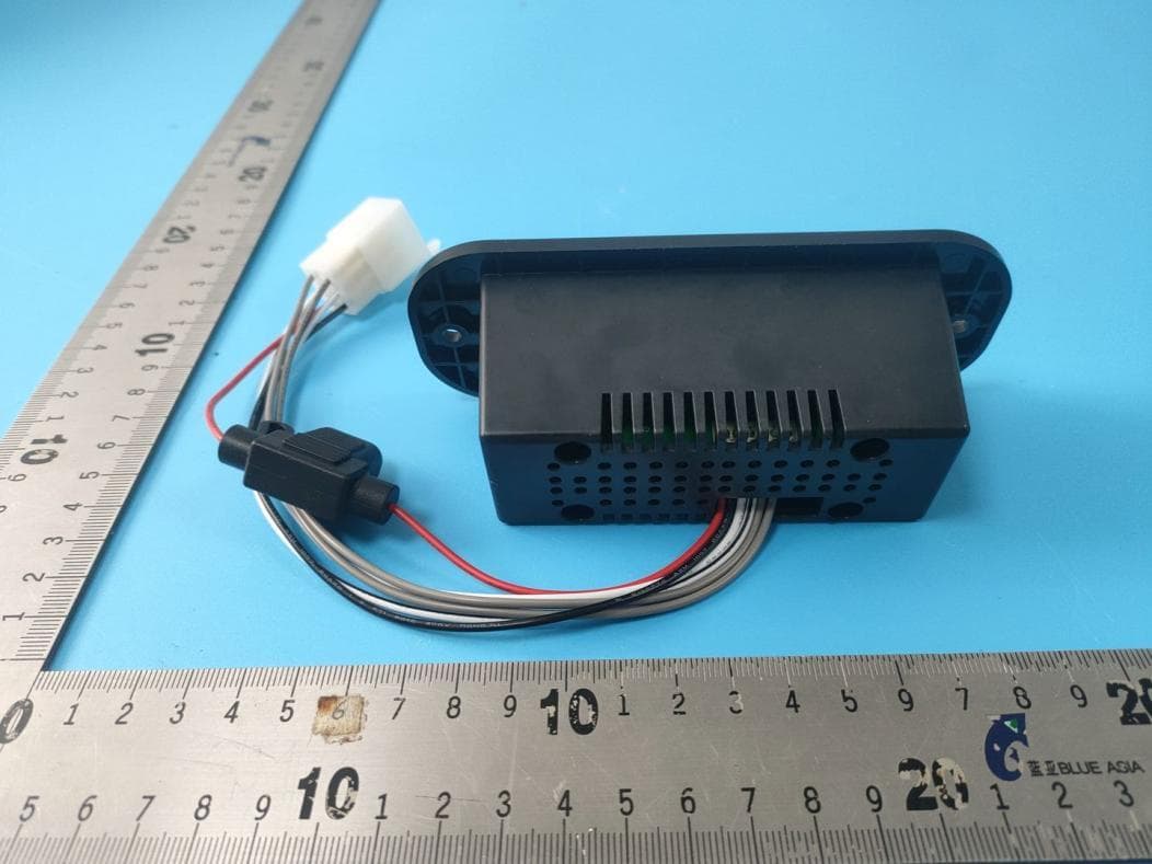
ZGM-LSBT1B-AMP
Apr 02, 2024BLUETOOTH RECEIVER AMPLIFIER
Equipment Class
DSS - Part 15 Spread Spectrum Transmitter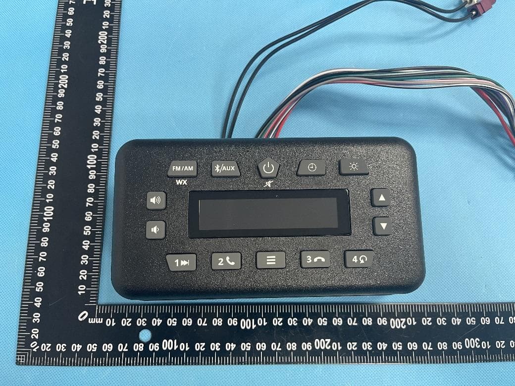
ZGM-AUC18239
Jul 17, 2023Mini Radio
Equipment Class
DSS - Part 15 Spread Spectrum Transmitter
ZGM-AT449150R
Mar 10, 2021Radio
Equipment Class
DSS - Part 15 Spread Spectrum Transmitter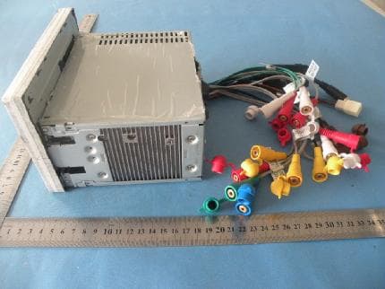
ZGM-M4-LCD
Apr 24, 2011CAR DVD PLAYER
Equipment Class
DXT - Part 15 Low Power Transceiver, Rx Verified