ZGN0929Warning Display for Counting Rifle Shots and Rounds
RADE Tecnologias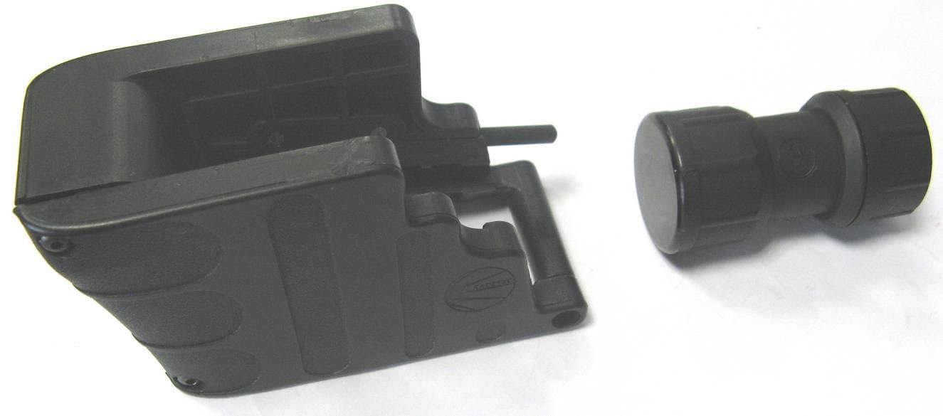
Click to zoom
Application Details
- Equipment Class
- DCD - Part 15 Low Power Transmitter Below 1705 kHz
- Date of Grant
- Jun 15, 2011
- Application Purpose
- Original Equipment
- Date of Application
- Jun 12, 2011
- Equipment Note
- Warning Display for Counting Rifle Shots and Rounds
- Frequency Range
- 0.12500000 - 0.12500000
- Company
- RADE Tecnologias
- Country
- Spain
Documents & Files
Document Text
Text extracted from the exhibit documents filed with the FCC. Open a document above to read the original.
Users Manual
F-MAN-1009 1 Fecha: Realizado: Revisado: M16 Warning LED Display User Manual Project P0058 Date: 15-April-2011 Produced by: Gonzalo García USER MANUAL Page 2 of 8 F-MAN-1009 TABLE OF CONTENTS 1 Safety instructions ..................................................................................... 3 2 Components of the “M16 Warning LED Display”........................................ 3 3 Technical specifications ............................................................................. 6 4 Installation ................................................................................................. 7 5 Operation................................................................................................... 7 6 Maintenance .............................................................................................. 8 USER MANUAL Page 3 of 8 F-MAN-1009 1 Safety instructions Observe the following basic safety rules for firearms before installing the device: - Handle the weapon as if it were always loaded. - Never aim at objects that are not intended targets. - Keep your finger off the trigger until the target is in view and you are ready to fire. - Be sure of the target and be sure that it is in front of you. The “M16 Warning LED Display” is an accessory to be installed on the M16 rifle, and as such it must be handled with care. The tool required for installation is a 2-mm Allen wrench (5/64”). 2 Components of the “M16 Warning LED Display”. Special follower with magnets: This follower is required for the system to work. It is completely compatible with the original follower, and it includes embedded magnets. To cover the greatest possible number of magazines used in the M16, two special followers with magnets have been designed: one to be installed on the 30-round aluminum magazine manufactured by C-Products and another to be installed on the 30-round plastic magazine manufactured by Lancer. Details of the follower manufactured by C-Products. USER MANUAL Page 4 of 8 F-MAN-1009 Details of the follower manufactured by Lancer Accessory installed around the weapon’s magazine port This element consists of two parts of injected polyamide fiber, which are joined by screws. It incorporates the push button. The Electronic Control Unit is also integrated in this component, which controls the operation of the device. The central spacer sheet is not installed on all weapons. Depending on the weapon’s manufacturer, the port has a different size, and the sheet is used to ensure that this accessory is fastened securely to the weapon’s magazine port. A 2-mm (5/64”) Allen wrench is used. USER MANUAL Page 5 of 8 F-MAN-1009 LED Display Accessory This element is installed on a Picatinny rail located on the weapon’s hand guard. The accessory is fastened using a commercial cylindrical clamp for a diameter of 1” (25.4 mm). The clamp has a width of less than 0.71” (18 mm) and is fastened to the Picatinny rail. This accessory has a small mark, which must be situated at the top so that the display is positioned correctly and can be read correctly. Width < 0.71” (18 mm) Mark indicating the top USER MANUAL Page 6 of 8 F-MAN-1009 3 Technical specifications Operating temperature range: -20º C to 60º C. Power supply: 3V6, 1000 mAh lithium battery welded to the Electronic Control Unit; 3V, 750 mAh, replaceable lithium battery on the LED display accessory. Battery life: Over 10 years for the battery installed on the Electronic Control Unit. Over 25,000 display operations with the two digits illuminated. FCC Certification : This device complies with Part 15 of the FCC Rules. Operation is subject to the following two conditions: 1. This device may not cause harmful interference. 2. This device must accept any interference received, including interference that may cause undesired operation. Protection against rain, dust, and sand: meets IP67 specifications. Dimensions of the accessory on the weapon’s magazine port: 100 x 70 x 50 mm (L x W x H) Dimensions of the LED display accessory: Diameter x height: 40 mm x 65 mm Approximate dimensions of the two followers: 70 x 45 x 25 mm (L x W x H) Weight of the accessory for the weapon’s magazine port: 122 g. Weight of the LED display accessory: 55 g. Weight of the two RADE followers: 21 g. USER MANUAL Page 7 of 8 F-MAN-1009 4 Installation Take the weapon and proceed to install the accessory on the magazine port. For this operation, only a 2-mm Allen wrench is required for tightening the three fastening bolts. Subsequently, a Picatinny rail and a round fastening clamp are required for installing the LED display accessory. The complete device mounted on an M16 rifle is shown below. The yellow button visible on the side is pressed by the user to access the operating functions. After performing the preceding operations and in order for the “LED Warning Display” to work correctly, a magazine that has a follower with embedded magnets must be inserted in the weapon. Extreme care must be taken when disassembling and assembling the magazine so that no parts are damaged and so that assembly is correct. 5 Operation Once the device is installed on the weapon, the user is provided with diverse information through the LED and Display. This information can be classified as follows: a) Query operating mode by pressing the button with a quick press: the display shows the number of rounds in the magazine, from 0 to 12. If there are more than 12 rounds in the magazine, no information is shown on the display. USER MANUAL Page 8 of 8 F-MAN-1009 b) Operating mode by firing: if the device is operational, there are two cases: - If there are more than three rounds in the magazine, the display shows the number of rounds in the magazine, up to a maximum of twelve. - If there are three rounds or fewer in the magazine, the red LED immediately illuminates according to the sequence in the following table: Rapidly flashing red 0 Rounds in the magazine Slow flashing red 1 Round in the magazine Steady red 2 or…
Text truncated - open the document above for the full version.
External Photos
DW M16 Photographs Page 1 of 1 Confidential document • EXTERNAL PRODUCT PHOTOGRAPHS
ID Label/Location Info
DW M16 – Label information Page 1 of 1 Confidential document Label information engraved with laser 0947/000271 Made in Spain FCC ID:ZGN0929
Test Report
TEST REPORT FROM RFI GLOBAL SERVICES LTD Test of: DW M16 FCC ID: ZGN0929 To: FCC Part 15.209; Part 15.215(c): 2010 Subpart C Test Report Serial No: RFI-RPT-RP78710JD03A This Test Report Is Issued Under The Authority Of Chris Guy, Head of Global Approvals: Checked By: Ian Watch Signature: Date of Issue: 31 May 2011 This report is issued in Adobe Acrobat portable document format (PDF). It is only a valid copy of the report if it is being viewed in PDF format with the following security options not allowed: Changing the document, Selecting text and graphics, Adding or changing notes and form fields. This report may not be reproduced other than in full, except with the prior written approval of RFI Global Services Ltd. The results in this report apply only to the sample(s) tested. TEST REPORT SERIAL NO: RFI-RPT-RP78710JD03A VERSION NO. 1.0 ISSUE DATE: 31 MAY 2011 Page 2 of 15 RFI Global Services Ltd This page has been left intentionally blank. TEST REPORT SERIAL NO: RFI-RPT-RP78710JD03A VERSION NO. 1.0 ISSUE DATE: 31 MAY 2011 RFI Global Services Ltd Page 3 of 15 Table of Contents 1. Customer Information .................................................................................................................. 4 2. Summary of Testing ..................................................................................................................... 5 2.1. General Information 5 2.2. Summary of Test Results 5 2.3. Methods and Procedures 5 2.4. Deviations from the Test Specification 5 3. Equipment Under Test (EUT) ....................................................................................................... 6 3.1. Identification of Equipment Under Test (EUT) 6 3.2. Description of EUT 6 3.3. Modifications Incorporated in the EUT 6 3.4. Additional Information Related to Testing 7 3.5. Support Equipment 7 4. Operation and Monitoring of the EUT during Testing ............................................................... 8 4.1. Operating Modes 8 4.2. Configuration and Peripherals 8 5. Measurements, Examinations and Derived Results .................................................................. 9 5.1. General Comments 9 5.2. Test Results 10 5.2.1. Transmitter Fundamental Field Strength 10 5.2.2. Transmitter Radiated Spurious Emissions 11 5.2.3. Transmitter 20 dB Bandwidth 13 6. Measurement Uncertainty .......................................................................................................... 14 Appendix 1. Test Equipment Used ................................................................................................ 15 TEST REPORT SERIAL NO: RFI-RPT-RP78710JD03A VERSION NO. 1.0 ISSUE DATE: 31 MAY 2011 Page 4 of 15 RFI Global Services Ltd 1. Customer Information Company Name: Rade Tecnologias S.L. Address: Av. Diagonal Plaza 14 Nave 61 50197 Zaragoza Spain TEST REPORT SERIAL NO: RFI-RPT-RP78710JD03A VERSION NO. 1.0 ISSUE DATE: 31 MAY 2011 RFI Global Services Ltd Page 5 of 15 2. Summary of Testing 2.1. General Information Specification Reference: 47CFR15.207 and 47CFR15.209 Specification Title: Code of Federal Regulations Volume 47 (Telecommunications) 2010: Part 15 Subpart C (Intentional Radiators) - Sections 15.207 and 15.209 Site Registration: FCC: 209735; Location of Testing: RFI Global Services Ltd, Wade Road, Basingstoke, Hampshire, RG24 8AH. Test Dates: 6 May 2011 to 26 May 2011 2.2. Summary of Test Results FCC Reference (47CFR) Measurement Result Part 15.209 Transmitter Fundamental Field Strength Part 15.209 Transmitter Radiated Emissions Part 15.215(c) Transmitter 20 dB Bandwidth Key to Results = Complied = Did not comply 2.3. Methods and Procedures Reference: ANSI C63.10 (2009) Title: American National Standard for Methods of Measurement of Radio-Noise Emissions from Low-Voltage Electrical and Electronic Equipment in the Range of 9 kHz to 40 GHz 2.4. Deviations from the Test Specification For the measurements contained within this test report, there were no deviations from, additions to, or exclusions from the test specification identified above. TEST REPORT SERIAL NO: RFI-RPT-RP78710JD03A VERSION NO. 1.0 ISSUE DATE: 31 MAY 2011 Page 6 of 15 RFI Global Services Ltd 3. Equipment Under Test (EUT) 3.1. Identification of Equipment Under Test (EUT) Brand Name: RADETEC Model Name or Number: DW M16 Serial Number: P0058 Hardware Version Number: Version 1 Software Version Number: Version 1 FCC ID: ZGN0929 3.2. Description of EUT The equipment under test was a bullet-counter. It comprised a transmitter designed to be mounted around the magazine, and a separate receiver which was fitted with an LED display to show the bullet count. 3.3. Modifications Incorporated in the EUT No modifications were applied to the EUT during testing. TEST REPORT SERIAL NO: RFI-RPT-RP78710JD03A VERSION NO. 1.0 ISSUE DATE: 31 MAY 2011 RFI Global Services Ltd Page 7 of 15 3.4. Additional Information Related to Testing Tested Technology: Low power transmitter Power Supply Requirement: Nominal 3.6 V DC Type of Unit: Transmitter Transmit Frequency Range: 125 kHz 3.5. Support Equipment The following support equipment was used to exercise the EUT during testing: Description: Trigger relay box. Brand Name: RADETEC Model Name or Number: Not marked or stated Serial Number: Not marked or stated TEST REPORT SERIAL NO: RFI-RPT-RP78710JD03A VERSION NO. 1.0 ISSUE DATE: 31 MAY 2011 Page 8 of 15 RFI Global Services Ltd 4. Operation and Monitoring of the EUT during Testing 4.1. Operating Modes The EUT was tested in the following operating mode(s): • Maximum duty cycle was produced by adjusting the rate of EUT triggering on the support relay box to its maximum level. 4.2. Configuration and Peripherals The EUT was tested in the following configuration(s): • The EUT was powered by supplying 3.6V DC to the red and black cables via an external power supply. • The EUT was triggered by providing a signal from the support relay box via the green and white cables. TEST REPORT SERIAL NO: RFI-RPT-RP78710JD03A VER…
Text truncated - open the document above for the full version.
Contact Information
Applicant
Raquel Felipe
Technical Contact
Non-Technical Contact
APPLUS+LGAILluis Boada
[email protected]34 935 672 000
Test Firm
UL VS LtdDarren Rust
Technical Specifications
| # | Rule Parts | Frequency Range | Power Output |
|---|---|---|---|
| 1 | 15C | 0.125 MHz - 0.125 MHz | - |