ZGPGPWM-900RWireless Receiver
GPI KOREA, Inc
Click to zoom
Application Details
- Equipment Class
- DSS - Part 15 Spread Spectrum Transmitter
- Date of Grant
- Dec 07, 2014
- Application Purpose
- Original Equipment
- Date of Application
- Dec 07, 2014
- Equipment Note
- Wireless Receiver
- Frequency Range
- 902.50000000 - 927.00000000
- Company
- GPI KOREA, Inc
- Country
- South Korea
Documents & Files
Document Text
Text extracted from the exhibit documents filed with the FCC. Open a document above to read the original.
Users Manual
900MHzDigital Wireless Microphone System USER GUIDE TABLE OF CONTENTS 1. Description of the units ....................................... ........................3 1. Quick Set Up and Operation .......................................................4 2. Installation....................................................................................5 3. Guidelines For Best Performance................................................6 4. Troubleshooting Guide.................................................................7 5. Technical Specifications...............................................................8 6. Factory Service ............................................................................9 7. Warranty................................ ......................................................9 8. Accessories and Parts ............................... ...................................9 FCC NOTICE THIS DEVICE COMPLIES WITH PART 15 OF THE FCC RULES. OPERATION IS SUBJECT TO THE FOLLOWING TWO CONDITIONS: (1) THIS DEVICE MAY NOT CAUSE HARMFUL INTERFERENCE, AND (2) THIS DEVICE MUST ACCEPT ANY INTERFERENCE RECEIVED, INCLUDING INTERFERENCE THAT MAY CAUSE UNDERSIRED OPERATION. < Part 15.106> This equipment has been tested and found to comply with the limits for a Class B digital device, pursuant to part 15 of the FCC Rules. These limits are designed to provide reasonable protection against harmful interference in a residential installation. This equipment generates, uses and can radiate radio frequency energy and, if not installed and used in accordance with the instructions, may cause harmful interference to radio communication. However, there is no guarantee that interference will not occur in a particular installation. If this equipment does cause harmful interference to radio or television reception, which can be determined by turning the equipment off and on, the user is encouraged to try to correct the interference by one or more of the following measures : - Reorient or relocate the receiving antenna. - Increase the separation between the equipment and receiver. - Connect the equipment into an outlet on a oircuit difference from that to which the receiver is connected. - Consult the dealer of an experienced radio/TV technician for help. NOTE : The manufacturer is not responsible for any radio or TV interference caused by unauthorized modifications to this equipment. Such modifications could void the user's authority to operate the equipment. NOTE : The wireless receiver complies with the FCC RF radiation exposure limits set forth for an uncontrolled environment. This equipment should be installed and operated with a minimum distance of 20cm between the radiator and any part of your body. DESCRIPTION Base (Receiver) Transmitter Green LED: In-use, Record RED LED: Charging Green LED: Full charge Terminal For charging Antenna Connection Modular Jack Audio Jack Input Record Button Lapel Mic. Cover Emergency Button Green: In-use (Light On) Record (Flashing) RED LED: Out of Range RED LED: Low Battery Audible and Vibration Selectable Switch Power On/Off Switch 1. QUICK SET UP AND OPERATION Synching Up the Transmitter and Base The synch operation only needs to be performed the first time a system is used, or a new bodypack is used with a base previously synched to another bodypack. Do not perform the synch operation multiple times; it only needs to be done one time when a new bodypack is used with a new base. 1) Turn the transmitter power switch to ON and place the transmitter in the recharge cradle of the base. The transmitter goes in the base with the belt clip facing out. 2) The recharge LED will light (Green if fully charged, Red if charging). Leave the transmitter in the cradle for 4 hours for a full charge. 3) Press the REC button on the transmitter and hold until the In-Use LED on the transmitter and base start to flash, then release the button. 4) After a few seconds the light will stop flashing, and a beep will sound (If the beep is enabled). 5) The transmitter and base are now synched and will continue to be until another transmitter is linked to that base. Normal Operation 1) With the transmitter synched up, remove it from the cradle, plug in the lapel microphone (if used) and place the transmitter on your belt. 2) When you remove Transmitter from the cradle, The TR and Base’s In-USE LED will light a constant Green and you will hear short beep. To start the recording, press the REC button and the In-Use LED will blink in green. 3) To end recording, press the REC button and the In-Use LED will light a constant green. 4) At the end of your shift turn the transmitter off and replace it in the charging cradle. Out of Range 1) The transmitter will alert you with Audible warning beeps (two tone) and the In-Use LED will blink in red. 2) Move closer to the receiver base and the link will be re-established once you return to normal range. The In-Use LED will light constant green when link is back to normal operation. 3) If the link is not re-established within 30 seconds, the transmitter and receiver will return to standby mode. 4) If you went out of range in Standby mode, or the unit reverted to standby mode, re-enter normal range and press the In-Use button. Operation will return to normal. 5) If you will be out of range for a long period of time, turn the bodypack off. Low Battery Warning 1) If the transmitter Low BATT indicator (red) starts flashing or you hear warning beeps, return the transmitter to its cradle on the receiver to fully charge the transmitter. 2) The Charge LED indicator will light constant green when the unit is fully charged. EMG Panic Button (if wired for use in your vehicle) 1) The EMG or Panic Button can be programmed to do many things but may not be connected in your vehicle. Check with your technical department to understand what this button will control before you use it. 2) In Record mode: Press the EMG button on the transmitter, a beep will sound and the …
Text truncated - open the document above for the full version.
Cover Letter(s)
GPI KOREA, Inc Daebang Triplaon B-dong 201, 158 Haneulmaeul-ro, Ilsandong-gu, Goyang-si, Gyeonggi-do, KOREA Date: December 01, 2014 Federal Communications Commission 7435 Oakland Mills Road Columbia MD 21046 To whom it may concern: I, the undersigned, hereby authorize KT Kang of KES Co., Ltd. and hereafter referred to as KES Co., Ltd., to act on our behalf in all manners relating to application for equipment authorization, including signing of all documents relating to these matters. Any and all acts carried out by KT Kang of KES Co., Ltd. on our behalf shall have the same effect as acts of our own. I, the undersigned, hereby certify that we are not subject to a denial of federal benefits, that includes FCC benefits, pursuant to Section 5301 of the Anti-Drug Abuse Act of 1988, 21 U.S.C. 853(a). In authorizing KES Co., Ltd. as our agent, we still recognize that we are responsible to: a) comply with the relevant provisions of the certification program; b) make all necessary arrangements for the conduct of the evaluation, including provision for examining documentation and access to all areas, records (including internal audit reports) and personnel for the purposes of evaluation (e.g. testing, inspection, assessment, surveillance, reassessment) and resolution of complaints; c) make claims regarding certification only in respect of the scope for which certification has been granted; d) do not use our product certification in such a manner as to bring the Certification Division into disrepute and not make any statement regarding our product certification which the Certification Division may consider misleading or unauthorized; e) upon suspension or cancellation of certification, discontinue use of all advertising matter that contains any reference thereto and return any certification documents as required by the Certification Division; f) use certification only to indicate the products are certified as being in conformity with specified standards; g) endeavor to ensure that no certificate or report nor any part thereof is used in a misleading manner; GPI KOREA, Inc Daebang Triplaon B-dong 201, 158 Haneulmaeul-ro, Ilsandong-gu, Goyang-si, Gyeonggi-do, KOREA h) ensure that any reference to our product certification in communication media such as documents, brochures or advertising, complies with the requirements of the Certification Division; i) keep a record of all complaints made known to the us relating to the product’s compliance with requirements of the relevant standard and to make these records available to the Certification Division when requested; j) take appropriate action with respect to such complaints and any deficiencies found in products or services that affect compliance with the requirements for certification; k) document the actions taken. This authorization is valid until further written notice from the applicant. Sincerely Yours, Kijin Jang/ Manager GPI KOREA, Inc REMARK: 1. This authorization letter will be sent along with your application when filing with the Certification Division. 2. Please follow the format and type it on company letterhead and send original to us. 3. Authorized signature must be in agreement with grantee code contact in FCC database.
Cover Letter(s)
GPI KOREA, Inc Daebang Triplaon B-dong 201, 158 Haneulmaeul-ro, Ilsandong-gu, Goyang-si, Gyeonggi-do, KOREA Date: December 01, 2014 Federal Communications Commission Authorization and Evaluation Division Confidentiality Request regarding application for certification of FCC ID: ZGPGPWM-900R Pursuant to Sections 0.457 and 0.459 of the Commission’s Rules, we hereby request confidential treatment of information accompanying this application as outlined below: Exhibit Type File Name Part List CONF APPENDIX_GPWM-900R_Part List.PDF Schematics Diagram(s) CONF APPENDIX_ GPWM-900R_Schemetics.PDF Block diagram CONF APPENDIX_ GPWM-900R_Block diagram.PDF Operation description CONF APPENDIX_ GPWM-900R_Operation description.PDF The above materials contain trade secrets and proprietary information not customarily released to the public. The public disclosure of these materials may be harmful to the applicant and provide unjustified benefits to its competitors. The applicant understands that pursuant to Section 0.457 of the Rules, disclosure of this application and all accompanying documentation will not be made before the date of the Grant for this application. Sincerely, Kijin Jang /Manager GPI KOREA, Inc
External Photos
External photos Model: GPWM-900R Page 1 of 5 External photos Model: GPWM-900R Page 2 of 5 External photos Model: GPWM-900R Page 3 of 5 External photos Model: GPWM-900R Page 4 of 5 External photos Model: GPWM-900R Page 5 of 5 N/A
ID Label/Location Info
Label and Location Model No.: GPWM-500R Page 1 of 1 GPI KOREA, Inc Model: GPWM-900R FCC ID: ZGPGPWM-900R This device complies with Part 15 of the FCC Rules. Operation is subject to the following two conditions: (1) This device may not cause harmful interference, and (2) this device must accept any interference received, including interference that may cause undesired operation. Made In Korea
Internal Photos
Internal photos Model No.: GPWM-900R Page 1 of 4 Internal photos Model No.: GPWM-900R Page 2 of 4 Internal photos Model No.: GPWM-900R Page 3 of 4 Internal photos Model No.: GPWM-900R Page 4 of 4 N/A
RF Exposure Info
RF exposure According to FCC part 1.1310 : The criteria listed in the following table shall be used to evaluate the environment impact of human exposure to radio frequency (RF) radiation as specified in § 1.1307(b) Limits for Maximum Permissible Exposure (MPE) f= frequency in ㎒ Friis transmission formula: Pd = (Pout×G)/(4×pi×R 2 ) Where, Pd = power density in ㎽/㎠ Pout = output power to antenna in ㎽ G = gain of antenna in linear scale Pi = 3.1416 R = distance between observation point and center of the radiator in cm Pd the limit of MPE, f/1500 ㎽/㎠. If we know the maximum gain of the antenna and the total power input to the antenna, through the calculation, we will know the distance where the MPE limit is reached. Results Channel Frequency (㎒) Peak output power (㏈m) Antenna gain (㏈i) Power density at 20 ㎝(㎽/㎠) Limit (㎽/㎠) Low 902.5 13.69 1.8 0.003 13 0.60 Middle 915.0 13.58 1.8 0.003 05 0.61 High 927.0 12.80 1.8 0.002 55 0.62 Frequency range (㎒) Electric field strength(V/m) Magnetic field strength (A/m) Power density (㎽/㎠) Average time (A) Limits for Occupational / Control Exposures 300 – 1 500 -- -- f/300 6 1 500 - 100000 -- -- 5 6 (B) Limits for General Population / Uncontrol Exposures 300 – 1 500 -- -- f/1500 6 1 500 – 100 000 -- -- 1 30
Test Report
KES Co., Ltd. C-3701, Simin-daero 365-40l, Dongan-gu, Anyang-si, Gyeonggi-do, 431-716, Korea Tel: +82-31-425-6200 / Fax: +82-31-424-0450 www.kes.co.kr Test report No.: KES-RF-14T0055 Page (2 ) of (33) This report shall not be reproduced except in full, without the written approval of KES Co., Ltd. The test results in the report only apply to the tested sample. KES-P-5101-14 Rev. 1 KES A4 Revision history Revision Date of issue Test report No. Description - 2014.12.04 KES-RF-14T0055Initial KES Co., Ltd. C-3701, Simin-daero 365-40l, Dongan-gu, Anyang-si, Gyeonggi-do, 431-716, Korea Tel: +82-31-425-6200 / Fax: +82-31-424-0450 www.kes.co.kr Test report No.: KES-RF-14T0055 Page (3 ) of (33) This report shall not be reproduced except in full, without the written approval of KES Co., Ltd. The test results in the report only apply to the tested sample. KES-P-5101-14 Rev. 1 KES A4 TABLE OF CONTENTS 1. General information .................................................................................................................................................... 4 1.1. EUT description ........................................................................................................................................ 4 1.2. Frequency/channel operations ................................................................................................................... 5 1.3. Information about derivative model .......................................................................................................... 5 2. Summary of tests ........................................................................................................................................................ 6 3. Test results .................................................................................................................................................................. 7 3.1. Radiated restricted band and emissions ..................................................................................................... 7 3.2. Conducted band edge and out of band emissions .................................................................................... 15 3.3. 20 ㏈ bandwidth .................................................................................................................................... 21 3.4. Output power ........................................................................................................................................... 24 3.5. Carrier frequency separation ................................................................................................................... 27 3.6. Number of hopping frequency ................................................................................................................. 29 3.7. Time of occupancy .................................................................................................................................. 30 Appendix A. Measurement equipment ......................................................................................................................... 32 Appendix B. Test setup photo ....................................................................................................................................... 33 KES Co., Ltd. C-3701, Simin-daero 365-40l, Dongan-gu, Anyang-si, Gyeonggi-do, 431-716, Korea Tel: +82-31-425-6200 / Fax: +82-31-424-0450 www.kes.co.kr Test report No.: KES-RF-14T0055 Page (4 ) of (33) This report shall not be reproduced except in full, without the written approval of KES Co., Ltd. The test results in the report only apply to the tested sample. KES-P-5101-14 Rev. 1 KES A4 1. General information Applicant: GPI KOREA, Inc Applicant address: Daebang Triplaon B-dong 201, 158 Haneulmaeul-ro, Ilsandong-gu, Goyang-si, Gyeonggi-do, KOREA Test site: KES Co., Ltd. Test site address: C-3701, Simin-daero 365-40, Dongan-gu, Anyang-si, Gyeonggi-do,431-716, Korea 473-29, Gayeo-ro, Yeoju-si, Gyeonggi-do, Korea FCC rule part(s): 15.247 Model: GPWM-900R Derivative model: GPWM-900A1DA, GPWM-900A1GN FCC ID: ZGPGPWM-900R Test device serial No.: Production Pre-production Engineering 1.1. EUT description Equipment under test Wireless Receiver Frequency range 902.5 ㎒ ~ 927.0 ㎒ Modulation technique FHSS Number of channels 50 Antenna specification Antenna type : 1/2 Wavelenth Dipole Antenna // Peak gain: 1.8 ㏈i Power source DC 12.0 V 15.247(a)(1) that the rx input bandwidths shift frequencies in synchronization with the transmitted 15.247(g): The system is designed to comply with all of the regulations in Section 15.247 when the transmitter is presented with a continuous data (or information) system. 15.247(h): The system does not coordinate it channels selection/ hopping sequence with other frequency hopping systems for the express purpose of avoiding the simultaneous occupancy of individual hopping frequencies by multiple transmitters. Pseudorandom frequency hopping sequence The channel is represented by a pseudo-random hopping sequence hopping through the 50 RF channels. Equal hopping frequency use All channels are used equally on average. Example of a 50 hopping sequence in data mode: 48, 22, 17, 34, 11, 09, 40, 05, 32, 06, 03, 49, 33, 38, 26, 01, 07, 42, 36, 21, 25, 45, 29, 23, 18, 43, 37, 14, 41, 15, 10, 35, 02, 46, 27, 39, 13, 08, 04, 28, 47, 12, 16, 31, 50, 20, 24, 19, 44, 30 System receiver input bandwidth Each channel bandwidth is 0.5 ㎒ KES Co., Ltd. C-3701, Simin-daero 365-40l, Dongan-gu, Anyang-si, Gyeonggi-do, 431-716, Korea Tel: +82-31-425-6200 / Fax: +82-31-424-0450 www.kes.co.kr Test report No.: KES-RF-14T0055 Page (5 ) of (33) This report shall not be reproduced except in full, without the written approval of KES Co., Ltd. The test results in the report only apply to the tested sample. KES-P-5101-14 Rev. 1 KES A4 1.2. Frequency/channel operations Ch. Frequency (㎒) 01 902.50 . . . . 26 915.00 . . . . 50 927.00 1.3. Information about derivative model Derivative …
Text truncated - open the document above for the full version.
Test Setup Photos
KES Co., Ltd. C-3701, Simin-daero 365-40l, Dongan-gu, Anyang-si, Gyeonggi-do, 431-716, Korea Tel: +82-31-425-6200 / Fax: +82-31-424-0450 www.kes.co.kr Test report No.: KES-RF-14T0055 Page (33 ) of (33) This report shall not be reproduced except in full, without the written approval of KES Co., Ltd. The test results in the report only apply to the tested sample. KES-P-5101-14 Rev. 1 KES A4 Appendix B. Test setup photo Radiated spurious
Contact Information
Applicant
Jang Kijin
Test Firm
KES Co., LtdInsung Ryu
Technical Specifications
| # | Rule Parts | Frequency Range | Power Output |
|---|---|---|---|
| 1 | 15C | 902.5 MHz - 927 MHz | 23.00 mW |
Other Applications from GPI KOREA, Inc
ZGPGPWM-900T
Dec 04, 2014Wireless Transmitter
Equipment Class
DSS - Part 15 Spread Spectrum Transmitter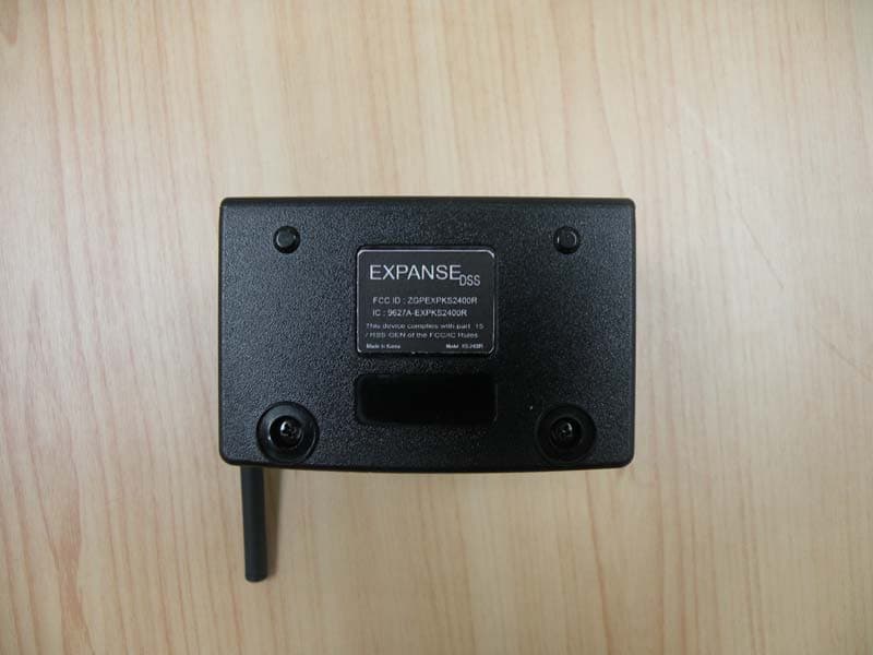
ZGPEXPKS2400R
May 16, 20112.4 GHz RF Microphone
Equipment Class
DSS - Part 15 Spread Spectrum Transmitter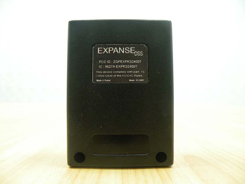
ZGPEXPKS2400T
May 12, 20112.4 GHz RF Microphone
Equipment Class
DSS - Part 15 Spread Spectrum Transmitter