ZHK-GC00007Gaming Controller
SteelSeries ApS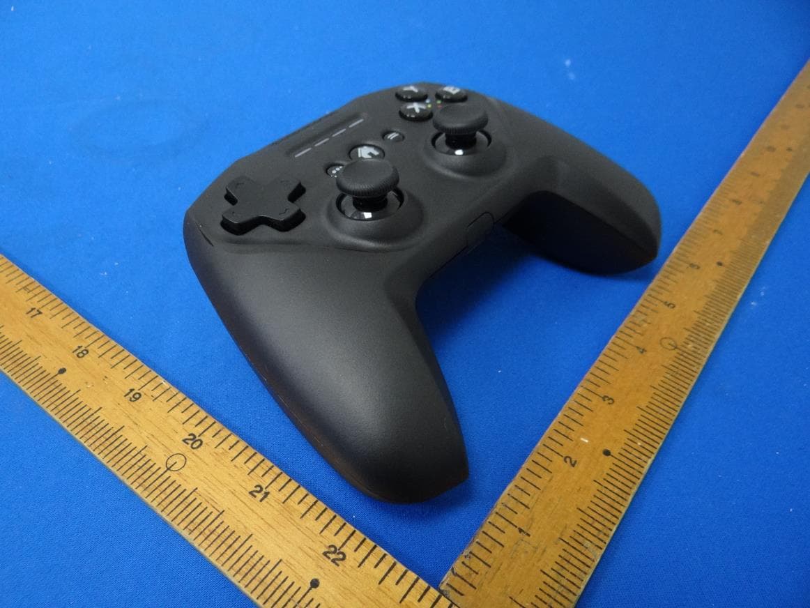
Click to zoom
Application Details
- Equipment Class
- DSS - Part 15 Spread Spectrum Transmitter
- Date of Grant
- Jan 12, 2020
- Application Purpose
- Original Equipment
- Date of Application
- Jan 12, 2020
- Equipment Note
- Gaming Controller
- Frequency Range
- 2402.00000000 - 2480.00000000
- Company
- SteelSeries ApS
- Country
- United States
Documents & Files
Document Text
Text extracted from the exhibit documents filed with the FCC. Open a document above to read the original.
Users Manual
Please download the SteelSeries Nimbus companion app from the iTunes store. PRODUCT INFORMATION GUIDE CONTENTS Product overview 3–4 Setup 5 Power 6 Translations Español 7 简体中文 13 繁體中文 15 日本語 18 한국어 20 Deutsch 23 Русский 26 Français 29 Italiano 32 Português 35 Regulatory 39 2 find help at support.steelseries.com PACKAGE CONTENTS Nimbus+ ControllerProduct Information Guide COMPATIBILITY iPhone XS Max iPhone X S iPhone XR iPhone X iPhone 8 iPhone 8 Plus iPhone 7 iPhone 7 Plus iPhone SE iPhone 6 iPhone 6 Plus iPod touch 7th generation iPad Pro (12.9-inch) 2nd & 3rd generation iPad Pro (11-inch) iPad Pro (10.5-inch) iPad Pro (9.7-inch) iPad Air 2 iPad Air 3rd generation iPad mini 4 iPad mini 5th generation iPad 5th and 6th generation Apple TV 4K Apple TV 4th generation 3 PRODUCT OVERVIEW 01 8-way D-pad 02 Options Button 03 Player Indicator LEDs 04 Menu Button 05 A, B, X, Y Buttons 06 Home Button 07 Analog Joysticks 07 0105 06 030204 L1 L2 R1 R2 4 Find accessories and replacement parts at steelseries.com/gaming-accessories 08 Phone Holder Receptacles 09 Wireless Pairing Button 10 Lightning Charge Port 11 Battery Level Button 12 R1 / L1 Shoulder Buttons 13 R2 / L2 Analog Triggers 08 09 13 10 11 08 12 5 SETUP INITIALIZATION 01 Turn on your Nimbus+ by pressing and holding the Menu Button 04 . 02 All four LEDs 03 will fade on and off slowly to indicate your Nimbus+ is in pairing mode. If not, hold the Wireless Pairing Button 09 for 3 seconds. 03 To pair your Nimbus+ to your iOS device, go to Settings → Bluetooth. “Nimbus+” will be displayed on the screen. Tap to Connect. More detailed product information at steelseries.com/nimbus-plus PAIRING TO A NEW DEVICE 01 Press the Wireless Pairing Button 09 for 3 seconds. 02 All four LEDs 03 will fade on and off slowly to indicate that your Nimbus+ is in pairing mode. RECONNECTING TO AN EXISTING DEVICE 01 Turn on your Nimbus+ by pressing and holding the Menu Button 04 . 02 During the connecting sequence, the LEDs 03 will fade on and off, cycling from 1 to 4. The Nimbus+ will automatically reconnect to the most recent device when powered on. If you want to connect to a previously paired device, simply select the Nimbus+ from the Bluetooth menu on the Apple device. 6 POWER CHARGING To charge your Nimbus+ plug an Apple Lightning Cable (not included) into the Lightning Charge Port 10 and connect it to a power source. BATTERY INDICATION On power on, your current battery level will be displayed across the four player indicator LEDs 03 for three seconds. To manually show the battery level, press the Battery Level Button 11 at any time to view your current Battery level on the four player indicator LEDs 03 . > 75 % 50 – 75 % 25 – 50 % <25 % BATTERY INDICATION When the Nimbus+ battery charge gets low (~20 minutes remaining), LED 1 will flash quickly for 10 seconds. POWERING ON/OFF To turn the controller on or off press and hold the Menu Button 04 . The controller will turn itself off after 15 minutes of inactivity. 7 ESPAÑOL CONTENIDO DEL PAQUETE Controlador de juegos Stratus Duo Cable USB Adaptador USB inalámbrico Guía de información del producto COMPATIBILIDAD ENTRE PLATAFORMAS Windows 7 + Steam y modo Big Picture en Steam Oculus Rift y Oculus Go Samsung Gear VR Android 4+ Si necesita ayuda, visite support.steelseries.com DESCRIPCIÓN GENERAL DEL PRODUCTO 01 Cruceta de control de 8 direcciones 02 Botón de retroceso/selección 03 LED indicadores de jugadores 04 Botón de avance/inicio 05 Botones A, B, X, Y 06 Botón Home 07 Joysticks analógicos 08 Adaptador USB inalámbrico 09 Cable USB 10 Interruptor de modo inalámbrico 11 Botón de conexión inalámbrica 12 Puerto micro-USB 13 Botón de nivel de batería 14 Interruptor de encendido 15 Botones gatillo R1, L1 16 Gatillos analógicos R2, L2 * Consulte accesorios y repuestos en steelseries.com/gaming-accessories CONFIGURACIÓN MODOS DE CONEXIÓN Conectar y cargar / 2.4GHz / Bluetooth PRIMEROS PASOS EN WINDOWS Y STEAM 01 Deslice el interruptor de modo inalámbrico 10 a 2,4 GHz y enchufa el adaptador USB inalámbrico 08 suministrado a un puerto USB libre del ordenador. 02 Deslice el interruptor de encendido 14 de rojo a verde para activar el Stratus Duo. 8 03 Al encenderse, se mostrará el nivel actual de la batería en los cuatro LED indicadores de jugadores 03 durante tres segundos. 04 El Stratus Duo ya está conectado con el adaptador USB inalámbrico 08 cuando lo reciba, pues no es necesario conectarlo de nuevo. 05 Ahora se encenderá el LED indicador correspondiente a su número de jugador. ¡Ya está listo para jugar! Si necesita ayuda, visite support.steelseries.com PRIMEROS PASOS EN ANDROID, SAMSUNG GEAR VR Y OCULUS GO 01 Deslice el interruptor de modo inalámbrico 10 a Bluetooth. 02 Deslice el interruptor de encendido 14 de rojo a verde para activar el Stratus Duo. 03 Al encenderse, se mostrará el nivel actual de la batería en los cuatro LED indicadores de jugadores 03 durante tres segundos. 04 Los cuatro LED parpadearán rápidamente cuando el controlador está en modo de conexión. 05 Para conectar el Stratus Duo, vaya al panel de control de Bluetooth del dispositivo en cuestión y conecte con SteelSeries Stratus Duo. 06 Si el controlador se conecta correctamente, los cuatro LED indicadores de jugadores parpadearán cada 2 segundos para indicar su estado conectado. ¡Ya está listo para jugar! VOLVER A ENLAZAR EL STRATUS DUO EN MODO BLUETOOTH El Stratus Duo recordará el último dispositivo enlazado por Bluetooth y volverá a enlazarse automáticamente. Si desea forzar que Stratus Duo vuelva a entrar en modo de enlace: 01 Pulse el botón de enlace inalámbrico 11 para entrar de nuevo en modo de enlace. O para eliminar conexiones Bluetooth anteriores. 01 Mantenga pulsado 5 segundos el botón de enlace inalámbrico 11 para eliminar la conexión Bluetooth anterior y volver a entrar en modo de enlace. 02 Los cuatro LED parpadearán rápidamente cuando esté en modo de enlace. 03 Acceda al panel de control de Bluetooth de su dispositivo y elija SteelSeries…
Text truncated - open the document above for the full version.
Cover Letter(s)
SteelSeries ApS. 656 W Randolph St., Suite 3E, Chicago, Illinois, 60661, United States DATE : 2020/01/03 FCC ID: ZHK-GC00007 Dear Sir, I hereby have entrusted the following person to be a proxy regarding application for Type Certification. Company name: Cerpass Technology Corporation Address: No.10, Lane 2, Lianfu Street, Luzhu Dist., Taoyuan City, 33848, Taiwan(R.O.C.) Name: Delia Feng For instances where our authorized agent signs the application for certification on our behalf, I acknowledge that all responsibility for complying with the terms and conditions for certification, as specified by Nemko Canada Inc, still resides with us. Signature FCC grantee contact person information. Name/Title: Chirky Lin / Regulatory Matter Manager Company Name: SteelSeries ApS. Address: 656 W Randolph St., Suite 3E, Chicago, Illinois, United States, 60661 TEL: +886 2 82263858#317 FAX: +886 2 82263626 Email: [email protected]
Cover Letter(s)
SteelSeries ApS. 656 W Randolph St., Suite 3E, Chicago, Illinois, 60661, United States DATE : 2020/01/03 Equipment Autorisation Division Federal Communications Commission 7435 Oakland Mills Road Columbia, MD 21046 FCC ID: ZHK-GC00007 Request for Confidentiality Pursuant to Sections 0.457 and 0.459 of the commissions rules, we hereby request that the following documents be held confidential: (List here the documents for which you are seeking confidentiality – for example ...) • Schematics • Block diagram • Operation description These materials contain trade secrets and proprietary information and are not customarily released to the public. The public disclosure of this information might be harmful to the company and provide unjustified benefits to our competitors. Signature FCC grantee contact person information. Name/Title: Chirky Lin / Regulatory Matter Manager Company Name: SteelSeries ApS. Address: 656 W Randolph St., Suite 3E, Chicago, Illinois, United States, 60661 TEL: +886 2 82263858#317 FAX: +886 2 82263626 Email: [email protected]
External Photos
CERPASS TECHNOLOGY CORP. Report No.: 1908189 Cerpass Technology Corp. Issued Date : Dec. 25, 2019 Page No. : 1 of 5 Photographs of EUT CERPASS TECHNOLOGY CORP. Report No.: 1908189 Cerpass Technology Corp. Issued Date : Dec. 25, 2019 Page No. : 2 of 5 CERPASS TECHNOLOGY CORP. Report No.: 1908189 Cerpass Technology Corp. Issued Date : Dec. 25, 2019 Page No. : 3 of 5 CERPASS TECHNOLOGY CORP. Report No.: 1908189 Cerpass Technology Corp. Issued Date : Dec. 25, 2019 Page No. : 4 of 5 CERPASS TECHNOLOGY CORP. Report No.: 1908189 Cerpass Technology Corp. Issued Date : Dec. 25, 2019 Page No. : 5 of 5
ID Label/Location Info
Des.: Product labelDesign: CarolScale: 1:1Unit: mmP/N: Nimbus 2 NOTES: 1. Material: Art paper 80gsm, matte coating( with glue) 2. Background color: Black 3. Text color: Pantone cool gray 4c
Internal Photos
CERPASS TECHNOLOGY CORP. Report No.: 1908189 Cerpass Technology Corp. Issued Date : Dec. 25, 2019 Page No. : 1 of 4 Photographs of EUT CERPASS TECHNOLOGY CORP. Report No.: 1908189 Cerpass Technology Corp. Issued Date : Dec. 25, 2019 Page No. : 2 of 4 Antenna position CERPASS TECHNOLOGY CORP. Report No.: 1908189 Cerpass Technology Corp. Issued Date : Dec. 25, 2019 Page No. : 3 of 4 Antenna position RF Chip CERPASS TECHNOLOGY CORP. Report No.: 1908189 Cerpass Technology Corp. Issued Date : Dec. 25, 2019 Page No. : 4 of 4
RF Exposure Info
CERPASS TECHNOLOGY CORP. Report No.: TEFB1908189 Cerpass Technology Corp. Issued date : Dec. 25, 2019 T-FD-507-0 Ver 1.2 Page No. : 57 of 58 FCC ID. : ZHK-GC00007 13. Radio Frequency Exposure 13.1 Applicable Standards The measurements shown in this test report were made in accordance with the procedures given in FCC Part 2 (Section 2.1093) LIMIT KDB 447498 D01 § 4.3(a) For 100 MHz to 6 GHz and test separation distances ≤ 50 mm, the 1-g and 10-g SAR test exclusion thresholds are determined by the following: [(max. power of channel, including tune-up tolerance, mW) / (min. test separation distance, mm)] · [√f(GHz)] ≤ 3.0 for 1-g SAR, and ≤ 7.5 for 10-g extremity SAR, where *f(GHz) is the RF channel transmit frequency in GHz * Power and distance are rounded to the nearest mW and mm before calculation *The result is rounded to one decimal place for comparison *The values 3.0 and 7.5 are referred to as numeric thresholds in step b) below The test exclusions are applicable only when the minimum test separation distance is ≤ 50 mm, and for transmission frequencies between 100 MHz and 6 GHz. When the minimum test separation distance is < 5 mm, a distance of 5 mm according to 4.1 f) is applied to determine SAR test exclusion 13.2 EUT Specification Frequency band (Operating) WLAN: 2412MHz ~ 2462MHz Bluetooth: 2402MHz ~ 2480MHz Device category Portable (<20cm separation) Mobile (>20cm separation) Exposure classification Occupational/Controlled exposure General Population/Uncontrolled exposure Antenna diversity Single antenna Multiple antennas Tx diversity Rx diversity Tx/Rx diversity Evaluation applied MPE Evaluation* SAR Evaluation N/A Remark: 1. The maximum conducted output power is 2.02dBm (1.592mW) at 2480MHz (with 1.89dBi antenna gain.) 2. DTS device is not subject to routine RF evaluation; MPE estimate is used to justify the compliance. 3. For mobile or fixed location transmitters, no SAR consideration applied. CERPASS TECHNOLOGY CORP. Report No.: TEFB1908189 Cerpass Technology Corp. Issued date : Dec. 25, 2019 T-FD-507-0 Ver 1.2 Page No. : 58 of 58 FCC ID. : ZHK-GC00007 TEST RESULTS According to the KDB447498: The SAR test exclusion thresholds Level: [(max. power of channel, including tune-up tolerance, mW) /(min. test separation distance, mm)] * sqrt (freq. in GHz) < 3 Calculation Modulation Mode Channel Frequency (MHz) Max. Conducted output power (dBm) Max. Tune up power (dBm) Max. Tune up power (mW) Distance (mm) SAR test exclusion thresholds (mW) GFSK 2402-2480 2.02 4.02 2.52 5 10.0000 π/4-DQPSK 2402-2480 -0.18 1.82 1.52 5 10.0000 8DPSK 2402-2480 0.52 2.52 1.79 5 10.0000 Since the source-based time-averaging conducted output power is well below the SAR low threshold level, so the EUT is considered to comply with SAR requirement without testing.
Test Report
CERPASS TECHNOLOGY CORP. Report No.: TEFB1908189 Cerpass Technology Corp. Issued date : Dec. 25, 2019 T-FD-507-0 Ver 1.2 Page No. : 1 of 58 FCC ID. : ZHK-GC00007 FCC RADIO TEST REPORT Applicant : SteelSeries ApS. Address : 656 W Randolph St., Suite 3E Chicago, IL 60661, USA Equipment : Gaming Controller Model No. : GC-00007 Trade Name : FCC ID. : ZHK-GC00007 I HEREBY CERTIFY THAT : The sample was received on Aug. 27, 2019 and the testing was completed on Dec. 23, 2019 at Cerpass Technology Corp. The test result refers exclusively to the test presented test model / sample. Without written approval of Cerpass Technology Corp., the test report shall not be reproduced except in full. Approved by: Mark Liao / Supervisor Laboratory Accreditation: Cerpass Technology Corporation Test Laboratory CERPASS TECHNOLOGY CORP. Report No.: TEFB1908189 Cerpass Technology Corp. Issued date : Dec. 25, 2019 T-FD-507-0 Ver 1.2 Page No. : 2 of 58 FCC ID. : ZHK-GC00007 Contents 1. Summary of Test Procedure and Test Results ................................................................................. 5 1.1 Applicable Standards ................................................................................................................. 5 2. Test Configuration of Equipment under Test ................................................................................... 6 2.1 Feature of Equipment under Test ............................................................................................... 6 2.2 Carrier Frequency of Channes ................................................................................................... 6 2.3 Test Mode & Test Software ........................................................................................................ 7 2.4 Description of Test System ......................................................................................................... 7 2.5 General Information of Test ........................................................................................................ 8 2.6 Measurement Uncertainty .......................................................................................................... 8 3. Test Equipment and Ancillaries Used for Tests ............................................................................... 9 4. Antenna Requirements ..................................................................................................................... 11 4.1 Standard Applicable ................................................................................................................. 11 4.2 Antenna Construction and Directional Gain ............................................................................. 11 5. Test of AC Power Line Conducted Emission ................................................................................. 12 5.1 Test Limit .................................................................................................................................. 12 5.2 Test Procedures ....................................................................................................................... 12 5.3 Typical Test Setup .................................................................................................................... 13 5.4 Test Result and Data ................................................................................................................ 14 5.5 Test Photographs ..................................................................................................................... 16 6. Test of Radiated Spurious Emission ............................................................................................... 17 6.1 Test Limit .................................................................................................................................. 17 6.2 Test Procedures ....................................................................................................................... 17 6.3 Typical Test Setup ................................................................................................................... 18 6.4 Test Result and Data (9kHz ~ 30MHz)..................................................................................... 19 6.5 Test Result and Data (30MHz ~ 1GHz).................................................................................... 19 6.6 Test Result and Data (1GHz ~ 25GHz) .................................................................................... 21 6.7 Restricted Bands of Operation ................................................................................................. 33 6.8 Test Photographs (30MHz ~ 1GHz) ......................................................................................... 34 6.9 Test Photographs (1GHz ~ 25GHz) ......................................................................................... 35 7. Test of Conducted Spurious Emission ........................................................................................... 36 7.1 Test Limit .................................................................................................................................. 36 7.2 Test Procedure ......................................................................................................................... 36 7.3 Test Setup Layout .................................................................................................................... 36 7.4 Test Result and Data ................................................................................................................ 36 8. 20dB Bandwidth Measurement Data ............................................................................................... 44 8.1 Test Limit .................................................................................................................................. 44 8.2 Test Procedures ........................................................…
Text truncated - open the document above for the full version.
Test Setup Photos
CERPASS TECHNOLOGY CORP. Report No.: TEFB1908189 Cerpass Technology Corp. Issued date : Dec. 25, 2019 T-FD-507-0 Ver 1.2 Page No. : 16 of 58 FCC ID. : ZHK-GC00007 5.5 Test Photographs Front View Rear View CERPASS TECHNOLOGY CORP. Report No.: TEFB1908189 Cerpass Technology Corp. Issued date : Dec. 25, 2019 T-FD-507-0 Ver 1.2 Page No. : 34 of 58 FCC ID. : ZHK-GC00007 6.8 Test Photographs (30MHz ~ 1GHz) Front View Rear View CERPASS TECHNOLOGY CORP. Report No.: TEFB1908189 Cerpass Technology Corp. Issued date : Dec. 25, 2019 T-FD-507-0 Ver 1.2 Page No. : 35 of 58 FCC ID. : ZHK-GC00007 6.9 Test Photographs (1GHz ~ 25GHz) Front View Rear View
Contact Information
Applicant
Chirky Lin(Regulatory Matter Manager)
Test Firm
Cerpass Technology Corporation Test LaboratoryBen Wang
Technical Specifications
| # | Rule Parts | Frequency Range | Power Output |
|---|---|---|---|
| 1 | 15C | 2.40 GHz - 2.48 GHz | 1.60 mW |
Other Applications from SteelSeries ApS
ZHK-GC10
Jun 23, 2026Gaming Controller
Equipment Class
DSS - Part 15 Spread Spectrum TransmitterZHK-HS35TXXP
May 22, 2026Transceiver
Equipment Class
DTS - Digital Transmission SystemZHK-HS35TXP
May 14, 2026Transceiver
Equipment Class
DTS - Digital Transmission SystemZHK-M031
May 10, 2026Wireless Mouse
Equipment Class
UWB - Ultra Wideband TransmitterZHK-M034
May 05, 2026Wireless Mouse
Equipment Class
UWB - Ultra Wideband Transmitter