ZHK-M00019TXTransceiver
SteelSeries ApS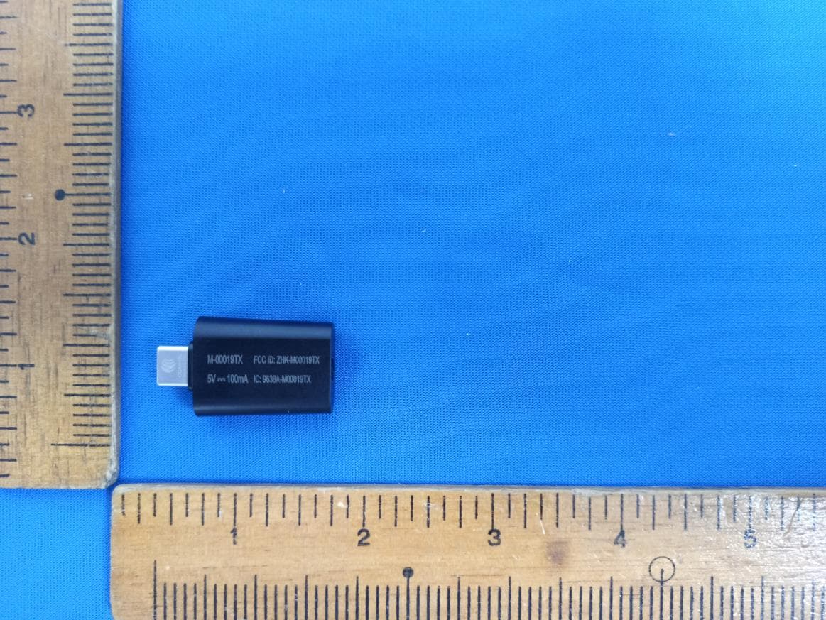
Click to zoom
Application Details
- Equipment Class
- DTS - Digital Transmission System
- Date of Grant
- Sep 20, 2020
- Application Purpose
- Original Equipment
- Date of Application
- Sep 17, 2020
- Equipment Note
- Transceiver
- Frequency Range
- 2402.00000000 - 2480.00000000
- Company
- SteelSeries ApS
- Country
- United States
Documents & Files
Document Text
Text extracted from the exhibit documents filed with the FCC. Open a document above to read the original.
Users Manual
PRODUCT INFORMATION GUIDE AEROX 3 WIRELESS CONTENTS Product overview 6 –7 Setup 8 Connecting via 2.4 GHz wireless Pairing via Bluetooth Battery level indicator 9 Translations Español 10 简体中文 12 繁體中文 14 日本語 16 한국어 18 Deutsch 20 Русский 22 Français 24 Italiano 26 Português 28 Regulatory 30 3 WELCOME TO AEROX 3 Your new mouse is the result of our unyielding pursuit of perfection for over 15 years. We poured our hearts into creating the best possible ultra lightweight gaming mouse, optimizing it for speed and performance. The SteelSeries Aerox 3 is engineered to get the fastest swipes, so you can beat the competition to the trigger. When milliseconds count, speed matters. STEELSERIES ENGINE 4 STEELSERIES ENGINE To enjoy GameSense integration, program macros, and customize lighting effects and other mouse settings on your new Aerox 3 Wireless mouse, download SteelSeries Engine at steelseries.com/engine 5 find help at support.steelseries.com PACKAGE CONTENTS Aerox 3 Wireless Mouse USB Type-C to USB Type-A Super Mesh Data/Charging Cable (5’9”/1,8 m) USB Type-C Wireless Dongle Extension Adapter Product Information Guide SYSTEM REQUIREMENTS / COMPATIBILITY PC Mac Xbox STEELSERIES ENGINE SOFTWARE REQUIRE- MENTS Platforms Windows 7+ Mac OS X 10.13+ 160 MB of free hard drive space for installation OFF 2.4G 7 7 9 8 3 5 6 4 12 10 1112 6 PRODUCT OVERVIEW 1 Left Trigger 2 Right Trigger 3 Scroll Wheel 4 CPI Button 5 Side Button 1 6 Side Button 2 OFF 2.4G 7 7 9 8 3 5 6 4 12 10 1112 7 Find accessories and replacement parts at steelseries.com/gaming-accessories 7 PTFE Feet 8 Wireless Mode Switch 9 TrueMove Air Sensor 10 USB Type-C to USB Type-A Super Mesh Data/Charging Cable 11 USB Type-C Wireless Dongle 12 Extension Adapter 8 SETUP More detailed product information at steelseries.com/aerox-3-wireless CONNECTING VIA 2.4 GHZ WIRELESS 1 Connect the Aerox 3 Wireless Dongle 11 to an available USB port on your device. 2 Toggle the Wireless Mode Switch 8 to the “2.4 GHz” position. 3 The mouse and dongle will automatically pair. 4 To further customize your mouse, or re-pair a Wireless Dongle 11 , download the SteelSeries Engine software from steelseries.com/engine PAIRING VIA BLUETOOTH 1 Initiate Bluetooth pairing mode on your Bluetooth 5.0 or higher enabled device. 2 Hold the CPI Button 4 and toggle the Wireless Mode Switch 8 to the Bluetooth position to turn on your mouse. 3 The Mouse lighting will start blinking blue when searching for a connection. 4 Select “Aerox 3 Wireless” on your Bluetooth-enabled device. 9 BATTERY LEVEL INDICATOR The mouse lighting will flash yellow to notify you about battery life: 5 minute intervals 2 hours of battery remaining 2 minute intervals 1.5 hours of battery remaining 1 minute interval 1 hour of battery remaining When charging, the lighting will flash green for 10 seconds, before resuming default lighting. 10 ESPAÑOL CONTENIDO DE LA CAJA Ratón inalámbrico Aerox 3 Cable de carga/datos Super Mesh USB tipo C a USB tipo A (5'9"/1,8 m) Adaptador inalámbrico USB tipo C Adaptador de extensión Guía de información sobre el producto REQUISITOS DEL SISTEMA/ COMPATIBILIDAD PC / Mac / Xbox REQUISITOS DE SOFTWARE DEL MOTOR STEELSERIES Plataformas Windows 7 o superior Mac OS X 10.13 o superior 160 MB de espacio libre en disco duro para la instalación * Ayuda en support.steelseries.com VISTA GENERAL DEL PRODUCTO 1 Gatillo izquierdo 2 Gatillo derecho 3 Rueda de desplazamiento 4 Botón CPI 5 Botón lateral 1 6 Botón lateral 2 7 Pies de PTFE 8 Interruptor de modo inalámbrico 9 Sensor TrueMove Air 10 Cable de carga/datos Super Mesh USB tipo C a USB tipo A 11 Adaptador inalámbrico USB tipo C 12 Adaptador de extensión * Podrás encontrar accesorios y piezas de repuesto en steelseries.com/gaming-accessories 11 CONFIGURACIÓN CONEXIÓN VÍA INALÁMBRICA A 2,4 GHZ 1 Conecta el adaptador inalámbrico Aerox 3 11 a un puerto USB disponible en tu dispositivo. 2 Cambia el interruptor de modo inalámbrico 8 a la posición "2,4 GHz". 3 El ratón y el adaptador se emparejarán automáticamente. 4 Para personalizar aún más tu ratón o volver a emparejar el adaptador inalámbrico 11 , descarga el software SteelSeries Engine de steelseries.com/engine * Información más detallada sobre el producto en steelseries.com/aerox-3-wireless EMPAREJAMIENTO VÍA BLUETOOTH 1 Inicia el modo de empareja- miento Bluetooth en el dispo sitivo con Bluetooth 5.0 o posterior. 2 Mantén presionado el botón CPI 4 y cambia el interruptor de modo inalámbrico 8 a la posición Bluetooth para encender el ratón. 3 La iluminación del ratón comenzará a parpadear en azul cuando busque una conexión. 4 Selecciona "Aerox 3 Wireless" en el dispositivo con Bluetooth. INDICADOR DE NIVEL DE BATERÍA La iluminación del ratón parpadeará en amarillo para informar de la duración de la batería: 5 minutos (frecuencia) 2 horas restantes de batería 2 minutos (frecuencia) 1.5 horas restantes de batería 1 minuto (frecuencia) 1 hora restante de batería Durante la carga, la iluminación parpadeará en verde durante 10 segundos antes de reanudar la iluminación predeterminada. 12 简体中文 包装内容 Aerox 3 无线鼠标 USB Type-C 到 USB Type-A 卓越的编织数据传输/充电线 (5’9”/1.8 m) USB Type-C 无线适配器 扩展适配器 产品信息指南 系统要求 / 兼容性 PC / Mac / Xbox STEELSERIES ENGINE 软件要求 平台 Windows 7 + Mac OS X 10.13+ 160 MB 可用硬盘空间供安装使用 * 访问 support.steelseries.com 获取帮助 产品概览 1 左触发器 2 右触发器 3 滚轮 4 CPI 按钮 5 侧部按钮 1 6 侧部按钮 2 7 PTFE 脚貼 8 无线模式开关 9 TrueMove Air 传感器 10 USB Type-C 到 USB Type-A 卓越的编织数据传输/充电线 11 USB Type-C 无线适配器 12 扩展适配器 * 如需配件和更换部件,请访问 steelseries.com/gaming- accessories 13 设置 连接 VIA 2.4 GHZ 无线 1 将 Aerox 3 无线适配器 11 连接 至设备的 USB 端口。 2 将无线模式开关切换 8 至“2.4 GHz”位置。 3 鼠标和适配器将自动配对。 4 要进一步定制您的鼠标或为无 线适配器重新配对 11 ,请从 steelseries.com/engine 下载 SteelSeries Engine 软件 * 更多产品信息请访问 steelseries.com/aerox-3-wireless 通过蓝牙配对 1 在启用蓝牙 5.0 或更高版本的 设备上启动蓝牙配对模式。 2 按住 CPI 按钮 4 ,将无线模式 开关切换 8 至蓝牙位 置 ,打 开鼠标。 3 搜索连接时,鼠标灯将开始闪 烁蓝光。 4 在启用蓝牙的设备上选 择“Aerox 3 Wireless”。 电池电量指示灯 鼠标灯将呈黄色闪烁,通知您电 池寿命: 5 分钟间隔 2 电池剩余小时数 2 分钟间隔 1.5 电池剩余小时数 1 分钟 间隔 1 电池剩余小时数 充电时,将呈绿色闪烁 10 秒钟,然 后恢复默认点…
Text truncated - open the document above for the full version.
Cover Letter(s)
Rev 11/20/07 Federal Communications Commission Authorization and Evaluation Division Confidentiality Request regarding application for certification of FCC ID: ZHK-M00019TX. Pursuant to Sections 0.457 and 0.459 of the Commission’s Rules, we hereby request confidential treatment of information accompanying this application as outlined below: long-term confidentiality Exhibit TypeFile Name Block DiagramBlock Diagram,pdf Operational DescriptionOperational Description.pdf Schematic DiagramsSchematic,pdf Internal photosInternal Photos-M-00019TX.pdf Justification for internal photos: The EUT use ultrasonic welding, the Circuit board(s) or internal components are inaccessible to the user The above materials contain trade secrets and proprietary information not customarily released to the public. The public disclosure of these materials may be harmful to the applicant and provide unjustified benefits to its competitors. The applicant understands that pursuant to Section 0.457 of the Rules, disclosure of this application and all accompanying documentation will not be made before the date of the Grant for this application. Pursuant to DA04-1705 June 15, 2004 of the Commission’s public notice, we also request temporary confidential treatment of information accompanying this application as outlined below: short-term confidentiality Exhibit TypeFile Name External PhotosExternal Photos-M-00019.pdf User’s ManualUser Manual.pdf Test Set-up PhotosTest Setup Photos.pdf Sincerely, Chirky Lin/ Regulatory Matter Manager SteelSeries ApS
Cover Letter(s)
RF_160, Issue 02 Declaration of Authorization We Name:SteelSeries ApS. Address:656 W Randolph St., Suite 3E City:Chicago, Illinois 60661 Country:United States Declare that: Name Representative of agent: Delia Feng (1) Agent Company name:Cerpass Technology Corporation Address:No.10, Lane 2, Lianfu Street, Luzhu Dist., City:Taoyuan City 33848 Country:Taiwan, R.O.C. is authorized to apply for Certification of the following product(s): Product description: Transceiver Type designation:M-00019TX Trademark:steelseries on our behalf. Date:Aug. 31, 2020 City:Chicago Name:Chirky Lin (2) Function:Regulatory Matter Manager Signature: Notes: (1): Required for FCC application (2): For FCC it must be the Grantee Code “owner” or the authorized agent.
Cover Letter(s)
ACX Advanced Ceramic X AT8010 Series Multilayer Chip Antenna Features Monolithic SMD with small, low-profile and light-weight type. Wide bandwidth Applications 2.4GHz WLAN, Home RF, Bluetooth Modules, etc. Specifications Part Number Frequency Range (MHz) Peak Gain (dBi typ.) Average Gain (dBi typ.) VSWR Impedance AT8010 -E2R9HAA_ 2400~2500 2.5 (XZ-V) 0.5 (XZ-V) 2 max. 50 Ω Q’ty/Reel (pcs) : 1,000 pcs Operating Temperature Range : -40 ~ +85 o C Storage Temperature Range : -40 ~ +85 o C Power Capacity : 3W max. Part Number AT 8010 - E 2R9 HAA dc efgh c Type AT : Antenna d Dimensions ( L × W ) 8.0 × 1.0 mm e Material Code E f Frequency Range 2R9=2900MHz g Specification Code HAA h Packaging T: Tape & Reel B: Bulk Terminal Configuration No. Terminal Name No. Terminal Name c Feeding Point d NC d c ACX Advanced Ceramic X Dimensions and Recommended PC Board Pattern Unit : mm L W a1 T a2 Mark L W T a1 a2 Dimensions 8.00.2 1.00.2 1.00.2 0.50.2 1.00.2 With Matching Circuits (Unit in mm) Feeding line No Ground 2.7 nH 1 pF Ground 1 1 7 1.5 1 (Matching circuit and component values will be different, depending on PCB layout) *Line width should be designed to match 50Ω characteristic impedance, depending on PCB material and thickness. ACX Advanced Ceramic X Typical Electrical Characteristics (T=25 o C) Test Board (Unit in mm) Feeding line Matching circuits Ground 2 0 12 Antenna No Ground 40 Return Loss / With Matching Circuits ACX Advanced Ceramic X Radiation Patterns XZ cut @2.45GHz Vertical Horizontal YZ cut @2.45GHz Vertical Horizontal XZ-V/XZ-H YZ-V/YZ-H XY cut @2.45GHz Vertical Horizontal Z 270 o 0 o X Y XY-cut scanning direction Y 270 o 0 o X Z XZ-cut scanning direction X 270 0 o Z Y YZ-cut scanning direction Advanced Ceramic X Corp. 16 Tzu Chiang Road, Hsinchu Industrial District Hsinchu Hsien 303, Taiwan TEL:886-3-5987008 FAX:886-3-5987001 E-mail: [email protected] http://www.acxc.com.tw 180 180 180 o XY-V/XY-H 90 o 90 o 90 o
External Photos
CERPASS TECHNOLOGY CORP. Report No.: 2007049 Cerpass Technology Corp. Issued Date : Aug. 14, 2020 Page No. : 1 of 8 Photographs of EUT CERPASS TECHNOLOGY CORP. Report No.: 2007049 Cerpass Technology Corp. Issued Date : Aug. 14, 2020 Page No. : 2 of 8 CERPASS TECHNOLOGY CORP. Report No.: 2007049 Cerpass Technology Corp. Issued Date : Aug. 14, 2020 Page No. : 3 of 8 CERPASS TECHNOLOGY CORP. Report No.: 2007049 Cerpass Technology Corp. Issued Date : Aug. 14, 2020 Page No. : 6 of 8 CERPASS TECHNOLOGY CORP. Report No.: 2007049 Cerpass Technology Corp. Issued Date : Aug. 14, 2020 Page No. : 7 of 8 CERPASS TECHNOLOGY CORP. Report No.: 2007049 Cerpass Technology Corp. Issued Date : Aug. 14, 2020 Page No. : 8 of 8
ID Label/Location Info
Label & Location Rear side of EUT M-00019TX FCC ID: ZHK-M00019TX IC: 9638A-M00019TX
RF Exposure Info
CERPASS TECHNOLOGY CORP. Report No.: TEFI2007049-512 Cerpass Technology Corp. Issued date : Aug. 26, 2020 T-FD-508-0 Ver 1.3 Page No. : 41 of 42 FCC ID : ZHK-M00019TX 12. Radio Frequency Exposure 12.1 Applicable Standards The measurements shown in this test report were made in accordance with the procedures given in FCC Part 2 (Section 2.1093) LIMIT KDB 447498 D01 § 4.3(a) For 100 MHz to 6 GHz and test separation distances ≤ 50 mm, the 1-g and 10-g SAR test exclusion thresholds are determined by the following: [(max. power of channel, including tune-up tolerance, mW) / (min. test separation distance, mm)] · [√f(GHz)] ≤ 3.0 for 1-g SAR, and ≤ 7.5 for 10-g extremity SAR, where *f(GHz) is the RF channel transmit frequency in GHz * Power and distance are rounded to the nearest mW and mm before calculation *The result is rounded to one decimal place for comparison *The values 3.0 and 7.5 are referred to as numeric thresholds in step b) below The test exclusions are applicable only when the minimum test separation distance is ≤ 50 mm, and for transmission frequencies between 100 MHz and 6 GHz. When the minimum test separation distance is < 5 mm, a distance of 5 mm according to 4.1 f) is applied to determine SAR test exclusion 12.2 EUT Specification Frequency band (Operating) 2.4G: 2412MHz ~ 2462MHz BLE: 2402MHz ~ 2480MHz Device category Portable (<20cm separation) Mobile (>20cm separation) Exposure classification Occupational/Controlled exposure General Population/Uncontrolled exposure Antenna diversity Single antenna Multiple antennas Tx diversity Rx diversity Tx/Rx diversity Evaluation applied MPE Evaluation* SAR Evaluation N/A Remark: 1. The maximum output power is -2.32 dBm (0.586mW) at 2402MHz (with 2.50 dBi antenna gain.) 2. DTS device is not subject to routine RF evaluation; MPE estimate is used to justify the compliance. 3. For mobile or fixed location transmitters, no SAR consideration applied. CERPASS TECHNOLOGY CORP. Report No.: TEFI2007049-512 Cerpass Technology Corp. Issued date : Aug. 26, 2020 T-FD-508-0 Ver 1.3 Page No. : 42 of 42 FCC ID : ZHK-M00019TX 12.3 Test Results According to the KDB447498: The SAR test exclusion thresholds Level: [(max. power of channel, including tune-up tolerance, mW) /(min. test separation distance, mm)] * sqrt (freq. in GHz) < 3 Channel Frequency (MHz) Max. Conducted output power (dBm) Max. Tune up power (dBm) Max. Tune up power (mW) Distance (mm) SAR test exclusion thresholds (mW) 2402-2480 -2.32 -0.32 0.93 5 10.00 Since the source-based time-averaging conducted output power is well below the SAR low threshold level, so the EUT is considered to comply with SAR requirement without testing
Test Report
CERPASS TECHNOLOGY CORP. Report No.: TEFI2007049-512 Cerpass Technology Corp. Issued date : Aug. 26, 2020 T-FD-508-0 Ver 1.3 Page No. : 1 of 42 FCC ID : ZHK-M00019TX FCC RADIO TEST REPORT Applicant : SteelSeries ApS. Address : 656 W Randolph St., Suite 3E Chicago, IL 60661, USA Equipment : Transceiver Model No. : M-00019TX Trade Name : FCC ID. : ZHK-M00019TX I HEREBY CERTIFY THAT : The sample was received on Jul. 06, 2020 and the testing was completed on Aug. 08, 2020 at Cerpass Technology Corp. The test result refers exclusively to the test presented test model / sample. Without written approval of Cerpass Technology Corp., the test report shall not be reproduced except in full. Approved by: Mark Liao / Supervisor Laboratory Accreditation: Cerpass Technology Corporation Test Laboratory CERPASS TECHNOLOGY CORP. Report No.: TEFI2007049-512 Cerpass Technology Corp. Issued date : Aug. 26, 2020 T-FD-508-0 Ver 1.3 Page No. : 2 of 42 FCC ID : ZHK-M00019TX Contents 1. Summary of Test Procedure and Test Results ................................................................................. 5 1.1 Applicable Standards ................................................................................................................. 5 2. Test Configuration of Equipment under Test ................................................................................... 6 2.1 Feature of Equipment under Test ............................................................................................... 6 2.2 Carrier Frequency of Channels .................................................................................................. 6 2.3 Test Mode and Test Software ..................................................................................................... 7 2.4 Description of Test System ......................................................................................................... 7 2.5 General Information of Test ........................................................................................................ 8 2.6 Measurement Uncertainty .......................................................................................................... 8 3. Test Equipment and Ancillaries Used for Tests ............................................................................... 9 4. Antenna Requirements ..................................................................................................................... 11 4.1 Standard Applicable ................................................................................................................. 11 4.2 Antenna Construction and Directional Gain ............................................................................. 11 5. Test of AC Power Line Conducted Emission ................................................................................. 12 5.1 Test Limit .................................................................................................................................. 12 5.2 Test Procedures ....................................................................................................................... 12 5.3 Typical Test Setup .................................................................................................................... 13 5.4 Test Result and Data ................................................................................................................ 14 5.5 Test Photographs ..................................................................................................................... 16 6. Test of Radiated Spurious Emission ............................................................................................... 17 6.1 Test Limit .................................................................................................................................. 17 6.2 Test Procedures ....................................................................................................................... 17 6.3 Typical Test Setup .................................................................................................................... 18 6.4 Test Result and Data (9KHz ~ 30MHz) .................................................................................... 19 6.5 Test Result and Data (30MHz ~ 1GHz) .................................................................................... 19 6.6 Test Result and Data (1GHz ~ 25GHz) .................................................................................... 21 6.7 Restricted Bands of Operation ................................................................................................. 27 6.8 Test Photographs (30MHz ~ 1GHz) ......................................................................................... 28 6.9 Test Photographs (1GHz ~ 25GHz) ......................................................................................... 29 7. Test of Conducted Spurious Emission ........................................................................................... 31 7.1 Test Limit .................................................................................................................................. 31 7.2 Test Procedure ......................................................................................................................... 31 7.3 Test Setup Layout .................................................................................................................... 31 7.4 Test Result and Data ................................................................................................................ 31 8. On Time, Duty Cycle and Measurement methods ......................................................................... 34 8.1 Test Limit .................................................................................................................................. 34 8.2 Test Procedure ..............................................................…
Text truncated - open the document above for the full version.
Test Setup Photos
CERPASS TECHNOLOGY CORP. Report No.: TEFI2007049-512 Cerpass Technology Corp. Issued date : Aug. 26, 2020 T-FD-508-0 Ver 1.3 Page No. : 16 of 42 FCC ID : ZHK-M00019TX 5.5 Test Photographs Front View Rear View CERPASS TECHNOLOGY CORP. Report No.: TEFI2007049-512 Cerpass Technology Corp. Issued date : Aug. 26, 2020 T-FD-508-0 Ver 1.3 Page No. : 28 of 42 FCC ID : ZHK-M00019TX 6.8 Test Photographs (30MHz ~ 1GHz) Front View Rear View CERPASS TECHNOLOGY CORP. Report No.: TEFI2007049-512 Cerpass Technology Corp. Issued date : Aug. 26, 2020 T-FD-508-0 Ver 1.3 Page No. : 29 of 42 FCC ID : ZHK-M00019TX 6.9 Test Photographs (1GHz ~ 25GHz) Front View Rear View CERPASS TECHNOLOGY CORP. Report No.: TEFI2007049-512 Cerpass Technology Corp. Issued date : Aug. 26, 2020 T-FD-508-0 Ver 1.3 Page No. : 30 of 42 FCC ID : ZHK-M00019TX Side View
Contact Information
Applicant
Chirky Lin(Regulatory Matter Manager)
Technical Contact
SteelSeries ApS.Chirky Lin
[email protected]886 2 82263858
656 W Randolph St., Suite 3E · United States
Non-Technical Contact
Cerpass Technology CorporationDelia Feng
[email protected]886-3-3226-888
Test Firm
Cerpass Technology Corporation Test LaboratoryBen Wang
Technical Specifications
| # | Rule Parts | Frequency Range | Power Output |
|---|---|---|---|
| 1 | 15C | 2.40 GHz - 2.48 GHz | 600.00 µW |
Other Applications from SteelSeries ApS
ZHK-GC10
Jun 23, 2026Gaming Controller
Equipment Class
DSS - Part 15 Spread Spectrum TransmitterZHK-HS35TXXP
May 22, 2026Transceiver
Equipment Class
DTS - Digital Transmission SystemZHK-HS35TXP
May 14, 2026Transceiver
Equipment Class
DTS - Digital Transmission SystemZHK-M031
May 10, 2026Wireless Mouse
Equipment Class
UWB - Ultra Wideband TransmitterZHK-M034
May 05, 2026Wireless Mouse
Equipment Class
UWB - Ultra Wideband Transmitter