ZHZDRAGINOMS12802.11b/g wireless sensor node
Dragino Technology Co., Limited.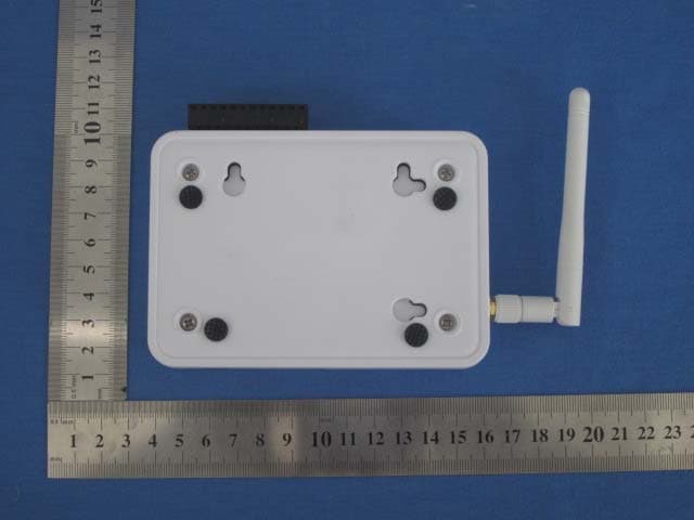
Click to zoom
Application Details
- Equipment Class
- DTS - Digital Transmission System
- Date of Grant
- Jun 12, 2011
- Application Purpose
- Original Equipment
- Date of Application
- Jun 12, 2011
- Equipment Note
- 802.11b/g wireless sensor node
- Frequency Range
- 2412.00000000 - 2462.00000000
- Country
- China
Documents & Files
Document Text
Text extracted from the exhibit documents filed with the FCC. Open a document above to read the original.
Users Manual
www.dragino.cn 1/ MS12 User Manual www.dragino.cn 2/ 1 Introduce..................................................................................................................................3 2 Configure the device via GUI...................................................................................................4 2.1 Access the GUI......................................................................................................................4 2.2 Configure Wifi parameters.................................................................................................4 2.3 Network setting....................................................................................................................5 2.4 System Status:.......................................................................................................................6 3 Securing the MS12..................................................................................................................6 4 Attaching the current clamp....................................................................................................7 5 Connecting the clamp sensor cable........................................................................................7 6 Powering Up............................................................................................................................7 www.dragino.cn 3/ 1 Introduce This Article This article is the user manual for the MS12 wireless sensor node. This article describes how to configure the MS12 to use in different wireless mode and how to use MS12 as a wireless power meter. www.dragino.cn 4/ 2 Configure the device via GUI 2.1 Access the GUI The MS12 GUI is a modified GUI version from LUCI, you can access its GUI very easy from your PC. Connect your PC to its LAN port and set your PC to DHCP. It will automatically get the ip address which should be in the 192.168.255.1/24 network. Then in your PC, use your browser to access the IP 192.168.255.1 and you will be redirected to the GUI of MS12 2.2 Configure Wifi parameters In the wifi setting page, you can configure the device to connect to your AP via Wifi. The setting includes: ESSID: The SSID refers to a wireless network name and is contained in a field in certain wireless management frames. SSID is sometime called ESSID (Extend Service Set IDentifier). Put your ESSID here. You can get the ESSID info from your AP. Encryption: choose the encryption method of your AP. Option include: no encryption, WEP, WPA-PSK, WPA2-PSK, WPA-PSK/WPA2-PSK mixed mode. Web-key or WPA passphrase: the encryption key of your AP. Input the correct ESSID and encryption detail then your MS12 should be able to connect to your AP. www.dragino.cn 5/ 2.3 Network setting The network page include the network setting for the LAN interface and wifi interface. Local Network setting: IPv4-Address: ip address of the LAN port IPv4-Address: Netmask of the LAN port IPv4-Gateway (optional): configure the default gateway of LAN port DNS-Server (optional): Configure DNS server of LAN port Internet Connection: Protocol: for the wifi interface, you can choose DHCP, PPPoE, manual(static IP), or PPTP www.dragino.cn 6/ 2.4 System Status: The system status page shows the system status of MS12. 3 Securing the MS12 Disconnect all cables from the Fluksometer. Find a suitable location near the fuse box to install the Fluksometer. Secure the Fluksometer with the plastic cable tie. www.dragino.cn 7/ 4 Attaching the current clamp For safety reasons, switch off the main electricity supply. For a single phase supply, attach the current clamp to one of the two cables running from the electricity meter to the fuse box. Close the clamp firmly. 5 Connecting the clamp sensor cable Connect the cable from the current clamp to the MS12's input port. Take care of connecting the black and red cable as shown in the drawing on the left. Only apply gentle force when fastening the two screws. 6 Powering Up Switch the main electricity supply back on. Activate the MS12 by connecting the power plug. Welcome, you are now part of Flukso community; you should be able to check your power status in Flukso website: www.flukso.net . NOTE: This device complies with part 15 of the FCC Rules. Operation is subject to the following two conditions: (1) This device may not cause harmful interference, and (2) this device must accept any interference received, including interference that may cause undesired operation. Changes or modifications not expressly approved by the party responsible for compliance could void the user's authority to operate the equipment. NOTE: This equipment has been tested and found to comply with the limits for a Class B digital device, pursuant to Part 15 of the FCC Rules. These www.dragino.cn 8/ limits are designed to provide reasonable protection against harmful interference in a residential installation. This equipment generates, uses and can radiate radio frequency energy and, if not installed and used in accordance with the instructions, may cause harmful interference to radio communications. However, there is no guarantee that interference will not occur in a particular installation. If this equipment does cause harmful interference to radio or television reception, which can be determined by turning the equipment off and on, the user is encouraged to try to correct the interference by one or more of the following measures: -- Reorient or relocate the receiving antenna. -- Increase the separation between the equipment and receiver. -- Connect the equipment into an outlet on a circuit different from that to which the receiver is connected. -- Consult the dealer or an experienced radio/TV technician for help. FCC Radiation Exposure Statement This equipment complies with FCC radiation exposure limits set forth for an uncontrolled environment. This equipment should be installed and operated with minimum distance 20cm between the radiator & your body. Warning: Acco…
Text truncated - open the document above for the full version.
Cover Letter(s)
SCS-F18: Project and Product Certification Representative Authorization Letter Page 1 of 2 Rev 2.0 2206 Ringwood Avenue San Jose, CA 95131 Tel: 408-526-1188 Fax: 408-526-1088 Email: [email protected] Project and Product Certification Representative Authorization Letter Revision History Reason for Amendment (current / obsolete) From To Approved Date Initial Release (current) 1.0 1.0 Nov-14-2006 Revised wording (current) 1.0 2.0 Sept–25-2007 SCS-F18: Project and Product Certification Representative Authorization Letter Page 2 of 2 Rev 2.0 Dragino Technology Co., Limited. 2011-05-24 To: SIEMIC, INC. 2206 Ringwood Avenue, San Jose, CA 95131 USA Dear Sir/Madam, Re: Project and Product Certification Representative Authorization Letter We, Dragino Technology Co., Limited. hereby authorize SIEMIC, INC. to act as a Certification Body for certifying for the following project(s): Product name: 802.11b/g wireless sensor node Model No. MS12, FLM02A We affirm that between SIEMIC and Dragino Technology Co., Limited., any difference in understanding, including test plan, measurement methods, applicable standards and relevant procedures and processes have been resolved prior to commencement of testing activities. Sincerely, Client’s name / title: edwin chen / Manager Contact information / address: TEL: 0755-86610829 FAX: 0755-61673662 Email: [email protected] Address: 303, Block B, No 8, 349, Jian’An 1 Road, Bao’An, Shenzhen, 518101, China
Cover Letter(s)
SCS-F19: Confidentiality Request Letter Page 1 of 2 Rev 2.0 2206 Ringwood Avenue San Jose, CA 95131 Tel: 408-526-1188 Fax: 408-526-1088 Email: [email protected] Confidentiality Request Letter Revision History Reason for Amendment (current / obsolete) From To Approved Date Initial Release (current) 1.0 1.0 Nov-14-2006 Adding CFR 2.459 1.0 2.0 August – 11 - 2008 SCS-F19: Confidentiality Request Letter Page 2 of 2 Rev 2.0 Dragino Technology Co., Limited. 2011-05-24 To: Federal Communications Commission Authorization and Evaluation Division 7435 Oakland Mills Road Columbia, MD Confidentiality Request regarding application for certification of FCC ID: ZHZDRAGINOMS12 We hereby request confidential treatment of information accompanying this application as outlined below: - Schematics - Block Diagram - Operational Description The above materials contain trade secrets and proprietary information not customarily released to the public. The public disclosure of these materials may be harmful to the applicant and provide unjustified benefits to its competitors. The applicant understands that pursuant to Section 0.457 & 0.459 of the Rules, disclosure of this application and all accompanying documentation will not be made before the date of the Grant for this application. Sincerely, Client’s name / title: edwin chen / Manager Contact information / address: TEL: 0755-86610829 FAX: 0755-61673662 Email: [email protected] Address: 303, Block B, No 8, 349, Jian’An 1 Road, Bao’An, Shenzhen, 518101, China
External Photos
Report No: GTSE11040021201 Global United Technology Services Co., Ltd. Project No.: GTSE110400212RF 2nd Floor, Block No.2, Laodong Industrial Zone, Xixiang Road Baoan District, Shenzhen, China 518102 Telephone: +86 (0) 755 2779 8480 Fax: +86 (0) 755 2779 8960 Page 42 of 46 8 EUT Constructional Details Report No: GTSE11040021201 Global United Technology Services Co., Ltd. Project No.: GTSE110400212RF 2nd Floor, Block No.2, Laodong Industrial Zone, Xixiang Road Baoan District, Shenzhen, China 518102 Telephone: +86 (0) 755 2779 8480 Fax: +86 (0) 755 2779 8960 Page 43 of 46
ID Label/Location Info
59mm(Length)*25.5mm(Width)
ID Label/Location Info
Label Location
Internal Photos
Report No: GTSE11040021201 Global United Technology Services Co., Ltd. Project No.: GTSE110400212RF 2nd Floor, Block No.2, Laodong Industrial Zone, Xixiang Road Baoan District, Shenzhen, China 518102 Telephone: +86 (0) 755 2779 8480 Fax: +86 (0) 755 2779 8960 Page 45 of 46 Report No: GTSE11040021201 Global United Technology Services Co., Ltd. Project No.: GTSE110400212RF 2nd Floor, Block No.2, Laodong Industrial Zone, Xixiang Road Baoan District, Shenzhen, China 518102 Telephone: +86 (0) 755 2779 8480 Fax: +86 (0) 755 2779 8960 Page 46 of 46 ------end------
RF Exposure Info
1. Maximum Permissible Exposure 1.1 Limits The criteria listed in the following table shall be used to evaluate the environment impact of human exposure to radio frequency (RF) radiation as specified in 1.1307(b) Limits for Maximum Permissible Exposure (MPE) Frequency range (MHz) Electric field strength (V/m) Magnetic field strength (A/m) Power density (mW/cm 2 ) Averaging time (minutes) (A) Limits for Occupational/Controlled Exposures 0.3–3.0 614 1.63 *(100) 6 3.0–30 1842/f 4.89/f *(900/f 2 ) 6 30–300 61.4 0.163 1.0 6 300–1500 f/300 6 1500–100,000 5 6 (B) Limits for General Population/Uncontrolled Exposure 0.3–1.34 614 1.63 *(100) 30 1.34–30 824/f 2.19/f *(180/f 2 ) 30 30–300 27.5 0.073 0.2 30 300–1500 f/1500 30 1500–100,000 1.0 30 f = frequency in MHz MPE Calculation Method , E = Electric field (V/m) P = Peak RF output power (W) G = EUT Antenna numeric gain (numeric) d = Separation distance between radiator and human body (m) The formula can be changed to From the peak EUT RF output power, the minimum mobile separation distance, d=0.2m, as well as the gain of the used antenna, the RF power density can be obtained. 1.2. Test Procedure Software provided by client enabled the EUT to transmit and receive data at lowest, middle and highest channel individually. 1.3. Test Result Mode Channel Output power to antenna (mW) Power Density at R=20cm (mW/cm 2 ) Limit (mW/cm 2 ) Result Lowest 67.143 0.0212 1.00 Pass Middle 63.680 0.0201 1.00 Pass 802.11b Highest 67.608 0.0213 1.00 Pass Lowest 38.905 0.0123 1.00 Pass Middle 36.308 0.0114 1.00 Pass 802.11g Highest 36.898 0.0116 1.00 Pass Remark: antenna gain=2.0dBi
Test Report
Global United Technology Services Co., Ltd. Report No: GTSE11040021201 Authorized Signature: Robinson Lo Laboratory Manager This report details the results of the testing carried out on one sample. The results contained in this test report do not relate to other samples of the same product and does not permit the use of the GTS product certification mark. The manufacturer should ensure that all products in series production are in conformity with the product sample detailed in this report. This report may only be reproduced and distributed in full. If the product in this report is used in any configuration other than that detailed in the report, the manufacturer must ensure the new system complies with all relevant standards. Any mention of GTS International Electrical Approvals or testing done by GTS International Electrical Approvals in connection with, distribution or use of the product described in this report must be approved by GTS International Electrical Approvals in writing. This document cannot be reproduced except in full, without prior written approval of the Company. Any unauthorized alteration, forgery or falsification of the content or appearance of this document is unlawful and offenders may be prosecuted to the fullest extent of the law. Unless otherwise stated the results shown in this test report refer only to the sample(s) tested and such sample(s) are retained for 90 days only.” 1 Cover Page FCC REPORT Applicant: Dragino Technology Co., Limited. Address of Applicant: 303, Block B, No 8, 349, Jian’An 1 Road, Bao’An, Shenzhen, 518101, China Equipment Under Test (EUT) Product Name: 802.11b/g wireless sensor node Model No.: MS12, FLM02A Trade mark: Dragino FCC ID: ZHZDRAGINOMS12 Applicable standards: FCC CFR Title 47 Part 15 Subpart C Section 15.247:2010 Date of sample receipt: 19 Apr., 2011 Date of Test: 03 -16 May, 2011 Date of report issue: 20 May, 2011 Test Result : PASS * * In the configuration tested, the EUT complied with the standards specified above. Report No: GTSE11040021201 Global United Technology Services Co., Ltd. Project No.: GTSE110400212RF 2nd Floor, Block No.2, Laodong Industrial Zone, Xixiang Road Baoan District, Shenzhen, China 518102 Telephone: +86 (0) 755 2779 8480 Fax: +86 (0) 755 2779 8960 Page 2 of 46 2 Version Version No. Date Description 00 2011-05-20 Original Prepared By: Collin.He Date: 2011-05-20 Project Engineer Check By: Hans.Hu Date: 2011-05-20 Reviewer Report No: GTSE11040021201 Global United Technology Services Co., Ltd. Project No.: GTSE110400212RF 2nd Floor, Block No.2, Laodong Industrial Zone, Xixiang Road Baoan District, Shenzhen, China 518102 Telephone: +86 (0) 755 2779 8480 Fax: +86 (0) 755 2779 8960 Page 3 of 46 3 Contents Page 1 COVER PAGE..................................................................................................................................................... 1 2 VERSION.............................................................................................................................................................. 2 3 CONTENTS.......................................................................................................................................................... 3 4 TEST SUMMARY................................................................................................................................................ 4 5 GENERAL INFORMATION...............................................................................................................................5 5.1 CLIENT INFORMATION................................................................................................................................... 5 5.2 GENERAL DESCRIPTION OF E.U.T............................................................................................................... 5 5.3 TEST ENVIRONMENT AND MODE.................................................................................................................... 7 5.4 TEST FACILITY............................................................................................................................................... 7 5.5 TEST LOCATION............................................................................................................................................ 7 5.6 OTHER INFORMATION REQUESTED BY THE CUSTOMER.............................................................................. 7 5.7 TEST INSTRUMENTS LIST.............................................................................................................................. 8 6 TEST RESULTS AND MEASUREMENT DATA............................................................................................ 9 6.1 ANTENNA REQUIREMENT:............................................................................................................................. 9 6.2 CONDUCTED EMISSIONS............................................................................................................................. 10 6.3 CONDUCTED PEAK OUTPUT POWER.......................................................................................................... 13 6.4 6DB OCCUPY BANDWIDTH.......................................................................................................................... 16 6.5 POWER SPECTRAL DENSITY....................................................................................................................... 20 6.6 BAND EDGE................................................................................................................................................. 24 6.7 RF ANTENNA CONDUCTED SPURIOUS EMISSIONS..................................................................................... 27 6.8 RADIATED EMISSION................................................................................................................................... 31 6.8.1 Radiated emission below 1GHz.......................................…
Text truncated - open the document above for the full version.
Test Setup Photos
Report No: GTSE11040021201 Global United Technology Services Co., Ltd. Project No.: GTSE110400212RF 2nd Floor, Block No.2, Laodong Industrial Zone, Xixiang Road Baoan District, Shenzhen, China 518102 Telephone: +86 (0) 755 2779 8480 Fax: +86 (0) 755 2779 8960 Page 40 of 46 7 Test Setup Photo Conducted Emission Report No: GTSE11040021201 Global United Technology Services Co., Ltd. Project No.: GTSE110400212RF 2nd Floor, Block No.2, Laodong Industrial Zone, Xixiang Road Baoan District, Shenzhen, China 518102 Telephone: +86 (0) 755 2779 8480 Fax: +86 (0) 755 2779 8960 Page 41 of 46 Radiated Emission
Contact Information
Applicant
edwin chen(Manager)
Test Firm
Global United Technology Service Co., LtdRobinson Lo
Technical Specifications
| # | Rule Parts | Frequency Range | Power Output |
|---|---|---|---|
| 1 | 15C | 2.41 GHz - 2.46 GHz | 67.61 mW |
Other Applications from Dragino Technology Co., Limited.

ZHZSN50V3-CNG
Sep 17, 2024HELIX NODE
Equipment Class
DSS - Part 15 Spread Spectrum Transmitter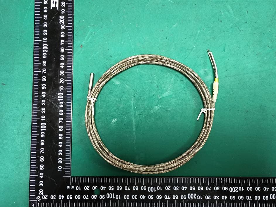
ZHZLTC2
Sep 16, 2024LoRaWAN IoT Sensor
Equipment Class
DTS - Digital Transmission System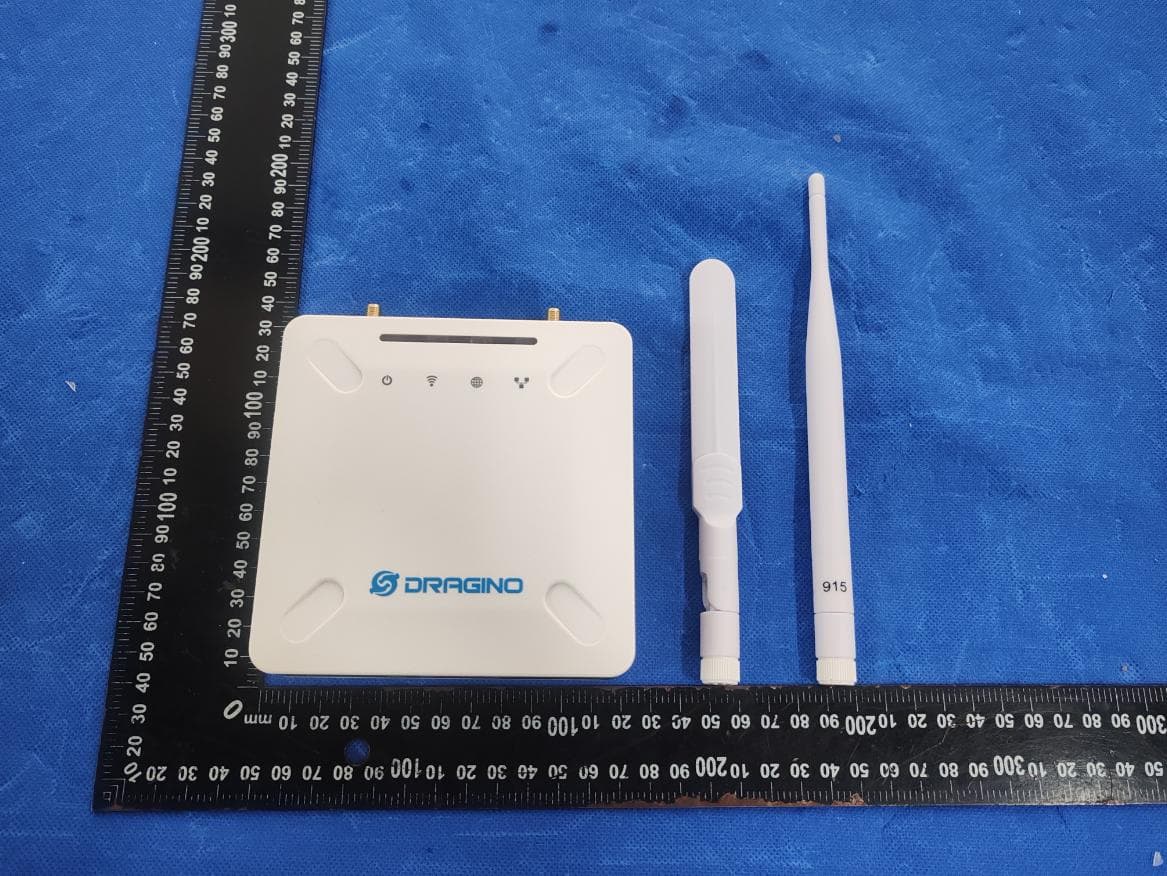
ZHZ-LPS8V2A
Jun 12, 2024LoRaWAN Gateway
Equipment Class
DTS - Digital Transmission System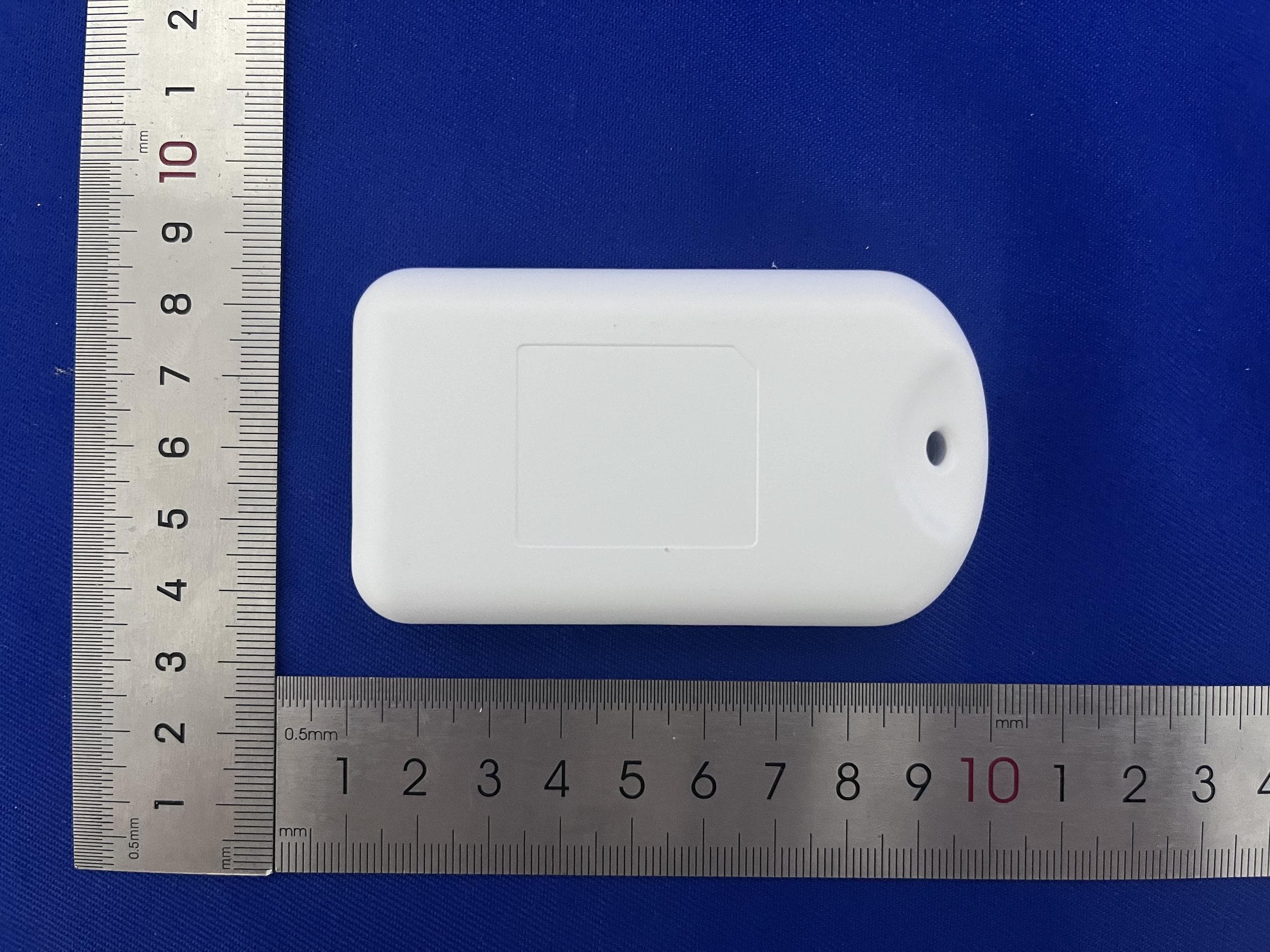
ZHZTRACD
Mar 12, 2024LoRaWAN Tracker
Equipment Class
DSS - Part 15 Spread Spectrum Transmitter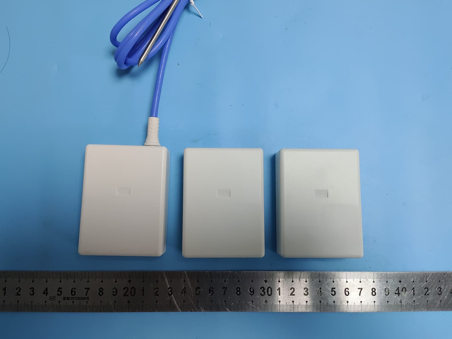
ZHZWTS
Nov 06, 2022WTS
Equipment Class
DSS - Part 15 Spread Spectrum Transmitter