ZHZHP0CLoRaWAN Indoor Gateway
Dragino Technology Co., Limited.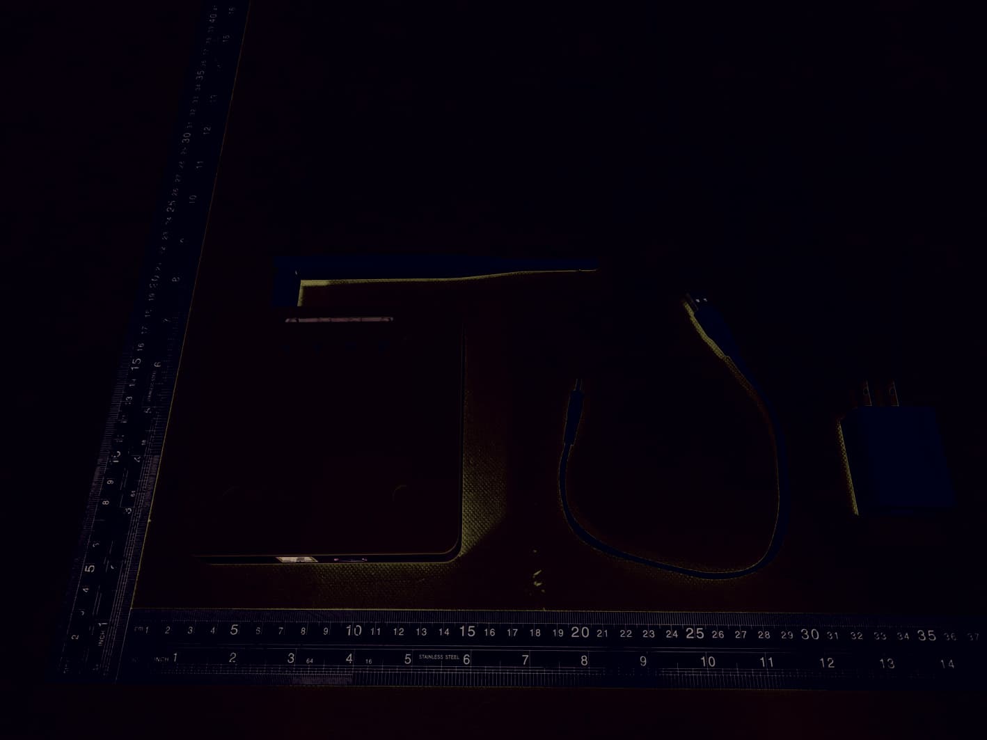
Click to zoom
Application Details
- Equipment Class
- DSS - Part 15 Spread Spectrum Transmitter
- Date of Grant
- Jun 01, 2022
- Application Purpose
- Original Equipment
- Date of Application
- Jun 01, 2022
- Equipment Note
- LoRaWAN Indoor Gateway
- Frequency Range
- 902.40000000 - 927.48000000
- Country
- China
Documents & Files
Document Text
Text extracted from the exhibit documents filed with the FCC. Open a document above to read the original.
Users Manual
www.dragino.com HP0C LoRaWAN Gateway User Manual 1 / 7 HP0D Full Hotspot for Helium User Manual Document Version: 0.1 Firmware Version: Version Description Date 0.1 Draft 2022-Feb-8 www.dragino.com HP0C LoRaWAN Gateway User Manual 2 / 7 Table of Contents 1 Introduction .............................................................................................................................. 3 1.1 What is HP0C .............................................................................................................................. 3 1.2 Specifications .............................................................................................................................. 3 1.3 Features ...................................................................................................................................... 3 1.4 Block Diagram ............................................................................................................................ 4 2 How to use ................................................................................................................................ 5 2.1 Get IP Address ............................................................................................................................ 5 2.2 SSH Access for Linux console ...................................................................................................... 5 2.3 Location of global_conf.json file. ................................................................................................ 5 2.4 Location of Semtech packet forwarder. ...................................................................................... 5 2.5 Start / stop pkt fwd .................................................................................................................... 5 2.6 Start Hopping script.................................................................................................................... 6 3 Manufacturer Info..................................................................................................................... 7 4 FCC Warning ............................................................................................................................. 7 www.dragino.com HP0C LoRaWAN Gateway User Manual 3 / 7 1 Introduction 1.1 What is HP0C The HP0C is a light hotspot for Helium. User can connect their sensors to Helium network via HP0C. 1.2 Specifications Hardware System: Linux Part: Orange Pi 4 Interface: 10M/100M RJ45 Ports x 1 LoRaWAN Wireless Operating Condition: Work Temperature: -20 ~ 65°C Storage Temperature: -20 ~ 65°C Power Input: 5V 2A, DC 1.3 Features Open Source Debian system Remote access with Reverse-SSH Emulates 49x LoRa demodulators LoRaWAN Gateway 10 programmable parallel demodulation paths Pre-configure to support different LoRaWAN regional settings. Allow to customize LoRaWAN regional parameters. Support Local decode ABP end node info and transfer to MQTT server Support different level log in. World Widely. Include US and EU www.dragino.com HP0C LoRaWAN Gateway User Manual 4 / 7 1.4 Block Diagram www.dragino.com HP0C LoRaWAN Gateway User Manual 5 / 7 2 How to use 2.1 Get IP Address Connect the HP0D Ethernet port to your router and HP0D will obtain an IP address from your router. In the router’s management portal, you should be able to find what IP address the router has assigned to the HP0D. You can use this IP to connect the WEB UI or SSH access of HP0D. 2.2 SSH Access for Linux console IP address: IP address of HP0C Port: 22 User Name: root Password: dragino (default) After logging in, you will be in the Linux console and can enter commands as shown below. 2.3 Location of global_conf.json file. /etc/lora/local_conf.json /etc/lora/global_conf.json 2.4 Location of Semtech packet forwarder. draginofwd --> /usr/bin/fwd_sx1302 2.5 Start / stop pkt fwd This is to stop/ start / restart the Semtech UDP packet forwarder: service draginofwd start service draginofwd stop service draginofwd restart www.dragino.com HP0C LoRaWAN Gateway User Manual 6 / 7 2.6 Start Hopping script systemctl stop draginofwd # Stop draginofwd ./Hopping_Script.sh #Start the hopping script Ctrl + c #Stop the Hopping script Modify the hopping script nano ./Hopping_Script.sh www.dragino.com HP0C LoRaWAN Gateway User Manual 7 / 7 3 Manufacturer Info Shenzhen Dragino Technology Development co. LTD Room 202, Block B, BCT Incubation Bases (BaoChengTai), No.8 CaiYunRoad LongCheng Street, LongGang District ; Shenzhen 518116,China 4 FCC Warning This device complies with part 15 of the FCC Rules. Operation is subject to the following two conditions: (1) This device may not cause harmful interference, and (2) this device must accept any interference received, including interference that may cause undesired operation. The users manual or instruction manual for an intentional or unintentional radiator shall caution the user that changes or modifications not expressly approved by the party responsible for compliance could void the user's authority to operate the equipment. In cases where the manual is provided only in a form other than paper, such as on a computer disk or over the Internet, the information required by this section may be included in the manual in that alternative form, provided the user can reasonably be expected to have the capability to access information in that form. This equipment has been tested and found to comply with the limits for a Class B digital device, pursuant to Part 15 of the FCC Rules. These limits are designed to provide reasonable protection against harmful interference in a residential installation. This equipment generates uses and can radiate radio frequency energy and, if not installed and used in accordance with the instructions, may cause harmful interference to radio communications. However, there is no guarantee that interference will not occur in a particular installation. If this equipment does ca…
Text truncated - open the document above for the full version.
Attestation Statements
Dragino Technology Co., Limited Model Difference Product description: LoRaWAN Indoor Gateway Model name:HP0C , LPS8v2 Trade Name: DRAGINO FCC ID:ZHZHP0C All the model are the same circuit and RF module, only for model name. Regards Sincerely Client’s signature: Client’s name / title : edwin chen (Manager) Contact information / address: Room 202, Block B, BCT Incubation Bases, No.8 CaiYunRoad LongCheng Street, LongGang District ; Shenzhen 518116,China
Cover Letter(s)
C5266091_X8_Ed.1 1/1 Letter of Authorization <Dragino Technology Co., Limited > Company:Dragino Technology Co., Limited Address:Room 202, Block B, BCT Incubation Bases, No.8 CaiYunRoad LongCheng Street, LongGang District ; Shenzhen 518116,China Product Name: LoRaWAN Indoor Gateway Model Number: HP0C , LPS8v2 FCC Identifier:ZHZHP0C We authorize LGAI Technological Center S.A., Ronda de la Font del Carme, s/n, 08193 Bellaterra, Spain, to act on our behalf on all matters concerning the above named equipment. Any individual within LGAI Technological Center S.A. is authorized to act on our behalf and take action on the application. We declare that authorize LGAI Technological Center S.A., Ronda de la Font del Carme, s/n, 08193 Bellaterra, Spain, is allowed to forward all information related to the approval project to the Federal Communication Commission and to discuss any issues concerning the approval application. Any and all acts carried out by LGAI Technological Center S.A. on our behalf shall have the same effect as acts of our own. Name: edwin chen Date: 2022-05-09 Title: Manager Signature of applicant:
Cover Letter(s)
C5266091_X10_Ed.1 1/1 < Dragino Technology Co., Limited > Office of Engineering Technology Federal Communications Commission 7435 Oakland Mills Road Columbia, MD 21046 Date: 2022-05-09 Subject: Request for Confidentiality FCC ID:ZHZHP0C To Whom It May Concern, Pursuant to the provisions of Sections 0.457 and 0.459 of Commission's rules (47CFR0.457, 0.459), we are requesting the Commission to withhold the following attachment(s) as confidential document from public disclosure. Exhibits Long-Term Confidentiality Short-Term Confidentiality ID Label/Location No No Attestation Statement No No External Photos No Block Diagram Schematics Test Report No No Test Setup Photos No User’s Manual Internal Photos Parts List / Tune Up RF Exposure Info Operational Description Cover Letter(s) No No SDR Software / Security Info No Above mentioned document contains detailed system and equipment description are considered as proprietary information in operation of the equipment. The public disclosure of above documents might be harmful to our company and would give competitor an unfair advantage in the market. It is our understanding that all measurement test reports, FCC ID label format and correspondent during certification review process cannot be granted as confidential documents and those information will be available for public review once the grant of equipment authorization is issued. Sincerely, Signature: Name: edwin chen Title: Manager
External Photos
EUT PHOTO(External Photos)
ID Label/Location Info
Labelandlabellocation LoRaWANIndoorGateway FCCID:ZHZHP0C
Internal Photos
EUT PHOTO(Internal Photos) ANT ※※ ※※※ END OF REPORT ※※※※※
RF Exposure Info
FCC ID:ZHZHP0C RF Exposure Evaluation Limits The criteria listed in the following table shall be used to evaluate the environment impact of human exposure to radio frequency (RF) radiation as specified in 1.1307(b) Limits for Maximum Permissible Exposure (MPE) Frequency range (MHz) Electric field strength (V/m) Magnetic field strength (A/m) Power density (mW/cm 2 ) Averaging time (minutes) (A) Limits for Occupational/Controlled Exposures 0.3–3.0 614 1.63 *(100) 6 3.0–30 1842/f 4.89/f *(900/f 2 ) 6 30–300 61.4 0.163 1.0 6 300–1500 f/300 6 1500–100,000 5 6 (B) Limits for General Population/Uncontrolled Exposure 0.3–1.34 614 1.63 *(100) 30 1.34–30 824/f 2.19/f *(180/f 2 ) 30 30–300 27.5 0.073 0.2 30 300–1500 f/1500 30 1500–100,000 1.0 30 f = frequency in MHz Friis transmission formula: Pd = (Pout*G)/(4*pi*r 2 ) Where Pd = power density in mW/cm 2 , Pout = output power to antenna in mW; G = gain of antenna in linear scale, Pi = 3.1416; R = distance between observation point and center of the radiator in cm Pd id the limit of MPE, 1 mW/cm 2 . If we know the maximum gain of the antenna and the total power input to the antenna, through the calculation, we will know the distance r where the MPE limit is reached. Test Procedure Software provided by client enabled the EUT to transmit and receive data at lowest, middle and highest channel individually. Test Result of RF Exposure Evaluation Wireless function Output power to antenna (dBm) Antenna Gain(dBi) Output power to antenna (mW) Power Density at R=20cm (mW/cm 2 ) Limit (mW/cm 2 ) Result 125KHz Bandwidth 21.118 5 129.36 0.081380 0.602 PASS 250KHz Bandwidth 21.223 5 132.53 0.083372 0.602 PASS 500KHz Bandwidth 18.782 5 75.54 0.047525 0.602 PASS
Test Report
Project No.: ZKT-2203011240E Page 1 of 43 TEST REPORT FCC ID:ZHZHP0C Report Number................................ : ZKT-2203011240E Date of Test .................................................Mar. 01, 2022 to May 31, 2022 Date of issue ..................................... : May 31, 2022 Total number of pages ....................... 43 Test Result........................................ : PASS Testing Laboratory. ........................ : Shenzhen ZKT Technology Co., Ltd. Address ............................................ : 1/F, No. 101, Building B, No. 6, Tangwei Community Industrial Avenue, Fuhai Street, Bao'an District, Shenzhen, China Applicant's name .......................... : Dragino Technology Co., Limited Address ............................................ : Room 202, Block B, BCT Incubation Bases, No.8 CaiYunRoad LongCheng Street, LongGang District ; Shenzhen 518116,China Manufacturer's name .................... : Dragino Technology Co., Limited. Address ............................................ : Room 202, Block B, BCT Incubation Bases, No.8 CaiYunRoad LongCheng Street, LongGang District ; Shenzhen 518116,China Test specification: Standard ........................................... : FCC CFR Title 47 Part 15 Subpart C Section 15.247 Test procedure ................................. : / Non-standard test method ............... : N/A Test Report Form No. .................... : TRF-EL-110_V0 Test Report Form(s) Originator .... : ZKT Testing Master TRF .................................... : Dated: 2020-01-06 This device described above has been tested by ZKT, and the test results show that the equipment under test (EUT) is in compliance with the FCC requirements. And it is applicable only to the tested sample identified in the report. This report shall not be reproduced except in full, without the written approval of ZKT, this document may be altered or revised by ZKT, personal only, and shall be noted in the revision of the document. Product name ................................. : LoRaWAN Indoor Gateway Trademark ....................................... : DRAGINO Model/Type reference ....................... : HP0C , LPS8v2 Ratings .............................................. : Input: DC 5V From AC Adapter Project No.: ZKT-2203011240E Page 2 of 43 Testing procedure and testing location: Testing Laboratory ................................... : Shenzhen ZKT Technology Co., Ltd. Address ...................................................... : 1/F, No. 101, Building B, No. 6, Tangwei Community Industrial Avenue, Fuhai Street, Bao'an District, Shenzhen, China Jim Liu Tested by (name + signature) .................... : Tom Zou Reviewer (name + signature) ..................... : Lake Xie Approved (name + signature) ..................... : Project No.: ZKT-2203011240E Page 3 of 43 TABLE OF CONTENTS Page 1.VERSION ........................................................................................................................................................... 4 2. TEST SUMMARY ............................................................................................................................................. 5 2.1 TEST FACILITY .......................................................................................................................................... 6 2.2 MEASUREMENT UNCERTAINTY ............................................................................................................. 6 3. GENERAL INFORMATION .............................................................................................................................. 7 3.1 GENERAL DESCRIPTION OF EUT ................................................................................................................... 7 3.2 TEST MODE .................................................................................................................................................. 9 3.3 TEST SETUP CONFIGURATION ....................................................................................................................... 9 3.4 SUPPORT EQUIPMENT ................................................................................................................................... 9 3.5 TEST INSTRUMENTS LIST ............................................................................................................................. 10 4. EMC EMISSION TEST ................................................................................................................................... 11 4.1 CONDUCTED EMISSIONS ............................................................................................................................. 11 4.2 CONDUCTED PEAK OUTPUT POWER ............................................................................................................ 14 4.3 20DB EMISSION BANDWIDTH ....................................................................................................................... 17 4.4 CARRIER FREQUENCIES SEPARATION .......................................................................................................... 20 4.5 HOPPING CHANNEL NUMBER ....................................................................................................................... 23 4.6 DWELL TIME ............................................................................................................................................... 24 4.7 BAND EDGE ................................................................................................................................................ 28 4.8 SPURIOUS EMISSION ................................................................................................................................... 31 4.9 RADIATED EMISSION METHOD ..................................................................................................................... 34 5. ANTENNA REQUIREMENT ...........................…
Text truncated - open the document above for the full version.
Test Report
Project No.: ZKT-2203011240E Page 21 of 43 Test plot as follows: Modulation mode: 125KHz Bandwidth Lowest channel Middle channel Highest channel Project No.: ZKT-2203011240E Page 22 of 43 Test mode: 250KHz Bandwidth Lowest channel Middle channel Highest channel Project No.: ZKT-2203011240E Page 23 of 43 4.5 Hopping Channel Number Test Requirement: FCC Part15 C Section 15.247 (a)(1) Test Method: ANSI C63.10:2013 Receiver setup: RBW=100kHz, VBW=300kHz, Frequency range=2400MHz-2483.5MHz, Detector=Peak Limit: If the 20 dB bandwidth of the hopping channel is less than 250 kHz, the system shall use at least 50 hopping frequencies. If the 20 dB bandwidth of the hopping channel is 250 kHz or greater, the system shall use at least 25 hopping frequencies Test setup: Test Instruments: Refer to section 6.0 for details Test mode: Refer to section 5.2 for details Test results: Pass Measurement Data: Mode Hopping channel numbers Limit Result 125KHz Bandwidth 128 50 Pass 250KHz Bandwidth 77 25 Pass 125KHz 250KHz Project No.: ZKT-2203011240E Page 24 of 43 4.6 Dwell Time Test Requirement: FCC Part15 C Section 15.247 (a)(1) Test Method: ANSI C63.10:2013 Receiver setup: RBW=10kHz, VBW=30KHz, Span=0Hz, Detector=Peak Limit: 0.4 Second Test setup: Test Instruments: Refer to section 6.0 for details Test mode: Refer to section 5.2 for details Test results: Pass Project No.: ZKT-2203011240E Page 25 of 43 Measurement Data Mode Ton(ms) Tcycle(ms) Dwell time(ms) Limit(ms) Result 125KHz Bandwidth 0.560 2.360 90.169 400 Pass 250KHz Bandwidth 0.210 1.680 15.00 400 Pass Note: Transmit numbers= Continue TX Time/Tcycle Dwell time=Transmit numbers*Ton Project No.: ZKT-2203011240E Page 26 of 43 Test plot as follows: Test Mode: 125KHz Bandwidth Ton&Tcycle Continue TX Time Project No.: ZKT-2203011240E Page 27 of 43 Test Mode: 250KHz Bandwidth Ton&Tcycle Continue TX Time Project No.: ZKT-2203011240E Page 28 of 43 4.7 Band Edge Test Requirement: FCC Part15 C Section 15.247 (d) Test Method: ANSI C63.10:2013 Receiver setup: RBW=100kHz, VBW=300kHz, Detector=Peak Limit: In any 100 kHz bandwidth outside the frequency band in which the spread spectrum intentional radiator is operating, the radio frequency power that is produced by the intentional radiator shall be at least 20 dB below that in the 100 kHz bandwidth within the band that contains the highest level of the desired power, based on either an RF conducted or a radiated measurement. Test setup: Test Instruments: Refer to section 6.0 for details Test mode: Refer to section 5.2 for details Test results: Pass Project No.: ZKT-2203011240E Page 29 of 43 Test plot as follows: 125KHz Bandwidth: Test channel: Lowest channel No-hopping mode Hopping mode Test channel: Highest channel No-hopping mode Hopping mode Project No.: ZKT-2203011240E Page 30 of 43 250KHz Bandwidth: Test channel: Lowest channel No-hopping mode Hopping mode Test channel: Highest channel No-hopping mode Hopping mode Project No.: ZKT-2203011240E Page 31 of 43 4.8 Spurious Emission Conducted Emission Method Test Requirement: FCC Part15 C Section 15.247 (d) Test Method: ANSI C63.10:2013 Limit: In any 100 kHz bandwidth outside the frequency band in which the spread spectrum intentional radiator is operating, the radio frequency power that is produced by the intentional radiator shall be at least 20 dB below that in the 100 kHz bandwidth within the band that contains the highest level of the desired power, based on either an RF conducted or a radiated measurement. Test setup: Test Instruments: Refer to section 6.0 for details Test mode: Refer to section 5.2 for details Test results: Pass Project No.: ZKT-2203011240E Page 32 of 43 125KHz Bandwidth: Test channel: Lowest channel 30MHz~10GHz Test channel: Middle channel 30MHz~10GHz Test channel: Highest channel 30MHz~10GHz Project No.: ZKT-2203011240E Page 33 of 43 250KHz Bandwidth: Test channel: Lowest channel 30MHz~10GHz Test channel: Middle channel 30MHz~10GHz Test channel: Highest channel 30MHz~10GHz Project No.: ZKT-2203011240E Page 34 of 43 4.9 Radiated Emission Method Test Requirement: FCC Part15 C Section 15.209 Test Method: ANSI C63.10:2013 Test Frequency Range: 9kHz to 25GHz Test site: Measurement Distance: 3m Receiver setup: Frequency Detector RBW VBW Value 9KHz-150KHz Quasi-peak 200Hz 600Hz Quasi-peak 150KHz-30MHz Quasi-peak 9KHz 30KHz Quasi-peak 30MHz-1GHz Quasi-peak 120KHz 300KHz Quasi-peak Above 1GHz Peak 1MHz 3MHz Peak Peak 1MHz 10Hz Average Limit: Frequency Limit (uV/m) Value Measurement Distance 0.009MHz-0.490MHz 2400/F(KHz) QP 300m 0.490MHz-1.705MHz 24000/F(KHz) QP 30m 1.705MHz-30MHz 30 QP 30m 30MHz-88MHz 100 QP 3m 88MHz-216MHz 150 QP 216MHz-960MHz 200 QP 960MHz-1GHz 500 QP Above 1GHz 500 Average 5000 Peak Test setup: For radiated emissions from 9kHz to 30MHz Project No.: ZKT-2203011240E Page 35 of 43 For radiated emissions from 30MHz to1GHz For radiated emissions above 1GHz Test Procedure: 1. The EUT was placed on the top of a rotating table (0.8m for below 1G and 1.5m for above 1G) above the ground at a 3 meter camber. The table was rotated 360 degrees to determine the position of the highest radiation. 2. The EUT was set 3 meters away from the interference-receiving antenna, which was mounted on the top of a variable-height antenna tower. 3. The antenna height is varied from one meter to four meters above the ground to determine the maximum value of the field strength. Both horizontal and vertical polarizations of the antenna are set to make the measurement. 4. For each suspected emission, the EUT was arranged to its worst case and then the antenna was tuned to heights from 1 meter to 4 meters and the rota table was turned from 0 degrees to 360 degrees to find the maximum reading. 5. The test-receiver system was set to Peak Detect Function and Specified Bandwidth with Maximum Hold Mode. 6. If the emission level of the EUT in peak mode was 10dB lower than the limit specified, then testing could be stopped and the peak values of the EUT would be reported…
Text truncated - open the document above for the full version.
Test Setup Photos
EUTTESTPHOTO
Contact Information
Applicant
edwin chen(Manager)
Technical Contact
Non-Technical Contact
Shenzhen ZKT Technology Co., Ltd.Lake xie
[email protected]0086-400 000 9970
Test Firm
Shenzhen ZKT Technology Co., Ltd.Lake Xie
[email protected]0086-13620010775
Technical Specifications
| # | Rule Parts | Frequency Range | Power Output |
|---|---|---|---|
| 2 | 15C | 902.4 MHz - 927.48 MHz | 132.53 mW |
Other Applications from Dragino Technology Co., Limited.

ZHZSN50V3-CNG
Sep 17, 2024HELIX NODE
Equipment Class
DSS - Part 15 Spread Spectrum Transmitter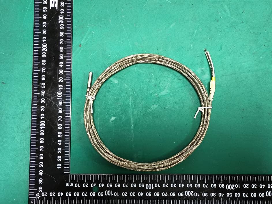
ZHZLTC2
Sep 16, 2024LoRaWAN IoT Sensor
Equipment Class
DTS - Digital Transmission System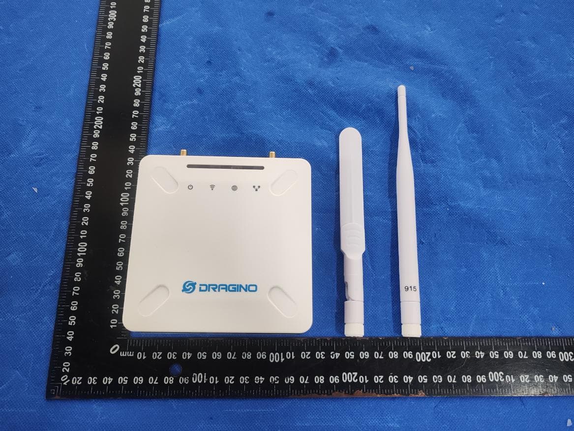
ZHZ-LPS8V2A
Jun 12, 2024LoRaWAN Gateway
Equipment Class
DTS - Digital Transmission System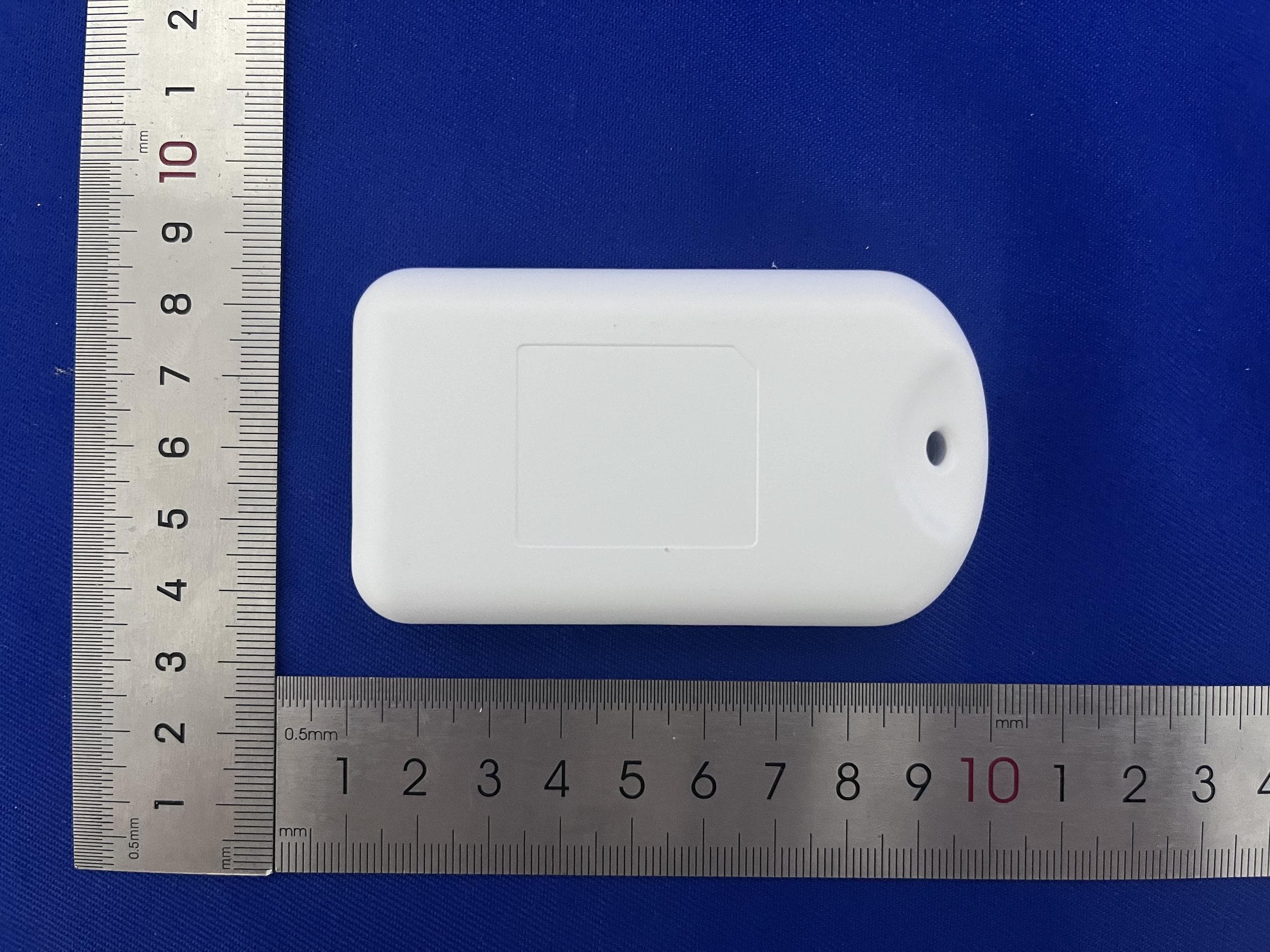
ZHZTRACD
Mar 12, 2024LoRaWAN Tracker
Equipment Class
DSS - Part 15 Spread Spectrum Transmitter
ZHZWTS
Nov 06, 2022WTS
Equipment Class
DSS - Part 15 Spread Spectrum Transmitter