ZHZLSN50V2LoRaWAN Sensor Node
Dragino Technology Co., Limited.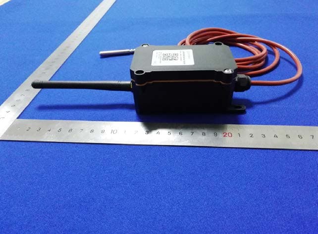
Click to zoom
Application Details
- Equipment Class
- DSS - Part 15 Spread Spectrum Transmitter
- Date of Grant
- Nov 30, 2020
- Application Purpose
- Original Equipment
- Date of Application
- Nov 29, 2020
- Equipment Note
- LoRaWAN Sensor Node
- Frequency Range
- 902.30000000 - 914.90000000
- Country
- China
Documents & Files
Document Text
Text extracted from the exhibit documents filed with the FCC. Open a document above to read the original.
Users Manual
www.dragino.com LSN50 LoRa Sensor Node User Manual 1 / 55 LSN50 LoRa Sensor Node User Manual Document Version: 1.6.4 Image Version: v1.6.3 Version Description Date 1.0 Release 2018-Dec-4 1.1 Add steps of install STM320x; Add ST-Link Upload firmware method 2018-Dec-27 1.2 Add trouble shooting for UART upload, Add change log for firmware v1.4 2019-Jan-23 1.2.1 More detail description for 8 channel mode and trouble shooting for using in US915/AU915 2019-Feb-21 1.2.2 Modify trouble shooting for upload via Flashloader 2019-Mar-13 1.2.3 Add ISP Mode / Flash mode different/ Add working flow diagram (Chapter 2.1 how it works) Add FAQ for how to configure the Keys 2019-Apr-1 1.5.0 Upgrade to v1.5 version firmware Add ultrasonic sensor support and description. Add downlink description Change decoder for v1.5 Add working flow chart Add Mydevices support 2019-Apr-19 1.5.1 Improve Interrupt feature, change interrupt example to use door sensor 1.5.2 Various minor text and format edits. 2019-Jun-10 1.6.0 Update to firmware v1.6 version, add 3ADC mode 2019-Aug-7 1.6.1 Trouble shooting for AT Command input Add support for 3 * DS18B20 (MOD4) 2019-Sep-18 1.6.2 Add door sensor detail/ power, Add battery connector info 2019-Dec-13 1.6.3 Add firmware version 1.6.2 change log, Add support for HX711 Weight Sensor 2019-Dec-31 1.6.4 Add New AT Command for 1.6.3. Add LSN50 v2.0 Hardware info. Add battery measure suggestion 2020-Apr-27 www.dragino.com LSN50 LoRa Sensor Node User Manual 2 / 55 1. Introduction 4 1.1 What is LSN50 LoRa Sensor Node 4 1.2 Specifications 5 1.3 Features 6 1.4 Applications 6 1.5 Pin Definitions 7 1.6 Hardware Change log 8 1.7 Hole Option 10 2. Use LSN50 with LoRaWAN firmware 11 2.1 How it works 11 2.2 Quick guide to connect to LoRaWAN server (OTAA) 12 2.3 Working Mode & Uplink Payload 15 2.3.1 MOD=1 (Default Mode) 15 2.3.2 MOD=2 (Distance Mode) 16 2.3.3 MOD=3 (3 ADC + I2C) 17 2.3.4 MOD=4 (3 x DS18B20) 18 2.3.5 MOD=5(Weight Measurement by HX711) 19 2.3.6 Decode payload in The Things Network 20 2.4 Payload Explanation and Sensor Interface 21 2.4.1 Battery Info 21 2.4.2 Temperature (DS18B20) 21 2.4.3 Digital Input 21 2.4.4 Analogue Digital Converter (ADC) 22 2.4.5 Digital Interrupt 23 2.4.6 I2C Interface (SHT20) 25 2.4.7 Distance Reading 26 2.4.8 Ultrasonic Sensor 26 2.4.9 +5V Output 27 2.4.10 Weigh Sensor HX711 27 2.5 Downlink Payload 29 2.6 Show Data in Mydevices IoT Server 30 2.7 Firmware Change Log 33 2.8 Battery Analysis 35 2.8.1 Battery Type 35 2.8.2 Power consumption Analyze 35 2.8.3 Battery Note 37 2.8.4 Replace the battery 37 3. Using the AT Commands 37 3.1 Access AT Commands 37 3.2 Common AT Command Sequence 40 3.2.1 Multi-channel ABP mode (Use with SX1301/LG308) 40 3.2.2 Single-channel ABP mode (Use with LG01/LG02) 40 4. Upload Firmware 41 4.1 Upload Firmware via Serial Port 41 4.2 Upload Firmware via ST-Link V2 44 5. Developer Guide 46 www.dragino.com LSN50 LoRa Sensor Node User Manual3 / 55 6.FAQ48 6.1 Why there is 433/868/915 version? 48 6.2 What is the frequency range of LT LoRa part? 48 6.3 How to change the LoRa Frequency Bands/Region? 48 6.4 Can I use Private LoRa protocol? 48 6.5 How to set up LSN50 to work with Single Channel Gateway such as LG01/LG02? 49 6.6 How to configure the EUI keys in LSN50? 51 7. Trouble Shooting52 7.1 Connection problem when uploading firmware. 52 7.2 Why I can’t join TTN in US915 / AU915 bands? 52 7.3 AT Command input doesn’t work 53 8. Order Info54 9.Packing Info54 10.Support55 11. References55 www.dragino.com LSN50 LoRa Sensor Node User Manual 4 / 55 1. Introduction 1.1 What is LSN50 LoRa Sensor Node LSN50 is a Long Range LoRaWAN Sensor Node. It is designed for outdoor data logging and powered by Li/SOCl2 battery for long term use and secure data transmission. It is designed to facilitate developers to quickly deploy industrial level LoRa and IoT solutions. It helps users to turn the idea into a practical application and make the Internet of Things a reality. It is easy to program, create and connect your things everywhere. It is based on SX1276/SX1278 allows the user to send data and reach extremely long ranges at low data-rates. It provides ultra-long range spread spectrum communication and high interference immunity whilst minimizing current consumption. It targets professional wireless sensor network applications such as irrigation systems, smart metering, smart cities, smartphone detection, building automation, and so on. LSN50 uses STM32l0x chip from ST, STML0x is the ultra-low-power STM32L072xx microcontrollers incorporate the connectivity power of the universal serial bus (USB 2.0 crystal-less) with the high-performance ARM® Cortex®-M0+ 32-bit RISC core operating at a 32 MHz frequency, a memory protection unit (MPU), high-speed embedded memories (192 Kbytes of Flash program memory, 6 Kbytes of data EEPROM and 20 Kbytes of RAM) plus an extensive range of enhanced I/Os and peripherals. LSN50 is an open source product, it is based on the STM32Cube HAL drivers and lots of libraries can be found in ST site for rapid development. www.dragino.com LSN50 LoRa Sensor Node User Manual5 / 55 1.2 Specifications Micro Controller: ●STM32L072CZT6 MCU ●MCU: STM32L072CZT6 ●Flash: 192KB ●RAM: 20KB ●EEPROM: 6KB ●Clock Speed: 32Mhz Common DC Characteristics: ●Supply Voltage: 2.1v ~ 3.6v ●Operating Temperature: -40 ~ 85°C ●I/O pins: Refer to STM32L072 datasheet LoRa Spec: ●Frequency Range, ○Band 1 (HF): 902 ~ 928Mhz ●Programmable bit rate up to 300 kbps. ●High sensitivity: down to -148 dBm. ●Bullet-proof front end: IIP3 = -12.5 dBm. ●Excellent blocking immunity. ●Low RX current of 10.3 mA, 200 nA register retention. ●Fully integrated synthesizer with a resolution of 61 Hz. ●FSK modulation. ●Built-in bit synchronizer for clock recovery. ●Preamble detection. ●127 dB Dynamic Range RSSI. ●Automatic RF Sense and CAD with ultra-fast AFC. ●Packet engine up to 256 bytes with CRC. ●LoRaWAN 1.0.2 Specification Battery: ●Li/SOCI2 un-chargeable battery ●Capacity: 4000mA…
Text truncated - open the document above for the full version.
Cover Letter(s)
DATA :11/25/2020 Equipment Autorisation Division Federal Communications Commission 7435 Oakland Mills Road Columbia, MD 21046 FCC ID: ZHZLSN50V2 Product Name: LoRaWAN Sensor Node Request for Confidentiality Pursuant to Sections 0.457 and 0.459 of the commission’s rules, we hereby request that the following documents be held confidential: (List here the documents for which you are seeking confidentiality – for example ...) • Schematics • Block diagram • Operation description These materials contain trade secrets and proprietary information and are not customarily released to the public. The public disclosure of this information might be harmful to the company and provide unjustified benefits to our competitors. <Signature> Name: edwin chen Title: General manager Company: Dragino Technology Co., Limited.
Cover Letter(s)
DATA :11/25/2020 Federal Communications Commission Authorization & Evaluation Division 7345 Oakland Mills Road Columbia, Maryland 21046 Authority to Act as Agent On our behalf, I appoint Global United Technology Services Co., Ltd. Address: No. 123- 128, Tower A, Jinyuan Business Building, No.2, Laodong Industrial Zone, Xixiang Road, Baoan District, Shenzhen, Guangdong, China 518102 (Name of Agent company name and address) to act as our agent in the preparation of this application for equipment certification. I certify that submitted documents properly describe the device or system for which equipment certification is sought. I also certify that each unit manufactured, imported or marketed, as defined in the Federal Communications Commission’s regulations will have affixed to it a label identical to that submitted for approval with this application. For instances where our authorized agent signs the application for certification on our behalf, I acknowledge that all responsibility for complying with the terms and conditions for certification, still resides with Dragino Technology Co., Limited. Address: Room 202,BaoChengTai industrial park,No.8 CaiYun LongCheng Street,LongGang District, Shenzhen 518116, China (Applicant Name and address) <Signature> Name: edwin chen Title: General manager Applicant Company: Dragino Technology Co., Limited.
External Photos
GTS202010000087 Product Name: LoRaWAN Sensor Node Test Model No.: LSN50v2 External Photos Global United Technology Services Co., Ltd. No. 123-128, Tower A, Jinyuan Business Building, No.2, Laodong Industrial Zone, Xixiang Road, Baoan District, Shenzhen, Guangdong, China 518102 Telephone: +86 (0) 755 2779 8480 Fax: +86 (0) 755 2779 8960 Page 1 of 3 GTS202010000087 Global United Technology Services Co., Ltd. No. 123-128, Tower A, Jinyuan Business Building, No.2, Laodong Industrial Zone, Xixiang Road, Baoan District, Shenzhen, Guangdong, China 518102 Telephone: +86 (0) 755 2779 8480 Fax: +86 (0) 755 2779 8960 Page 2 of 3 GTS202010000087 RF Antenna Global United Technology Services Co., Ltd. No. 123-128, Tower A, Jinyuan Business Building, No.2, Laodong Industrial Zone, Xixiang Road, Baoan District, Shenzhen, Guangdong, China 518102 Telephone: +86 (0) 755 2779 8480 Fax: +86 (0) 755 2779 8960 Page 3 of 3
ID Label/Location Info
Label&Label location 30mmX38mm
Internal Photos
GTS202010000087 Product Name: LoRaWAN Sensor Node Test Model No.: LSN50v2 Internal Photos Global United Technology Services Co., Ltd. No. 123-128, Tower A, Jinyuan Business Building, No.2, Laodong Industrial Zone, Xixiang Road, Baoan District, Shenzhen, Guangdong, China 518102 Telephone: +86 (0) 755 2779 8480 Fax: +86 (0) 755 2779 8960 Page 1 of 3 GTS202010000087 Global United Technology Services Co., Ltd. No. 123-128, Tower A, Jinyuan Business Building, No.2, Laodong Industrial Zone, Xixiang Road, Baoan District, Shenzhen, Guangdong, China 518102 Telephone: +86 (0) 755 2779 8480 Fax: +86 (0) 755 2779 8960 Page 2 of 3 GTS202010000087 ------End------ Global United Technology Services Co., Ltd. No. 123-128, Tower A, Jinyuan Business Building, No.2, Laodong Industrial Zone, Xixiang Road, Baoan District, Shenzhen, Guangdong, China 518102 Telephone: +86 (0) 755 2779 8480 Fax: +86 (0) 755 2779 8960 Page 3 of 3
RF Exposure Info
FCC ID: ZHZLSN50V2 RF Exposure Evaluation Limits The criteria listed in the following table shall be used to evaluate the environment impact of human exposure to radio frequency (RF) radiation as specified in 1.1307(b) Limits for Maximum Permissible Exposure (MPE) Frequency range (MHz) Electric field strength (V/m) Magnetic field strength (A/m) Power density (mW/cm 2 ) Averaging time (minutes) (A) Limits for Occupational/Controlled Exposures 0.3–3.0 614 1.63 *(100) 6 3.0–30 1842/f 4.89/f *(900/f 2 ) 6 30–300 61.4 0.163 1.0 6 300–1500 f/300 6 1500–100,000 5 6 (B) Limits for General Population/Uncontrolled Exposure 0.3–1.34 614 1.63 *(100) 30 1.34–30 824/f 2.19/f *(180/f 2 ) 30 30–300 27.5 0.073 0.2 30 300–1500 f/1500 30 1500–100,000 1.0 30 f = frequency in MHz Friis transmission formula: Pd = (Pout*G)/(4*pi*r 2 ) Where Pd = power density in mW/cm 2 , Pout = output power to antenna in mW; G = gain of antenna in linear scale, Pi = 3.1416; R = distance between observation point and center of the radiator in cm Pd id the limit of MPE, 1 mW/cm 2 . If we know the maximum gain of the antenna and the total power input to the antenna, through the calculation, we will know the distance r where the MPE limit is reached. Test Procedure Software provided by client enabled the EUT to transmit and receive data at lowest, middle and highest channel individually. Test Result of RF Exposure Evaluation Wireless function Output power to antenna (dBm) Antenna Gain(dBi) Output power to antenna (mW) Power Density at R=20cm (mW/cm 2 ) Limit (mW/cm 2 ) Result 125KHz Bandwidth 17.487 2.00 56.066 0.01768 0.602 PASS 500KHz Bandwidth 14.039 2.00 25.345 0.00799 0.602 PASS
Test Report
Global United Technology Services Co., Ltd. Report No.: GTS202010000087F01 1 Cover Page TEST REPORT Applicant: Dragino Technology Co., Limited. Address of Applicant: Room 202,BaoChengTai industrial park,No.8 CaiYun LongCheng Street,LongGang District, Shenzhen 518116, China Manufacturer/Factory : Dragino Technology Co., Limited. Address of Manufacturer/Factory : Room 202,BaoChengTai industrial park,No.8 CaiYun LongCheng Street,LongGang District, Shenzhen 518116, China Equipment Under Test (EUT) Product Name: LoRaWAN Sensor Node Model No.: LSN50v2 Trade Mark: Dragino FCC ID: ZHZLSN50V2 Applicable standards: FCC CFR Title 47 Part 15 Subpart C Section 15.247 Date of sample receipt: Oct. 12, 2020 Date of Test: Oct. 12 – Nov. 05, 2020 Date of report issued: Nov. 05, 2020 Test Result : PASS * * In the configuration tested, the EUT complied with the standards specified above. Authorized Signature: Robinson Lo Laboratory Manager This results shown in this test report refer only to the sample(s) tested, this test report cannot be reproduced, except in full, without prior written permission of the company. The report would be invalid without specific stamp of test institute and the signatures of compiler and approver. Page 1 of 57 Report No.: GTS202010000087F01 2 Version Version No. Date Description 00 Nov. 05, 2020 Original Prepared By: Date: Nov. 05, 2020 Project Engineer Check By: Date: Nov. 05, 2020 Reviewer Global United Technology Services Co., Ltd. No. 123-128, Tower A, Jinyuan Business Building, No.2, Laodong Industrial Zone, Xixiang Road, Baoan District, Shenzhen, Guangdong, China 518102 Telephone: +86 (0) 755 2779 8480 Fax: +86 (0) 755 2779 8960 Page 2 of 57 Report No.: GTS202010000087F01 3 Contents Page 1 COVER PAGE .................................................................................................................................... 1 2 VERSION ............................................................................................................................................ 2 3 CONTENTS ........................................................................................................................................ 3 4 TEST SUMMARY ............................................................................................................................... 5 5 GENERAL INFORMATION ................................................................................................................. 6 5.1 GENERAL DESCRIPTION OF EUT ..................................................................................................... 6 5.2 TEST MODE ................................................................................................................................... 8 5.3 DESCRIPTION OF SUPPORT UNITS ................................................................................................... 8 5.4 DEVIATION FROM STANDARDS ......................................................................................................... 8 5.5 ABNORMALITIES FROM STANDARD CONDITIONS ................................................................................ 8 5.6 TEST FACILITY .............................................................................................................................. 8 5.7 TEST LOCATION ............................................................................................................................ 8 6 TEST INSTRUMENTS LIST ............................................................................................................... 9 7 TEST RESULTS AND MEASUREMENT DATA .................................................................................11 7.1 ANTENNA REQUIREMENT ...............................................................................................................11 7.2 CONDUCTED EMISSIONS ...............................................................................................................12 8 TEST ITEMS FOR HYBRID ...............................................................................................................13 8.1 CONDUCTED PEAK OUTPUT POW ER ...............................................................................................13 8.2 20DB EMISSION BANDWIDTH .........................................................................................................15 8.3 CARRIER FREQUENCIES SEPARATION .............................................................................................17 8.4 HOPPING CHANNEL NUMBER .........................................................................................................19 8.5 DW ELL TIME ................................................................................................................................20 8.6 PSEUDORANDOM FREQUENCY HOPPING SEQUENCE.........................................................................22 8.7 BAND EDGE .................................................................................................................................23 8.7.1 Conducted Emission Method ..................................................................................................23 8.7.2 Radiated Emission Method.....................................................................................................25 8.8 SPURIOUS EMISSION .....................................................................................................................27 8.8.1 Conducted Emission Method ..................................................................................................27 8.8.2 Radiated Emission Method.....................................................................................................29 9 TEST ITEMS FOR DTS .....................................................................................................................37 9.1 CONDUCTED PEAK OUTPUT POW ER .............................................................................................…
Text truncated - open the document above for the full version.
Test Setup Photos
GTS202010000087 Global United Technology Services Co., Ltd. No. 123-128, Tower A, Jinyuan Business Building, No.2, Laodong Industrial Zone, Xixiang Road, Baoan District, Shenzhen, Guangdong, China 518102 Telephone: +86 (0) 755 2779 8480 Fax: +86 (0) 755 2779 8960 Page 1 of 1 Product Name: LoRaWAN Sensor Node Test Model No.: LSN50v2 TestSetup photo Radiated Emission ------End------
Contact Information
Applicant
edwin chen(Manager)
Test Firm
Global United Technology Services Co. Ltd.Robinson Lo
Technical Specifications
| # | Rule Parts | Frequency Range | Power Output |
|---|---|---|---|
| 1 | 15C | 902.3 MHz - 914.9 MHz | 56.07 mW |
Other Applications from Dragino Technology Co., Limited.

ZHZSN50V3-CNG
Sep 17, 2024HELIX NODE
Equipment Class
DSS - Part 15 Spread Spectrum Transmitter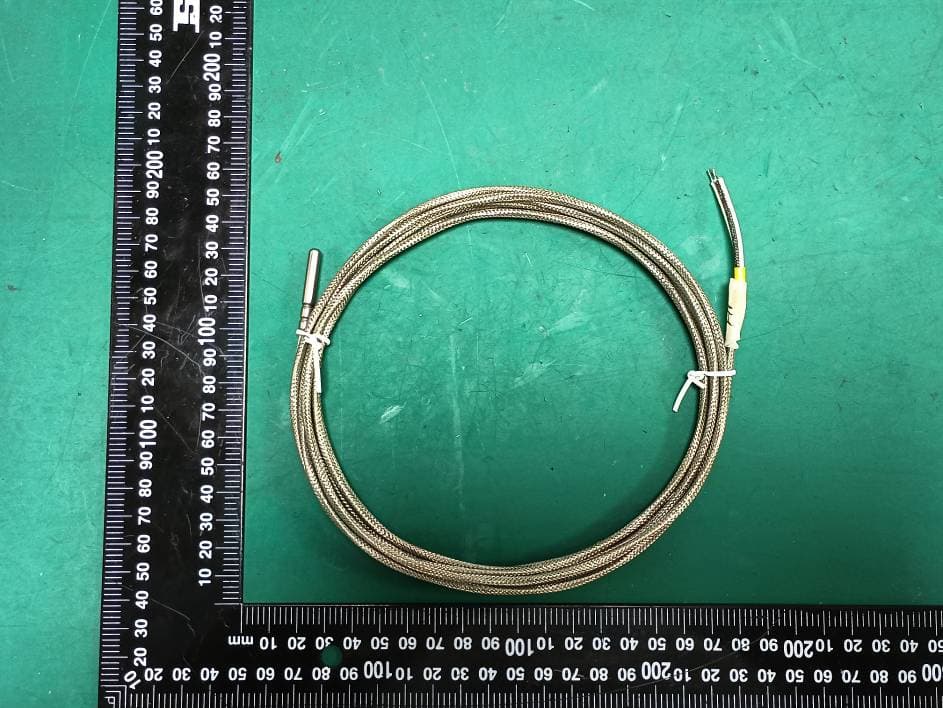
ZHZLTC2
Sep 16, 2024LoRaWAN IoT Sensor
Equipment Class
DTS - Digital Transmission System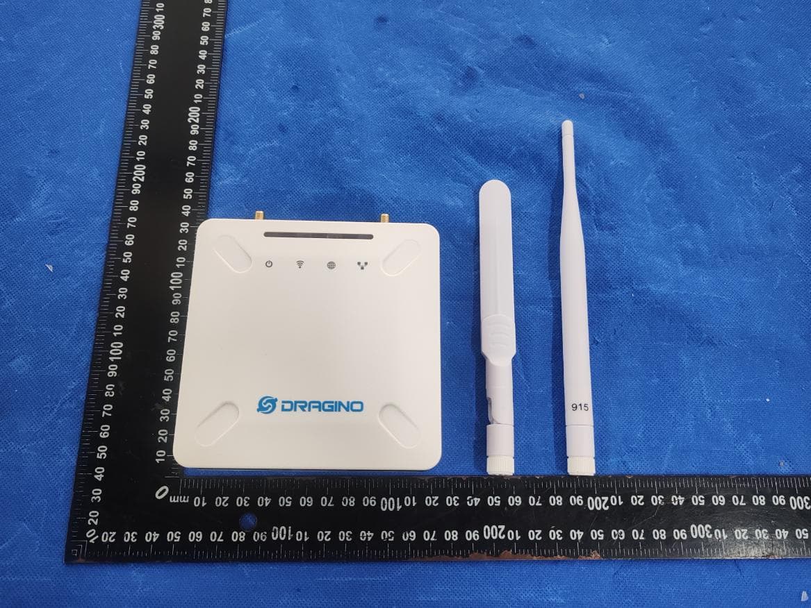
ZHZ-LPS8V2A
Jun 12, 2024LoRaWAN Gateway
Equipment Class
DTS - Digital Transmission System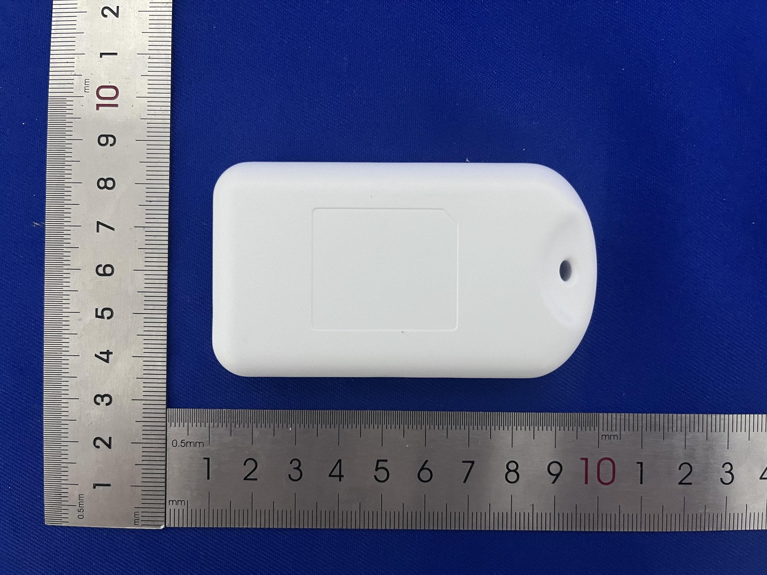
ZHZTRACD
Mar 12, 2024LoRaWAN Tracker
Equipment Class
DSS - Part 15 Spread Spectrum Transmitter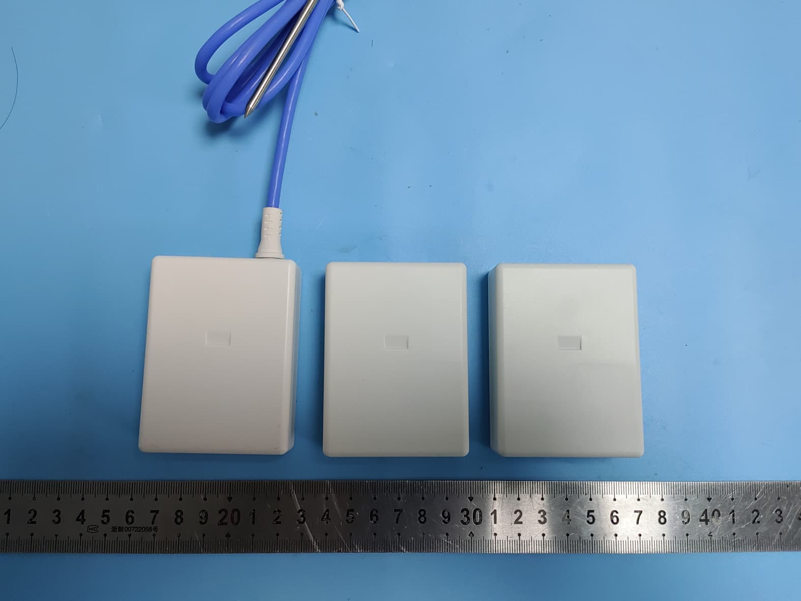
ZHZWTS
Nov 06, 2022WTS
Equipment Class
DSS - Part 15 Spread Spectrum Transmitter