ZHZMS14Wireless Sensor Node
Dragino Technology Co., Limited.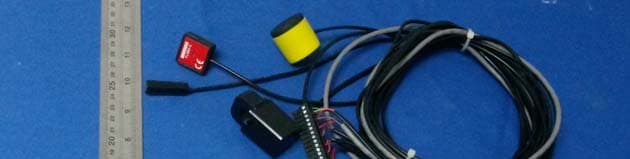
Click to zoom
Application Details
- Equipment Class
- DXX - Part 15 Low Power Communication Device Transmitter
- Date of Grant
- Dec 23, 2013
- Application Purpose
- Original Equipment
- Date of Application
- Dec 23, 2013
- Equipment Note
- Wireless Sensor Node
- Frequency Range
- 915.00000000 - 915.00000000
- Country
- China
Documents & Files
Document Text
Text extracted from the exhibit documents filed with the FCC. Open a document above to read the original.
Users Manual
Contents Prefacev 1 Introduction1 1.1 Ports . . . . . . . . . . . . . . . . . . . . . . . . . . . . . . . . . .1 1.1.1Screw Terminal . . . . . . . . . . . . . . . . . . . . . . . .1 1.1.2Ethernet . . . . . . . . . . . . . . . . . . . . . . . . . . . .1 1.1.3Power Jack . . . . . . . . . . . . . . . . . . . . . . . . . .1 1.2 Pushbutton . . . . . . . . . . . . . . . . . . . . . . . . . . . . . .2 1.3 LEDs . . . . . . . . . . . . . . . . . . . . . . . . . . . . . . . . .2 2 Deploying5 2.1 Networking . . . . . . . . . . . . . . . . . . . . . . . . . . . . . .5 2.1.1Wifi Mode . . . . . . . . . . . . . . . . . . . . . . . . . . .5 2.1.2Ethernet Mode . . . . . . . . . . . . . . . . . . . . . . . .5 2.2 Configuring Sensors . . . . . . . . . . . . . . . . . . . . . . . . .6 2.2.1Status . . . . . . . . . . . . . . . . . . . . . . . . . . . . .6 2.2.2Services . . . . . . . . . . . . . . . . . . . . . . . . . . . .7 2.2.3Current Clamp Setup . . . . . . . . . . . . . . . . . . . .7 2.2.4Sensors . . . . . . . . . . . . . . . . . . . . . . . . . . . .7 2.3 Securing the Fluksometer . . . . . . . . . . . . . . . . . . . . . .8 2.4 Attaching Current Clamps . . . . . . . . . . . . . . . . . . . . . .8 2.5 Connecting Sensor Clamp Cables . . . . . . . . . . . . . . . . . .8 2.6 Powering Up . . . . . . . . . . . . . . . . . . . . . . . . . . . . .8 2.7 Registering . . . . . . . . . . . . . . . . . . . . . . . . . . . . . .9 2.8 Congratulations . . . . . . . . . . . . . . . . . . . . . . . . . . . .9 3 Accessing11 3.1 Version . . . . . . . . . . . . . . . . . . . . . . . . . . . . . . . . 11 3.2 Token . . . . . . . . . . . . . . . . . . . . . . . . . . . . . . . . . 11 3.3 Data Types . . . . . . . . . . . . . . . . . . . . . . . . . . . . . . 12 3.4 Retrieving sensor time series data . . . . . . . . . . . . . . . . . . 12 3.5 Retrieving sensor parameters . . . . . . . . . . . . . . . . . . . . 14 3.6 Retrieving real-time sensor data . . . . . . . . . . . . . . . . . . . 14 iii Preface This version of the Fluksometer Manual is based on commit d0f7b63c7cb48826 of the Flukso Git repository. v Chapter 1 Introduction Let’s kick off this manual with a short tour of a Fluksometer’s externals. We will introduce each of the Fluksometer’s ports, buttons and LEDs. 1.1 Ports 1.1.1 Screw Terminal The screw terminal contains twelve inputs. Aporton the screw terminal is defined as apair of adjacent inputs. We have printed the port numbers on the side of the enclosure for easy reference, with the polarity denoted by + and -. Ports 1 to 3 are analog ports that are tuned to accept Flukso split-core current clamps. Ports 4 and 5 can be used for detecting pulses. This includes support for, but is not limited to, the S0 interface 1 common to DIN-rail energy meters. Finally, port 6 offers a half-duplex RS-485 serial interface. Contrary to the other ports, the RS-485 port has its polarity indicated by the letters a and b. 1.1.2 Ethernet The ethernet port offers support for a 10baseT/100baseTx interface with auto- negotiation and auto MDI/MDI-X crossover detection. 1.1.3 Power Jack The center-positive power jack accepts a DC voltage between 9V and 15V. The switching adapter should have a minimum rating of 500mA output current. 1 S0 is an open-collector interface standardized in DIN EN 62053-31 1 2CHAPTER 1. INTRODUCTION 1.2 Pushbutton The pushbutton has a triple function. Which function will be triggered depends on how long the button is pressed. Make sure the heartbeat LED is blinking before using the button. Toggle reporting modeIf you press the button for 2 to 5 seconds, the Fluk- someter will toggle its reporting mode to the Flukso server from wifi to ethernet or vice-versa. A blinking wifi LED indicates the Fluksometer is in wifi mode. An always-off wifi LED means it’s in ethernet mode 2 . Restore networking defaultsIf you press the button between 10 and 30 seconds, the Fluksometer will restore its default network settings. Restore firmwareKeep the button pressed for between 60 and 120 seconds to restore the Fluksometer’s stock firmware 3 and reboot. You will have to reconfigure all network and sensor settings. Connect to the local web interface after the heartbeat LED starts blinking again. 1.3 LEDs The Fluksometer has five red LEDs on the top of its enclosure. Together these LEDs provide us with an overview of the Fluksometer’s internal functioning, the status of its network interfaces and its ability to communicate with the Flukso server. From left to right, these LEDs are: WifiIf the wifi interface is enabled, the wifi LED will blink. A fast blink rate [approx. twice per second] signals that no wifi connection can be established. A slow blink rate [once every three seconds] signifies that a wifi connection has been successfully set up. EthernetThe ethernet LED will be on when an ethernet link is established. This can either be a 10baseT or 100baseTX link in full- or half-duplex mode. GlobeAfter the Fluksometer has finished its boot sequence, the globe LED will be on when it can access the Flukso server. Every time the Fluksometer reports to the Flukso server, the LED will blink in case of a successful call. The globe LED will be turned off when the call is not completed successfully. A successful call has been made when either a 200 or 204 HTTP response code is returned by the Flukso server. HeartbeatThe heartbeat LED is positioned right next to the globe led. While the globe LED informs us about the status of the Fluksometer’s external communication, the heartbeat LED allows us to monitor the Fluksome- ter’s internal functioning. This LED will be on when the sensor board is running its firmware. From the moment the Flukso daemon is started during the boot sequence, it will start polling the sensor board every sec- 2 prior to r221 the wifi led would be always on after toggling to ethernet mode 3 supported from r216 onwards 1.3. LEDS3 ond for data. Each poll triggers a blink of this LED, thus mimicking a real heartbeat. Hence…
Text truncated - open the document above for the full version.
Cover Letter(s)
Dragino Technology Co., Limited. Room 2073, Zi'An Commercial Building, Qian Jin 1 Road. Xin'An 6th District, Bao'an District ; Shenzhen 518101,China FCC ID: ZHZMS14 To Whom It May Concern: We, the undersigned, hereby attest to the fact that we will apply the Declaration of Conformity procedure to the class B computer peripheral portion of this composite device. We understand that devices subject to the DoC procedure are required to be tested to show compliance with the FCC technical regulations by a recognized accredited testing laboratory. The testing laboratory must be accredited by a Commission approved accreditation body or designated under the terms of a government-to-government Mutual Recognition Agreement (MRA). A listing of those accredited testing laboratories that have been recognized by the Commission is published on the FCC Test facilities located in countries, where the U.S. does not have an operational Telcom MRA are not recognized by the FCC to test for the DoC procedure. Sincerely, Signature: name / title : Edwin chen information / address: Dragino Technology Co., Limited. (Room 2073, Zi'An Commercial Building, Qian Jin 1 Road. Xin'An 6th District, Bao'an District ; Shenzhen 518101,China ) FCC DOC approval will be got before the product to sell. are applying
Cover Letter(s)
Updated on 2005/02/07 by Kally Chan DECLARATION OF IDENTITY FCC ID: ZHZMS14 Hereby we: Dragino Technology Co., Limited. (Name of Manufacturer) Basic Model Number: Wireless Sensor Node Basic Brand Name: MS14 Basic Product Name: DRAGINO Declare the Circuit, PCB Layout, shape of enclosure and Electrical Parts of the following product(s) are identical to the basic model: New / Additional Model Number(s): FLM03B, MS14-P, MS14-S, MS14-MLC New / Additional Brand Name(s): FLUKSO Except the following(s) : Model numbers,outlook color Signature with Company Chop : Printed Name : Edwin chen DATE:2013-11-27
Cover Letter(s)
Dragino Technology Co., Limited. Room 2073, Zi'An Commercial Building, Qian Jin 1 Road. Xin'An 6th District, Bao'an District ; Shenzhen 518101,China DATE:2013-11-27 Equipment Autorisation Division Federal Communications Commission 7435 Oakland Mills Road Columbia, MD 21046 FCC ID: ZHZMS14 Product Name: Wireless Sensor Node Request for Confidentiality Pursuant to Sections 0.457 and 0.459 of the commissions rules, we hereby request that the following documents be held confidential: • Schematics • Block diagram • Operation description These materials contain trade secrets and proprietary information and are not customarily released to the public. The public disclosure of this information might be harmful to the company and provide unjustified benefits to our competitors. Dated this Day of 11/27/2012 By: Edwin chen Signature Printed Title: Manager On behalf of : Dragino Technology Co., Limited. Telephone: +86-755-86610821
ID Label/Location Info
Label location
Internal Photos
WIFI Antenna 915M Antenna
Test Report
FCC ID: ZHZMS14 Keyway Testing Technology Co., Ltd. Report No. 13KWE11103808R Page 1 of 22 FCC TEST REPORT for DRAGINO TECHNOLOGY CO., LIMITED Wireless Sensor Node Model Number: MS14, FLM03B, MS14-P, MS14-S, MS14-MLC FCC ID: ZHZMS14 Prepared for : DRAGINO TECHNOLOGY CO., LIMITED. Address : Room 2073, Zi'An Commercial Building, Qian Jin 1 Road, Xin'An 6th District, Bao'an District ; Shenzhen 518101,China Prepared by : Keyway Testing Technology Co., Ltd. Address : Baishun Industrial Zone, Zhangmutou Town, Dongguan, Guangdong, China Tel: 86-769-8718 2258 Fax: 86-769-8718 1058 Report No. : 13KWE11103808R Date of Test : Nov. 11~22, 2013 Date of Report : Nov. 24, 2013 FCC ID: ZHZMS14 Keyway Testing Technology Co., Ltd. Report No. 13KWE11103808R Page 2 of 22 TABLE OF CONTENTS Test Report Declaration Page 1. TEST SUMMARY .............................................................................................................4 2. GENERAL PRODUCT INFORMATION ............................................................................5 2.1. Product Function.................................................................................................................... 5 2.2. Description of Device (EUT) .................................................................................................. 5 2.3. Independent Operation Modes .............................................................................................. 5 3. TEST SITES .....................................................................................................................6 3.1. Test Facilities ......................................................................................................................... 6 3.2. List of Test and Measurement Instruments............................................................................ 7 4. TEST SET-UP AND OPERATION MODES......................................................................8 4.1. Principle of Configuration Selection ....................................................................................... 8 4.2. Block Diagram of Test Set-up ................................................................................................ 8 4.3. Test Operation Mode and Test Software ............................................................................... 8 4.4. Special Accessories and Auxiliary Equipment ....................................................................... 8 4.5. Countermeasures to Achieve EMC Compliance.................................................................... 8 5. EMISSION TEST RESULTS.............................................................................................9 5.1. Conducted Emission at the Mains Terminals Test................................................................. 9 5.2. Radiated Emission Test ....................................................................................................... 12 6. 20DB OCCUPY BANDWIDTH ........................................................................................16 6.1. Limits.................................................................................................................................... 16 7. BAND EDGE COMPLIANCE TEST ................................................................................18 7.1. Limits.................................................................................................................................... 18 7.2. Test setup ............................................................................................................................ 18 8. ANTENNA REQUIREMENT: ..........................................................................................20 9. PHOTOGRAPHS OF TEST SET-UP..............................................................................21 9.1. Set-up for Conducted Emission Test ................................................................................... 21 9.2. Set-up for Radiated Emission Test ...................................................................................... 22 10. PHOTOGRAPHS OF THE EUT ..................................................................................22 FCC ID: ZHZMS14 Keyway Testing Technology Co., Ltd. Report No. 13KWE11103808R Page 3 of 22 Keyway Testing Technology Co., Ltd. Applicant: Address: DRAGINO TECHNOLOGY CO., LIMITED. Room 2073, Zi'An Commercial Building, Qian Jin 1 Road, Xin'An 6th District, Bao'an District ; Shenzhen 518101,China Manufacturer: Address: DRAGINO TECHNOLOGY CO., LIMITED. Room 2073, Zi'An Commercial Building, Qian Jin 1 Road, Xin'An 6th District, Bao'an District ; Shenzhen 518101,China E.U.T: Wireless Sensor Node Model Number: MS14, FLM03B, MS14-P, MS14-S, MS14-MLC Trade Name: Date of Receipt: Nov. 10, 2013 Date of Test: Nov. 10~22, 2013 Test Specification: FCC Part 15, Subpart C: Oct. 1, 2013 ANSI C63.4:2003 Test Result: The equipment under test was found to be compliance with the requirements of the standards applied. Issue Date: Nov. 24, 2013 Tested by: Reviewed by: Approved by: Andy Gao / Engineer Jade Yang/ Supervisor Chris Du / Manager Other Aspects: None. Abbreviations: OK/P=passed fail/F=failed n.a/N=not applicable E.U.T=equipment under tested This test report is based on a single evaluation of one sample of above mentioned products. It is not permitted to be duplicated in extracts without written approval of Keyway Testing Technology Co., Ltd. FCC ID: ZHZMS14 Keyway Testing Technology Co., Ltd. Report No. 13KWE11103808R Page 4 of 22 1. TEST SUMMARY Test Items Test Requirement Uncertainty Result Conducted Emissions 15.207 ANSI C63.4 ±2.7dB PASS Radiated Emissions 15.209 15.249 ANSI C63.4 ±3.6dB PASS 20dB Bandwidth 15.249 ANSI C63.4 ±1kHz PASS Band Edge Compliance Test 15.249 ANSI C63.4 ±3.6dB PASS Antenna Requirement 15.203 ANSI C63.4 / PASS Note:N/A means not applicable. FCC ID: ZHZMS14 Keyway Testing Technology Co., Ltd. Report No. 13KWE11103808R Page 5 of 22 2.…
Text truncated - open the document above for the full version.
Test Setup Photos
1.1. Set-up for Conducted Emission Test 1.2. Set-up for Radiated Emission Test
Contact Information
Applicant
edwin chen(Manager)
Test Firm
Keyway Testing Technology Co., Ltd.Jade Yang
Technical Specifications
| # | Rule Parts | Frequency Range | Power Output |
|---|---|---|---|
| 1 | 15C | 915 MHz - 915 MHz | - |
Other Applications from Dragino Technology Co., Limited.

ZHZSN50V3-CNG
Sep 17, 2024HELIX NODE
Equipment Class
DSS - Part 15 Spread Spectrum Transmitter
ZHZLTC2
Sep 16, 2024LoRaWAN IoT Sensor
Equipment Class
DTS - Digital Transmission System
ZHZ-LPS8V2A
Jun 12, 2024LoRaWAN Gateway
Equipment Class
DTS - Digital Transmission System
ZHZTRACD
Mar 12, 2024LoRaWAN Tracker
Equipment Class
DSS - Part 15 Spread Spectrum Transmitter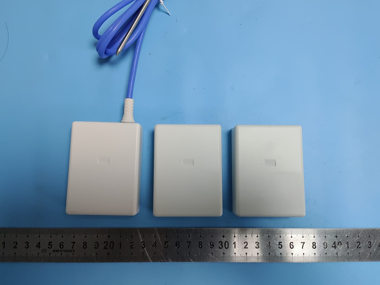
ZHZWTS
Nov 06, 2022WTS
Equipment Class
DSS - Part 15 Spread Spectrum Transmitter