ZKQ-PRSGSM Tracker
Micron Electronics LLC.
Click to zoom
Application Details
- Equipment Class
- PCB - PCS Licensed Transmitter
- Date of Grant
- Dec 19, 2013
- Application Purpose
- Original Equipment
- Date of Application
- Dec 19, 2013
- Equipment Note
- GSM Tracker
- Frequency Range
- 1850.20000000 - 1909.80000000
- Company
- Micron Electronics LLC.
- Country
- United States
Documents & Files
Document Text
Text extracted from the exhibit documents filed with the FCC. Open a document above to read the original.
Users Manual
1 PRIME PR100 User Manual Revision: 1.00 Document Title PR100 User manual Version 1.00 Finale Date 2013-10-25 Status Released Document Control ID PR100 2 Contents 1 Introduction....................................................................................................................................3 2 Product Overview ..........................................................................................................................3 2.1 Appearance..........................................................................................................................3 2.2 Buttons/Mini USB Interface Description ............................................................................3 2.3 LED Description .................................................................................................................4 3 Getting Started ...............................................................................................................................5 3.1 Parts List .............................................................................................................................5 3.2 Battery Charging .................................................................................................................5 3.3 PR100 Data Cable ...............................................................................................................5 3.4 How to insert SIM Card ......................................................................................................6 3.5 Power on/Power off.............................................................................................................7 3.6 Calls ....................................................................................................................................7 4 Trouble shooting and Safety info ...................................................................................................8 4.1 Trouble shooting .................................................................................................................8 4.2 Safety info ...........................................................................................................................8 5. Warning statement.........................................................................................................................8 3 1 Introduction PR100 is a mobile phone which mainly is used for emergency dialing with GSM frequencies 850/900/1800/1900. Based on the embedded wireless protocol, PR100 can communicate with the backend server through GPRS/GSM network, and transfer reports of emergency, gsm information and scheduled power level etc... Service provider is easy to setup their processing platform based on the functional wireless protocol. 2 Product Overview 2.1 Appearance Figure 1-1 2.2 Buttons/Mini USB Interface Description Button /Mini USB Interface Description KEY/interface Description Power Key Power on PR100 and initiate an emergency call. Note: Power off PR100 is automated whilst 5 minutes later after the call. 4 Mini USB interface Connect a 5V DC adapter can power on PR100 and charge the internal battery. Backend server developer or administrator can use the data cable to configure PR100. Reset Key Click the key will turn off internal VBAT when OS is abnormal, and then press Power Key to restart PR100. 2.3 LED Description Figure 1-2 There are red and blue LED lights in PR100 device, the description as following. Event Light State Power off Solid red Power on and normal Solid red AND solid blue Fully charged Slow flashing blue In charging Slow flashing red SOS call in progress Solid red Normal call in progress Solid blue Call failed (i.e. no signal) Solid red AND solid blue Low battery Fast flashing red 5 3 Getting Started 3.1 Parts List Name Picture Remark PR100 device The GSM/GPRS phone. AC-DC Power Adapter It is used to charge the internal battery of PR100. PR100 Data and charger Cable It is the USB data cable which can be used for firmware upgrading and configuration. It also includes the charger interface on the PR100. 3.2 Battery Charging The following items are suggestion for battery charge, please pay more attention. Please connect AC-DC power adapter with PR100 device. Insert the AC-DC power adapter into the power socket. During the charging process, the LED light will slow flash red. When the battery is fully charged, the LED light will be slow fashing blue. You can also charge the battery using USB cable which connects PR100 device with the PC. Charging will last about less than two hours. Note: If the PR100 device is firstly used, please make sure the battery is fully charged, which will make the life of battery much longer. 3.3 PR100 Data Cable PR100 Data Cable is a cable with a Mini USB connector. The USB data cable is used for firmware update or configuration and can be used for 6 charging at the same time. Figure 2-1 3.4 How to insert SIM Card Figure 2-2 Step1: Screw off and pull out the cover of SIM card. Step2: insert the SIM card into the slot of the device according to the direction as shown. Step3: push the cover back. 7 3.5 Power on/Power off Power on: Figure 2-3 Press the Power key at least 3 seconds and release it to power on PR100 device. Note that, the LED light will be solid red and solid blue. Power off: Power off is automated whilst 5 minutes later after the call. 3.6 Calls To make a call or answer a call, press the Power key once, the call can also be hung up by pressing the Power key. Note1: Be sure that the PR100 device is powered on before a call. Note2: The PR100 device can only support voice function via a speaker, and does not support the position against the ear or headset. 8 4 Trouble shooting and Safety info 4.1 Trouble shooting Trouble Possible Reason Solution Messages can’t be reported to the backend server by GPRS. The SIM card in PR100 doesn’t support GPRS. Try a GPRS supported SIM card. APN is wrong. Some APN can not v…
Text truncated - open the document above for the full version.
Cover Letter(s)
Stay Connected...... Qct 30, 2013 Federal Communications Commission, Authorization & Evaluation Division, 7435 Oakland Mills Road, Columbia, MD 21046 To Whom It May Concern: Micron Electronics LLC., the undersigned, hereby authorizes Ms. Xu Zhihong from CCIC Southern Electronic Product Testing (Shenzhen) Co., Ltd., to act on the behalf of Micron Electronics LLC. solely in matters relating to the application for an FCC equipment authorization for FCC ID #ZKQ-PRS including the signing of documents in connection with this Application. Necessary acts carried out by CCIC Southern Electronic Product Testing (Shenzhen) Co., Ltd. on behalf of Micron Electronics LLC in connection with the Application shall have the same effect as acts of Micron Electronics LLC. Micron Electronics LLC. also hereby certify that no party to this application is subject to a denial of benefits, including FCC benefits, pursuant to Section 5301 of the Anti-Drug Abuse Act of 1988, 21 U.S.C. 853(a). Thank you for your attention to this matter. Yours Sincerely, Ping Cheng Director Micron Electronics LLC. 600 N. Congress Ave. Suite 439 Delray Beach, FL 33445 561-252-1780
Cover Letter(s)
Micron Electronics LLC c Date: Nov 12, 2013 To: Federal Communications Commission, Authorization & Evaluation Division, 7435 Oakland Mills Road, Columbia, MD 21046 Re: Micron Electronics LLC FCC ID: ZKQ-PRS FCC Part 15C Certification Confidentiality Request Gentlemen: Pursuant of Sections 0.457 & 0.459 of the Commission’s Rules, Micron Electronics LLC requests that the following documents regarding this submission for FCC ID: ZKQ-PRS be kept confidential: Exhibit Type File Name Block Diagram CONF APPENDIX ZKQ-PRS_Block Diagram.pdf Schematics CONF APPENDIX ZKQ-PRS_Schematics.pdf Operational Description CONF APPENDIX ZKQ-PRS_Operation Description.pdf Part list CONF APPENDIX ZKQ-PRS_BOM.pdf Those documents contain detailed system and equipment description and related information about the product which Micron Electronics LLC considers to be confidential proprietary, a custom design and, otherwise, not releasable to the general public. Since this design is a basis form which future technological products will evolve, Micron Electronics LLC considers this information would be of benefit to its competitors, and that the disclosure of the information in these documents would give competitors an unfair advantage in the market. Ping Cheng Sales manager
Cover Letter(s)
Statement We MICRON ELECTRONICS LLC declare under our sole responsibility that the product (with one USB port): Product name: GSM Tracker Trade name: PRIME Type or model: PR100 The USB Port is only for charger, and can not do data communication with PC, which was performed as follow: The customer will only have the charging cable without any communication function with PC other than charging. There will be two pins on the Micro USB side of charging cable, one is +5V DC and the other one is GND. Ping cheng Nov 22. 2013
Internal Photos
Antenna
Parts List/Tune Up Info
DCS1800 Tune up description 1.Circuit Diagram and Working Theory The tracker used MediaTek platform. This platform has such advantages as less spare parts, lower cost ,stable capability and highly sensitive receive ability etc. The chipset is MT6252A that from MediaTek, MT6252A integrated RF transceiver for multi-band GSM and GPRS cellular systems. The amplifier is RPF88162B that from Renesas Company. 1. RF Part 1.1 Function description and diagram The main function of RF circuit is to send and receive the wireless documents and also to do document communication with chipset. The diagram is as follow: Figure1 RF BLOCK DIAGRAM PCS1900 GSM900 DCS1800 Renesas SAW Baseband MT6252A GSM850 PCS1900 SAW SAW GSM850 GSM900 1.2 Output power&Power control level GSM850 Power control level Transmitter output power (dBm) Tolerances (normal) 5 31 ±1dB 6 29 ±2dB 7 27 ±2 dB 8 25 ±2 dB 9 23 ±2 dB 10 21 ±2 dB 11 19 ±2dB 12 17 ±2 dB 13 15 ±2 dB 14 13 ±2 dB 15 11 ±2 dB 16 9 ±2dB 17 7 ±2 dB 18 5 ±2 dB 19 3 ±2 dB PCS1900 Power control level Transmitter output power (dBm) Tolerances (normal) 0 29 ±1dB 1 28 ±2dB 2 26 ±2 dB 3 24 ±2 dB 4 22 ±2 dB 5 20 ±2dB 6 18 ±2 dB 7 16 ±2 dB 8 14 ±2 dB 9 12 ±2dB 10 10 ±2 dB 11 8 ±2 dB 12 6 ±2 dB 13 4 ±2dB 14 2 ±2 dB 15 0 ±2 dB 1.3 Power versus time +4 dBc │ ┌───┐_ +1,0 dBc │ │ └─────────────/ /──────────────────┐ 0 dBc │ │ │ -1,0 dBc │ │ ┌─────────────/ /──────────────┐ │ -6 dBc * │ ┌──┘ │ │ └──┐ -30 dBc ** │ ┌───┘ │ │ └───┐ │ │ │ │ │ lowest limit │─┘ │ │ └ (see │ │<-------- (147 bits) -------->│ table 1) └─────────────────────────/ /──────────────────────── 10 8 10 7056/13=542,8 ms 10 8 10 Figure 2 : Power vs time template for normal bursts * For GSM 850: -4 dBc for power control level 16; -2 dBc for power control level 17; -1 dBc for power control levels 18 and 19. For PCS 1 900 MS: -4 dBc for power control level 11; -2 dBc for power control level 12; -1 dBc for power control levels 13, 14 and 15. ** For GSM 850: -30 dBc or -17 dBm, whichever is the higher. For PCS 1 900 MS: -30 dBc or -20 dBm, whichever is the higher. Table 1: Lowest measurement limit for power / time template lowest limit GSM850, GSM 900 -59 dBc or -54 dBm whichever is the highest, except for the timeslot preceding the active slot, for which the allowed level is equal to -59 dBc or -36 dBm, whichever is the highest DCS 1 800, PCS 1 900 -48 dBc or -48 dBm whichever is the highest 2 Chipset Part The main functions for Chipset are as follows: Process documents keeping and DSP, keypad inputting, communicating With RF module, RF power controlling, PM Module controlling, SIM card interface, Serial download interface and GPS .For details, please find theory diagram showed on Fig 1-2. The regular module and functions were showed comparatively on it. Figure3 Chipset circuit theory diagr
RF Exposure Info
Report No. SET2013-06862 CCIC-SET/T-I (00) Page 1 of 112 FCC SAR TEST REPORT Report No.: SET2013-06862 Product Name: GSM Tracker Brand Name: PRIME Model No.: PR100 FCC ID: ZKQ-PRS Applicant: Micron Electronics LLC Address: 601 North Congress Ave Suite 439, Delray Beach, FL 33445 Issued by: CCIC-SET Lab Location: Electronic Testing Building, Shahe Road,Xili, Nanshan District, Shenzhen, 518055, P. R. China Tel: 86 755 26627338 Fax:86 755 26627238 This test report consists of 113 pages in total. It may be duplicated completely for legal use with the approval of the applicant. It should not be reproduced except in full, without the written approval of our laboratory. The client should not use it to claim product endorsement by CCIC-SET. The test results in the report only apply to the tested sample. The test report shall be invalid without all the signatures of testing engineers, reviewer and approver. Any objections must be raised to CCIC-SET within 15 days since the date when the report is received. It will not be taken into consideration beyond this limit. Report No. SET2013-06862 CCIC-SET/T-I (00) Page 2 of 112 Test Report Product Name GSM Tracker Brand Name PRIME Model No PR100 FCC ID ZKQ-PRS Applicant Micron Electronics LLC Applicant Address 601 North Congress Ave Suite 439, Delray Beach, FL 33445 Manufacturer Micron Electronics LLC Manufacturer Address 601 North Congress Ave Suite 439, Delray Beach, FL 33445 Test Standards 47CFR §2.1093- Radiofrequency Radiation Exposure Evaluation: Portable Devices; FCC OET Bulletin 65 (Edition 97-01), Supplement C (Edition 01-01): Evaluating Compliance with FCC Guidelines for Human Exposure to Radiofrequency Electromagnetic Fields; ANSI C95.1–1999: IEEE Standard for Safety Levels with Respect to Human Exposure to Radio Frequency Electromagnetic Fields, 3 kHz to 300 GHz; IEEE 1528–2003: Recommended Practice for Determining the Peak Spatial-Average Specific Absorption Rate (SAR) in the Human Body Due to Wireless Communications Devices: Experimental Techniques; Test Result Pass Tested by 2013-11-08 Lu Lei,Test Engineer Reviewed by 2013-11-08 Shuangwen Zhang, Senior Egineer Approved by 2013-11-08 Wu Li’an,Manager Report No. SET2013-06862 CCIC-SET/T-I (00) Page 3 of 112 Contents 1. GENERAL CONDITIONS---------------------------------------------------------------4 2. ADMINISTRATIVE DATA--------------------------------------------------------------5 2.1. Identification of the Responsible Testing Laboratory-----------------------------5 2.2. Identification of the Responsible Testing Location(s) ----------------------------5 2.3. Organization Item-----------------------------------------------------------------------5 2.4. Identification of Applicant-------------------------------------------------------------5 2.5. Identification of Manufacture---------------------------------------------------------5 3. EQUIPMENT UNDER TEST (EUT)------------------------------------------------------6 4. OPERATIONAL CONDITIONS DURING TEST---------------------------------------7 4.1. Introduction------------------------------------------------------------------------------7 4.2. SAR Definition--------------------------------------------------------------------------7 4.3. Phantoms---------------------------------------------------------------------------------8 4.4. Device Holder---------------------------------------------------------------------------8 4.5. Probe Specification---------------------------------------------------------------------9 5. OPERATIONAL CONDITIONS DURING TEST----------------------------------10 5.1. Schematic Test Configuration-------------------------------------------------------10 5.2. SAR Measurement System-----------------------------------------------------------11 5.3. Equipments and results of validation testing--------------------------------------14 5.4. SAR measurement procedure-------------------------------------------------------16 5.5. Antennas position --------------------------------------------------------------------17 6. CHARACTERISTICS OF THE TEST------------------------------------------------19 6.1. Applicable Limit Regulations--------------------------------------------------------19 6.2. Applicable Measurement Standards------------------------------------------------19 7. LABORATORY ENVIRONMENT-----------------------------------------------------19 8. TEST RESULTS----------------------------------------------------------------------------20 8.1. Summary of Measurement Results -------------------------------------------------20 8.2. Conclusion------------------------------------------------------------------------------22 9. MEASUREMENT UNCERTAINTY----------------------------------------------------23 10. MAIN TEST INSTRUMENTS-----------------------------------------------------------25 This Test Report consists of the following Annexes: Annex A: Accreditation Certificate----------------------------------------------------26 Annex B: Test Layout --------------------------------------------------------------------28 Annex C: Sample Photographs --------------------------------------------------------33 Annex D: System Performance Check Data and Highest SAR plots-----------36 Annex E: Calibration Certificate of Probe and Dipoles---------------------------81 Report No. SET2013-06862 CCIC-SET/T-I (00) Page 4 of 112 1.GENERAL CONDITIONS 1.1 This report only refers to the item that has undergone the test. 1.2 This report standalone does not constitute or imply by its own an approval of the product by the certification Bodies or competent Authorities. 1.3 This document is only valid if complete; no partial reproduction can be made without written approval of CCIC-SET. 1.4 This report cannot be used partially or in full for publicity and/or promotional purposes without previous written approval of CCIC-SET. and the Accreditation Bodies, if it applies. Report No. SET2013-06862 CCIC-SET/T-I (00) Page 5 of 112 2. Administrative Date 2.1.…
Text truncated - open the document above for the full version.
Test Report
Report No.: SET2013-02952 CCIC-SET/T(00) Page 1 of 75 RF TEST REPORT Report No.: SET2013-02952 Product: GSM Tracker FCC ID: ZKQ-PRS Model No.: PR100 Applicant: Micron Electronics LLC Address: 601 North Congress Ave Suite 439, Delray Beach, FL 33445 Issued by: CCIC-SET Lab Location: Electronic Testing Building, Shahe Road,Xili, Nanshan District, Shenzh China Tel:86 755 26627338 Fax:86 755 26627238 This test report consists of 75 pages in total. It may be duplicated completely for legal use with the approval of the applicant. It should not be reproduced except in full, without the written approval of our laboratory. The client should not use it to claim product endorsement by CCIC-SET. The test results in the report only apply to the tested sample. The test report shall be invalid without all the signatures of testing engineers, reviewer and approver. Any objections must be raised to CCIC-SET within 15 days since the date when the report is received. It will not be taken into consideration beyond this limit. Report No.:SET2013-02952 CCIC-SET/T(00) Page 2 of 75 Product ................................. : Test Report GSM Tracker Model No. ............................ : PR100 Brand Name .......................... : PRIME Trade Name.......................: PRIME Applicant ............................... : Micron Electronics LLC Applicant Address ............... : 601 North Congress Ave Suite 439, Delray Beach, FL 33445 Manufacturer ........................ : Micron Electronics LLC Manufacturer Address ......... : 601 North Congress Ave Suite 439, Delray Beach, FL 33445 Test Standards ..................... : 47 CFR Part 2(10-1-09 Edition) Frequency Allocations and Radio Treaty Matters; General Rules and Regulations 47 CFR Part 22(10-1-09 Edition) Public Mobile Services 47 CFR Part 24(10-1-09 Edition)Personal Communications Services Test Date ............................... : June 14, 2013 to June 28, 2013 Tested by ............................. : 2013-07-05 Lu Lei, Test Engineer Reviewed by ......................... : 2013-07-05 Shuangwen Zhang, Senior Engineer Product ................................. : 2013-07-05 Wu Li’an, Manager Report No.:SET2013-02952 CCIC-SET/T(00) Page 3 of 75 Table of Contents 1. GENERAL INFORMATION .................................................................................................... 4 1.1 EUT Description ......................................................................................................................... 4 1.2 Test Standards and Results ........................................................................................................ 5 1.3 Facilities and Accreditations ...................................................................................................... 6 2. 47 CFR PART 2, PART 22H & 24E REQUIREMENTS ........................................................ 7 2.1 Conducted RF Output Power .................................................................................................... 7 2.2 99% Occupied Bandwidth ....................................................................................................... 15 2.3 Frequency Stability ................................................................................................................... 28 2.4 Conducted Out of Band Emissions ......................................................................................... 31 2.5 Band Edge ................................................................................................................................. 47 2.6 Transmitter Radiated Power (EIRP/ERP) ............................................................................. 52 2.7 Radiated Out of Band Emissions ............................................................................................ 61 Report No.:SET2013-02952 CCIC-SET/T(00) Page 4 of 75 1. GENERAL INFORMATION 1.1 EUT Description EUT Type.............................. : GSM Tracker Serial No. .............................. : FCC ID ................................. : (n.a, marked #1 by test site) ZKQ-PRS Hardware Version ................. : N/A Software Version ................... N/A Frequency Range .................. : GSM 850MHz: Tx: 824.20 - 848.80MHz (at intervals of 200kHz); Rx: 869.20 - 893.80MHz (at intervals of 200kHz) GSM 1900MHz: Tx: 1850.20 - 1909.80MHz (at intervals of 200kHz); Rx: 1930.20 - 1989.80MHz (at intervals of 200kHz) Modulation Type ................... : GPRS/GSM Mode with GMSK Modulation Multislot Class ...................... : GPRS: Multislot Class10 Antenna Type ........................ : PIFA Antenna Emission Designators ........... : GSM850:248KGXW, GSM1900:244KGXW, GPRS850:248KGXW,GPRS1900:248KGXW Note 1: The transmitter (Tx) frequency arrangement of the Cellular 850MHz band used by the EUT can be represented with the formula F(nq)=824.2+0.2*(n-128), 128<=n<=251; the lowest, middle, highest channel numbers (ARFCHs) used and tested in this report are separately 128 (824.2MHz), 190 (836.6MHz) and 251 (848.8MHz). Note 2: The transmitter (Tx) frequency arrangement of the PCS 1900MHz band used by the EUT can be represented with the formula F(n)=1850.2+0.2*(n-512), 512<=n<=810; the lowest, middle and highest channel numbers (ARFCHs) used and tested in this report are separately 512 (1850.2MHz), 661 (1880.0MHz) and 810 (1909.8MHz). Note 3: For a more detailed description, please refer to Specification or User’s Manual supplied by the applicant and/or manufacturer. Report No.:SET2013-02952 CCIC-SET/T(00) Page 5 of 75 1.2 Test Standards and Results The objective of the report is to perform testing according to 47 CFR Part 2, Part 22 and Part 24 for the EUT FCC ID Certification: No. Identity Document Title 1 47 CFR Part 2 (10-1-09 Edition) Frequency Allocations and Radio Treaty Matters; General Rules and Regulations 2 47 CFR Part 22 (10-1-09 Edition) Public Mobile Services 3 47 CFR Part 24 (10-1-09 Edition) Personal Communications Services Test det…
Text truncated - open the document above for the full version.
Contact Information
Applicant
Ping Cheng(Director)
Test Firm
CCIC-SETQi Zhu
Technical Specifications
| # | Rule Parts | Frequency Range | Power Output | Emission | Tolerance |
|---|---|---|---|---|---|
| 2 | 24E | 1.85 GHz - 1.91 GHz | 860.00 mW | 248KGXW | 0.1 ppm |
Other Applications from Micron Electronics LLC.
ZKQ-PT102V
Apr 04, 2024Tracker
Equipment Class
JAB - Part 15 Class B Digital Device
ZKQ-AHALO
Aug 31, 2023Tracker
Equipment Class
JAB - Part 15 Class B Digital Device
ZKQ-WB100
Aug 23, 2023WB100
Equipment Class
PCT - PCS Licensed Transmitter worn on body
ZKQ-G601
Jun 26, 2023Tracker
Equipment Class
DSC - Part 15 Security/Remote Control Transmitter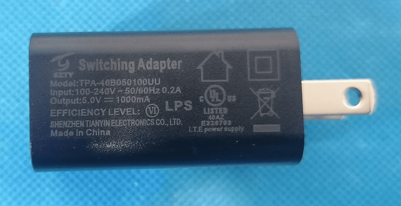
ZKQ-ATP4GA2
Jun 26, 2023Tracker
Equipment Class
PCB - PCS Licensed Transmitter