ZLCUNI13Q60USBXRFID Read/Write Module UNI13-Q60-USB
Microsensys GmbH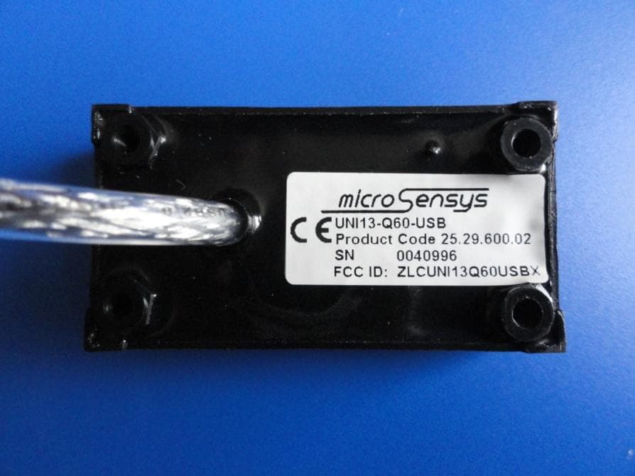
Click to zoom
Application Details
- Equipment Class
- DXT - Part 15 Low Power Transceiver, Rx Verified
- Date of Grant
- Jul 24, 2011
- Application Purpose
- Original Equipment
- Date of Application
- Jul 24, 2011
- Equipment Note
- RFID Read/Write Module UNI13-Q60-USB
- Frequency Range
- 13.56000000 - 13.56000000
- Company
- Microsensys GmbH
- Country
- Germany
Documents & Files
Document Text
Text extracted from the exhibit documents filed with the FCC. Open a document above to read the original.
Users Manual
User Manual UNI13-Q60-232 / UNI13-Q60-USB RFID read/write module 13.56 MHz closed coupling iID ® Reader Page 2 ©2011 microsensys GmbH User Manual UNI13-Q60-232 / -USB Contact/Copyright microsensys GmbH Office Park im GVZ In der Hochstedter Ecke 2 99098 Erfurt Germany tel: +49 (0) 3 61/5 98 74-0 fax: +49 (0) 3 61/5 98 74-17 e-mail: [email protected] homepage: www.microsensys.de User Manual UNI13-Q60-232 / -USB ©2011 microsensys GmbH Page 3 FCC Compliance Statement These devices comply with part 15 of the FCC Rules. Operation is subject to the following two conditions: 1. These devices may not cause harmful interferences; 2. These devices must accept any interference received, including interference that may cause undesired operation. The following figures list the Grant by FCC ID Number for each of the following devices: UNI13-Q60-232 FCC ID: ZLCUNI13Q60232X UNI13-Q60-USB FCC ID: ZLCUNI13Q60USBX Please refer to the FCC’s website ( http://www.fcc.gov/ ) to view the grant and related documentation. CAUTION ! Exposure to Radio Frequency Radiation. The radiated output of this device is far below the FCC radio frequency exposure limits. Nevertheless, the device shall be used in such a manner that the potential for human contact during normal operation is minimized. In order to avoid the possibility of exceeding the FCC radio frequency exposure limits, human proximity to the antenna shall not be less than 20cm (8inches) during normal operation. These devices may not be co-located with any other transmitter or transmitter antenna. NOTE: This equipment has been tested and found to comply with the limits for a Class A digital device, pursuant to part 15 of the FCC Rules. These limits are designed to provide reasonable protection against harmful interferences when the equipment is operated in a commercial environment. This equipment generates, uses, and can radiate radio frequency energy and, if not installed and used in accordance with the instruction manual, may cause harmful interference to radio communications. Operation of this equipment in a residential area is likely to cause harmful interference in which case the user will be required to correct the interference at his own expense. Changes or modifications not expressly approved by Microsensys GmbH could void the user’s authority to operate the equipment described in the manual. Page 4 ©2011 microsensys GmbH User Manual UNI13-Q60-232 / -USB Introduction The RFID read/write module UNI13-Q60 is part of the inductive read/write- identification system iID ® 3000 and serves for the reading and writing of 13.56MHz RFID transponders. It supports RFID transponder systems like iID ® , TELID ® , ISO15693, I-CODE™, tag-it™, my-D™, LEGIC ® and further. The UNI16-Q60 is available in two types, with a serial interface and with a USB interface to the host computer. This product is designed for use in industrial environment together with a host, such as handheld devices or laptops. The small size and the integrated antenna on the front side of the UNI13-Q60 module allow a simple use in many different applications. For the mechanical mounting of the module four threads for screws on the back side may use. Please read this document carefully to prevent damage and unwanted results. User Manual UNI13-Q60-232 / -USB ©2011 microsensys GmbH Page 5 Technical Data Housing: plastic case with integrated antenna, epoxy molded Size: 55mm x 29mm x 12mm (without cable or connector) Temperatur range: Operating: 0 ... +50 °C Storage: -25 ... + 70°C Power supply (VCC): 5V +/- 5%, ripple <50mV Current consumption: typ. 100mA (active mode, with active RF field) typ. 10mA (idle mode, without RF field) Connector: serial interface: USB interface: BLR 125Z, standard USB Type A Fischer Elektronik Voltage Level: serial interface: USB interface: high: 0.85*VCC ... VCC according USB 1.1 standard low: GND ... 0.15*VCC Protocol: baudrate: 57.6 kabaud data bits: 8 stop bits: 1 parity: no Software interface: iID ® Driver Engine for Windows Supported Commands: see actual API documentation of iID ® Driver Engine Page 6 ©2011 microsensys GmbH User Manual UNI13-Q60-232 / -USB RFID air interface Carrier frequency: 13.56MHz +/- 7kHz RF output power: 200mW Implemented standards: ISO15693, ISO14443B Anticollision: not implemented Antenna type: P13 Operating distance: 0 ... 50 mm depending on transponder type and environment conditions Ordering information Product Product code UNI13-Q60-232 25.26.603.02 UNI13-Q60-USB 25.29.600.02 User Manual UNI13-Q60-232 / -USB ©2011 microsensys GmbH Page 7 Safety instructions ● The device may only be used for the intended purpose designed by for the manufacturer. ● Unauthorized changes and the use of spare parts and additional devices which have not been sold or recommended by the manufacturer may cause fire, electric shocks or injuries. Such unauthorized measures shall exclude any liability by the manufacturer. ● The liability-prescriptions of the manufacturer in the issue valid at the time of purchase are valid for the device. The manufacturer shall not be held legally responsible for inaccuracies, errors, or omissions in the manual or automatically set parameters for a device or for an incorrect application of a device. ● Repairs may only be executed by the manufacturer. ● Installation, operation, and maintenance procedures should only be carried out by qualified personnel. ● Use of the device and its installation must be in accordance with national legal requirements and local electrical codes. ● When working on devices the valid safety regulations must be observed. Questions? Contact us: microsensys GmbH Office Park im GVZ In der Hochstedter Ecke 2 D-99098 Erfurt Germany e-mail: [email protected] tel: +49 361 59874 0 fax: +49 361 59874 17 © 2011 microsensys GmbH Every reproduction of the document in hand or storing in electronic media, as well as translation in other languages is not allowed without a written approval of MICROSENSYS GmbH. All rights re…
Text truncated - open the document above for the full version.
Cover Letter(s)
~~~~~~~~~ ~~~~ ~~~~ ~~~~~~~~~~~~~~~~~~~~~~~~~~~~~~~ ~~~~~~~~~~~~~~~~~~~~ ~~~~~~~~~~~~~~~~ ~~~~~~~~~~~~~~~~~~~~~~~~~~~~~~~~~~~~~~~~~~~~~~~~~~~~~~~~~~~~~~~~~~~~~~~~~~~~~ ~~~~~~~~~~~~~~~~~~~~~~~~~~~~~~~~~~~~~~~~~~~~~~~~~~~~~~~~~~~~~~~~~~~~~~~~~~~~~ ~~~~~~~~~~~~~~~~~~~~~~~~~~~~~~~~~~~ ~ ~~~~~~~~~~~~~~~~~~~~~~~~~~~~~~~ ~~~~~~~~~~~~~~~~~~~~~~~~~~~~~~~~~~~~~~~~~~ ~~~~~~~~~~~~~~~~~~~~~~~~~~~~~~ ~~~~~~~~~~~~~~~~~~~~~~~~~~~~~~~~~~~~~~~~~~~~~~~~~~~~~~~~~~~~~~~~~~~~~~~~~~~~ ~~~~~~~~~~~~~~~~~~~~~~~~~~~~~~~~~~~~~~~~~~~~~~~~~~~~~~~~~~~~~~~~~~~~~~~~~~ ~~~~~~~ ~~~~~~~~~~~~ ~~~~~~~~~~~~~~~~~ ~~~~~~~~~~~~~~~ ~~~~~~~~~~~~~~~~~ ~~~~~~~~~ ~~~~~~~~~~~~~ ~~~~~~~~~~~~~ ~~~~~~~~~~~~~~~~~~ ~~~~~~~~~~~ ~~~~~~~~ ~~~~~~~~~~~~~~~~~~~~~~~~~~ ~~~~~~~~~~~~~~~~~~~~~~~~~~~~~ ~~~~~~~~~~~~~~~~~~~~~~~~~~~~~~ ~~~~~~~~~~~~~~~~~~~~~ ~~~~~~~~~~~~
External Photos
UNI13-Q60-USB: External Photos
Internal Photos
UNI13-Q60-USB: Internal Photos
Test Report
SLG Prüf- und Zertifizierungs GmbH Burgstädter Straße 20 D – 09232 Hartmannsdorf Test report Radio module (RFID-Reader) [Funkmodul (RFID-Reader)] UNI13-Q60-USB Test plan of customer FCC rules Radio test 1040-10-EE-11-PB004 Testing is a confidential matter Test report no. [Prüfbericht- Nr.]: 1040-10-EE-11-PB004 Date [Datum]: 2011-07-21 Revised by [geprüft]: Tested by [gemessen]: Cromm Puder EMC laboratory [EMV-Labor] EMC laboratory [EMV-Labor] SLG Prüf- und Zertifizierungs GmbH Burgstädter Straße 20 D-09232 Hartmannsdorf EMC laboratory Phone: +49 (0) 37 22 / 73 23 - 760 Fax: +49 (0) 37 22 / 73 23 - 899 e-mail: [email protected] http://www.slg.de.com This report consists of [Dieser Bericht besteht aus]: 39 Pages [Seiten] Customer [Auftraggeber] microsensys GmbH Represented by [vertreten durch] In der Hochstedter Ecke 2 Mr. [Herr] Peitsch, Peter 99098 Erfurt, Germany [Deutschland] (was present temporarily / [war zeitweise anwesend]) Order [Auftrag] Dated [vom]: 2010-08-25 Order no. [Auftragsnr.]: D-362-10 Aim of test [Zweck der Prüfung] Verification of conformity to the radio requirements according to customer’s test plan [Nachweis der Einhaltung der Funk- Anforderungen nach Prüfplan des Auftraggebers] Product [Erzeugnis] Radio module (RFID-Reader) [Funkmodul (RFID-Reader)] Type [Typ] UNI13-Q60-USB Manufacturer [Hersteller] microsensys GmbH In der Hochstedter Ecke 2 99098 Erfurt, Germany [Deutschland] Date of test [Prüfzeitraum] 2011-01-14 – 2011-01-26 Location of test [Prüfungsort] Accredited EMC laboratory of the SLG Prüf- und Zertifizierungs GmbH Hartmannsdorf [akkreditiertes EMV-Labor der SLG Prüf- und Zertifizierungs GmbH Hartmannsdorf] Test according to [Prüfung nach] Customer’s specifications / test plan [Lastenheft / Prüfplan des Auftraggebers] Test base [Prüfgrundlage] CFR 47 FCC Part 15 (10-1-09 Edition) Test result [Prüfergebnis] The sample tested fulfills the radio requirements according to test plan of customer. [Der vorgestellte Prüfling erfüllt die Funk- Anforderungen nach Prüfplan des Auftraggebers.] The test results refer to the tested samples only. Authorisation for the copying of details of this report must be obtained from the SLG Prüf- und Zertifizierungs GmbH. [Die Prüfergebnisse beziehen sich ausschließlich auf die in diesem Bericht genannten Prüfungsgegenstände. Die auszugsweise Ver- vielfältigung dieses Berichtes für Dritte ist nur mit schriftlicher Genehmigung der SLG Prüf- und Zertifizierungs GmbH gestattet.] Test report no. [Prüfbericht-Nr.]: 1040-10-EE-11-PB004 Page [Seite] 3 Details of accreditation / recognition status [Einzelheiten zu Akkreditierungen / Anerkennungen] The SLG EMC laboratory is accredited by the German Association for Accreditation (DGA) [Das SLG EMV-Labor ist akkreditiert durch die DGA Deutsche Gesellschaft für Akkreditierung mbH] DAR registration number [DAR-Registriernummer]: DGA-PL-205/97-02 The SLG EMC laboratory is appointed as technical service of category A by the Federal Motor Transport Authority (KBA) [Das SLG EMV-Labor ist benannt als Technischer Dienst der Kategorie A von der Benennungsstelle des Kraftfahrt-Bundesamtes (KBA)] Registration number [Registriernummer]: KBA-P 00030-01 The Notified Body according to EMC directive is recognized by the Federal Network Agency for Electricity, Gas, Telecommunications, Post and Railway [Die Benannte Stelle nach EMV-Richtlinie ist anerkannt durch die Bundesnetzagentur für Elektrizität, Gas, Telekommunikation, Post und Eisenbahn (Bundesnetzagentur)] BNetzA registration number [Registriernummer]: BnetzA-bS EMV-07/61-13 The SLG EMC laboratory is recognized by the Federal Railway Authority (EBA) [Das SLG EMV-Labor ist anerkannt durch das Eisenbahn-Bundesamt (EBA)] Number of identification [Identifikationsnummer]: EBA - 28 / 08 / 05 The SLG EMC laboratory is listed by the Federal Communications Commission (FCC) [Das SLG EMV-Labor ist gelistet bei der Federal Communications Commission (FCC)] Registration number [Registrierungsnummer]: 883849 The SLG EMC laboratory is listed by the Industry Canada Certification and Engineering Bureau [Das SLG EMV-Labor ist gelistet beim Industry Canada Certification and Engineering Bureau] Company number [Firmennummer]: 6114A Test report no. [Prüfbericht-Nr.]: 1040-10-EE-11-PB004 Page [Seite] 4 Contents [Inhalt] 1 General information [Allgemeines] ................................................................................................. 5 1.1 Report chronology [Berichtschronologie] ............................................................................... 5 1.2 Declaration concerning the translation German / English [Erklärung zur Übersetzung Deutsch / Englisch] .................................................................... 5 1.3 General test conditions [Allgemeine Prüfbedingungen] ......................................................... 5 2 Summary of Radio test results [Übersicht über die Funk-Prüfergebnisse] ................................ 7 3 Description of the test sample [Angaben zum Prüfling] ............................................................... 8 4 Emission tests [Störaussendungsprüfungen] ............................................................................. 14 4.1 Measurement of field strength within the band 13.110 – 14.010 MHz [Messung der Feldstärke im Frequenzband 13.110 – 14.010 MHz] .................................... 14 4.2 Measurement of field strength outside of the 13.110 – 14.010 MHz band [Messung der Feldstärke außerhalb dem 13.110 – 14.010 MHz Frequenzband] ............... 21 4.3 Measurement of frequency tolerance [Messung der Frequenzstabilität] ......................................................................................... 36 5 List of test equipment [Messmittel und Prüfgeräte] .................................................................... 39 Test report no. [Prüfbericht-Nr.]: 1040-10-EE-11-PB004 Page [Seite] 5 1 General information [Allgemeines] 1.1 Report chronology [Berichtschronologie] Re…
Text truncated - open the document above for the full version.
Test Setup Photos
Pictures-1040-10-EE-11-PB002.pdf Page [Seite] 1 View of the EUT [Prüflingsansicht] Figure 1: Total view of EUT and additional equipment [Gesamtansicht des Prüflings und Zusatzgeräte ] Figure 2: Plan view of EUT [Draufsicht des Prüflings] Figure 3: Interior view of RFID- reader, without case [Innenansicht des RFID- Reader; ohne Gehäuse] Interior view of RFID- reader, without case [Innenansicht des RFID- Reader; ohne Gehäuse] Figure 4: Detailed view of battery box with signal ports [Detailansicht der Batteriebox mit Signalanschlüssen] Figure 5: Detailed view of battery box with signal ports [Detailansicht der Batteriebox mit Signalanschlüssen] Pictures-1040-10-EE-11-PB002.pdf Page [Seite] 2 Figure 6: Interior view of battery box with signal ports [Innenansicht der Batteriebox mit Signalanschlüssen] Figure 7: Transponder [Transponder] Figure 8: Measurement set-up for radiated measurement acc. to following sections of the report 1040-10-EE-11-PB002: 4.1 and 4.2.1 Pictures-1040-10-EE-11-PB002.pdf Page [Seite] 3 Figure 9: Measurement set-up for radiated measurement acc. to following sections of the report 1040-10-EE-11-PB002: 4.2.2 and 4.2.3 Figure 10: Measurement set-up for radiated measurement acc. to following sections of the report 1040-10-EE-11-PB002: 4.3
Contact Information
Applicant
Peter Peitsch
Test Firm
SLG Pruef- und Zertifizierungs GmbHRonald Svadlenka
Technical Specifications
| # | Rule Parts | Frequency Range | Power Output |
|---|---|---|---|
| 1 | 15C | 13.56 MHz - 13.56 MHz | - |
Other Applications from Microsensys GmbH
ZLCUNI13Q60232X
Jul 24, 2011RFID Read/Write Module UNI13-Q60-232
Equipment Class
DXT - Part 15 Low Power Transceiver, Rx Verified