ZME-WIDPWI-DRIVE+ (WIDP)
Kingston Digital Inc.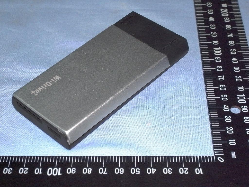
Click to zoom
Application Details
- Equipment Class
- DTS - Digital Transmission System
- Date of Grant
- Nov 20, 2012
- Application Purpose
- Original Equipment
- Date of Application
- Nov 20, 2012
- Equipment Note
- WI-DRIVE+ (WIDP)
- Frequency Range
- 2412.00000000 - 2462.00000000
- Company
- Kingston Digital Inc.
- Country
- United States
Documents & Files
Document Text
Text extracted from the exhibit documents filed with the FCC. Open a document above to read the original.
Users Manual
WIDP Getting Started Step 1 – Charge your WIDP Device Before using, make sure your WIDP™ is fully charged. To charge, connect the included USB cable to your WIDP’s mini USB port (1) and the other end into an available USB port on your computer or to a USB wall adapter. The green power light will stop _ashing when WIDP is fully charged. Step 2 – Add Content to your WIDP Windows users: When connecting your WIDP to your computer, two drive letters will appear in Windows Explorer — one Read-Only labeled “CDROM” and one Removable Disk labeled “WIDP” Double-click on the drive labeled “WIDP” to add your content. Transfer your _les the same as you would for any USB drive; drag or copy _les from your computer to your WIDP device Mac users: By default when connecting your WIDP to your computer, two drives will appear on your desktop — one Read-Only labeled “CDROM” and one Removable Disk labeled “WIDP” Double-click on the drive labeled “WIDP” to add your content. Transfer your _les the same as you would for any USB drive; drag or copy _les from your computer to your WIDP device. (It is recommended that you organize your content by creating folders, e.g., “Videos, Music, Pictures and Documents”) Step 3 – Download Kingston’s Free WIDP App from the App Store Visit Apple’s App Store and search for “Kingston WIDP”. Figure 1 – Kingston’s WIDP App Icon Step 4 Power on the WIDP by pressing the On/Off button (2).* *Note: After you power on, wait for Blue Wi-Fi Activity Light to start _ashing before proceeding to the next step(3). Step 5 Go to the Settings icon on your iPad®, iPhone®, or iPod® touch and select Wi-Fi. Con_rm that Wi-Fi is ON. Select “Kingston WIDP” under “Choose a Network” and click on it to connect to it. Step 6 Once connected, open the Kingston WIDP app on your iPad, iPhone, or iPod touch and enjoy your new expanded storage. Step 7 Share your content with as many as three users by having them follow steps 3 to 6. 中文版使用手冊 無線硬碟讀卡機 型號:WIDP 步驟1-為您的WIDP充電 在使用前,請先確認您的WIDP已經充飽電量。若需充電,請將附贈的USB線連接至WIDP的 miniUSB埠(1),另一端插入電腦上可用的USB插槽或USB電源轉接器即可。當WIDP充飽電 量後,綠色指示燈會停止閃爍。 步驟2-將資料傳輸至您的WIDP Windows作業系統的使用者:將您的WIDP連接上電腦後,Windows檔案總管會出現兩個磁碟 代號-一個標示為「CDROM」 的唯讀光碟機,另一個標示為「WIDP」的卸除式磁碟。在標示 為「WIDP」的磁碟點擊兩下即可新增檔案。傳輸檔案的方式與使用一般USB隨身碟相同;您 只需將電腦中的檔案拖曳或複製到WIDP即可 Mac作業系統的使用者:將您的WIDP連接上電腦後,Windows檔案總管會出現兩個磁碟代號 -一個標示為「CDROM」 的唯讀光碟機,另一個標示為「WIDP」的卸除式磁碟。在標示為「WIDP」 的磁碟點擊兩下即可新增檔案。傳輸檔案的方式與使用一般USB隨身碟相同;您只需將電腦中 的檔案拖曳或複製到WIDP即可。(建議您建立資料夾來組識您的檔案,例如「影片、音樂、圖 片和文件」) 步驟3-從App Store(下載 免費的Kingston WIDP應用程式 您可連結至Apple的App Store(並輸入「Kingston WIDP」搜尋。 步驟4 按下On/Off按鈕(2)以開啟WIDP電源。 *請注意:當電源開啟後,請等候藍色的Wi-Fi指示燈開始閃爍,再繼續下一個操作步驟(3)。 步驟5 在iPad®、iPhone®或 iPod® touch的「設定」功能中點選Wi-Fi功能。確認開啟啟Wi-Fi功能。 在「選擇網路」下選取「Kingston WIDP」並開啟連線。 步驟6 連線之後開啟iPad®、iPhone®或 iPod® touch上的Kingston WIDP應用程式,即可開始使用 WIDP的儲存空間。 步驟7 遵循步驟3至6的程序,您即可透過WIDP最多同時與三位使用者分享檔案資料。 注意事項: NCC警語 第十二條:經型式認證合格之低功率射頻電機,非經許可,公司、商號或使用者均 不得得擅自變更頻率、加大功率或變更通原計之特性及功能。 第十四條:低功率射頻電機之使用不得影響飛航安全及干擾合法通信;經發現有干 擾現象時,應立即停用,並改善至無干擾時方得繼續使用。 前項合法通信,指依電信法規定作業之無線電通信。低功率射頻電機須忍受合法通 信或工業、科學及醫療用電波輻射性電機設備之干擾。 FCC Compliance and Advisory Statement This device complies with Part 15 of the FCC rules. Operation is subject to the following two conditions:(1) this device may not cause harmful interference, and (2) this device must accept any interference received, including interference that may cause undesired operation. This equipment has been tested and found to comply with the limits for a Class B digital device, according to Part 15 of the FCC rules. These limits are designed to provide reasonable protection against harmful interference in a residential installation. This equipment generates, uses and can radiate radio frequency energy and if not installed and used in accordance with the instructions, may cause harmful interference to radio communications. However, there is no guarantee that interference will not occur in a particular installation. If this equipment does cause harmful interference to radio or television reception, which can be determined by turning the equipment off and on, the user is encouraged to try correct the interference by one or more of the following measures: 1.Reorient the receiving antenna. 2.Increase the separation between the equipment and receiver. 3.Connect the equipment into and outlet on a circuit different from that to which the receiver is connected. 4.Consult the dealer or an experienced radio/TV technician for help. Any special accessories needed for compliance must be specified in the instruction manual. Warning: A shielded-type power cord is required in order to meet FCC emission limits and also to prevent interference to the nearby radio and television reception. It is essential that only the supplied power cord be used. Use only shielded cables to connect I/O devices to this equipment. CAUSION: Any changes or modifications not expressly approved by the party responsible for compliance could void your authority to operate the equipment. FCC ID: ZME-WIDP Required notices to the User of Canada (RSS) Radio apparatus shall comply with the requirements to include required notices or statements to the user of equipment with each unit of equipment model offered for sale. The required notices are specified in the RSS documents (including RSS-Gen) applicable to the equipment model. These notices are required to be shown in a conspicuous location in the user manual for the equipment, or to be displayed on the equipment model. If more than one notice is required, the equipment model(s) to which each notice pertains should be identified. Suppliers of radio apparatus shall provide notices and user information in both English and French. IC statementThis Class B digital apparatus complies with Canadian ICES‐003.Cet appareil
Cover Letter(s)
Kingston Digital Inc. 17600 Newhope Street, Fountain Valley, CA 92708 USA Tel 714.435.2600 Fax 714.435.2699 www.kingston.com Power of Attorney Federal Communications Commission Authorization and Evaluation Division 7435 Oakland Mills Road Columbia, MD 21046 To whom it may concern: This is to serve as proper written authorization that Spectrum Research and Testing Laboratory, Inc., Johnson Ho, will act as our representative in all matters relating to FCC applications for equipment approval. This includes the signing of all related documents, the transmitting of required fees, and receiving correspondence and notifications from the FCC. All acts performed by Spectrum Research and Testing Laboratory, Inc., especially modifications to our equipment under testing will be carried out on our behalf. Meantime, the applicant certifies that in the case of an individual applicant (e.g., corporation), no party to the applicant is subject to a denial of federal benefits, that includes FCC benefits, pursuant to Section 5301 of the Anti-Drug Abuse Act of 1998,21 U.S.C. 862. For a definition of a " party " for these purposes see 47 C.F.R. 1.2002 (b). If you have any questions regarding our applications for equipment approval, please contact Spectrum Research and Testing Laboratory, Inc. Johnson Ho, by [email protected] . or Kingston Digital, Inc. Contact Person Lawrence Kao by [email protected] . Respectfully, _________________________ Effective date: Lawrence Kao From: 11/03/2012 to 11/02/2013 Corporate Operational Compliance
External Photos
Spectrum Research & Testing Lab., Inc. No. 101-10, Ling 8, Shan-Tong Li, Chung-Li City, Taoyuan, Taiwan Taiwan, R.O.C. PHOTOS OF EUT
ID Label/Location Info
Spectrum Research & Testing Lab., Inc. No. 101-10, Ling 8, Shan-Tong Li, Chung-Li City, Taoyuan, Taiwan Taiwan, R.O.C. FCC ID:ZME-WIDP
Internal Photos
Spectrum Research & Testing Lab., Inc. No. 101-10, Ling 8, Shan-Tong Li, Chung-Li City, Taoyuan, Taiwan Taiwan, R.O.C. TOP inside Spectrum Research & Testing Lab., Inc. No. 101-10, Ling 8, Shan-Tong Li, Chung-Li City, Taoyuan, Taiwan Taiwan, R.O.C. PCB-F PCB-F (IC-1) Chip Antenna Wifi module Spectrum Research & Testing Lab., Inc. No. 101-10, Ling 8, Shan-Tong Li, Chung-Li City, Taoyuan, Taiwan Taiwan, R.O.C. PCB-F (IC-2) Spectrum Research & Testing Lab., Inc. No. 101-10, Ling 8, Shan-Tong Li, Chung-Li City, Taoyuan, Taiwan Taiwan, R.O.C. PCB-B PCB-F (IC-1) Spectrum Research & Testing Lab., Inc. No. 101-10, Ling 8, Shan-Tong Li, Chung-Li City, Taoyuan, Taiwan Taiwan, R.O.C. Port Spectrum Research & Testing Lab., Inc. No. 101-10, Ling 8, Shan-Tong Li, Chung-Li City, Taoyuan, Taiwan Taiwan, R.O.C. Battery Spectrum Research & Testing Lab., Inc. No. 101-10, Ling 8, Shan-Tong Li, Chung-Li City, Taoyuan, Taiwan Taiwan, R.O.C. CASE
Operational Description
TECHNOLOGICAL SPEC. 1. Product Name: Wi-Drive+ Model: WIDP 2. Power Source: ■ DC 3.7 V, mA; □ AC V, A 3. Frequency Band: 2.4 GHz ~ 2.4835 GHz Carrier Frequency: 2.412 GHz ~ 2.462 GHz 4. Number of Channel: 11 (802.11n – HT20) 5. Channel Spacing: 6. RF Output Power (ERP or EIRP) : 13.48 dBuV/m 22.28 mW 7. I.F.: MHz; L.O.: MHz 8. Modulation Type: IEEE802.11n – HT20 SISO-OFDM (BPSK/16QAM/64QAM) 9. Duty Cycle: % 10. Mode of operation (duplex, simplex, half duplex) : half duplex 11. Bit Rate of Transmission:802.11n – HT20:MCS0~MCS7 (Max. 72.2 Mbps) 12. Antenna Type: Chip Antenna 13. Antenna gain: 2.88 dBi 14. Operating Temperature Range: -20 ~ 50 °C 15. Channel bandwidth : 20 MHz (802.11n – HT20)
Test Report
Spectrum Research & Testing Lab., Inc. No.167,Ln. 780, Shan-Tong Rd.,Ling 8, Shan-Tong Li, Chung-Li City, Taoyuan County 320, Taiwan (R.O.C.) TEST REPORT Reference No.: A12110102 Report No.:FCCA12110102 FCC ID : ZME-WIDP Page: 1 of 46 Date: Nov. 16, 2012 FMNG-059.10 REPORT Product Name: Wi-Drive+ Model No.: WIDP Applicant: Kingston Digital, Inc. 17600 Newhope Street Fountain Valley, CA 92708, U.S.A Date of Receipt: Nov. 01, 2012 Finished date of Test: Nov. 16, 2012 Applicable Standards: 47 CFR Part 15, Subpart C ANSI C63.4: 2003 KDB 558074-D01; Oct 2012” The FCC has made this KDB a requirement went testing DTS devices. We, Spectrum Research & Testing Laboratory Inc., hereby certify that one sample of the above was tested in our laboratory with positive results according to the above-mentioned standards. The records in the report are an accurate account of the results. Details of the results are given in the subsequent pages of this report. Tested By : , Date: Approved By : (Richard Lin) , Date: ( Johnson Ho, Director ) Spectrum Research & Testing Lab., Inc. No.167,Ln. 780, Shan-Tong Rd.,Ling 8, Shan-Tong Li, Chung-Li City, Taoyuan County 320, Taiwan (R.O.C.) TEST REPORT Reference No.: A12110102 Report No.:FCCA12110102 FCC ID : ZME-WIDP Page: 2 of 46 Date: Nov. 16, 2012 FMNG-059.10 REPORT Revisions History Report No. Issue Date Revisions FCCA12110102 Nov. 15, 2012 Initial issue FCCA12110102 Nov. 16, 2012 P1, update Applicable Standards P11, 4.1.2 TEST EQUIPMENT add LOOP ANTENNA P12, 4.1.3 TEST SET-UP add 9kHz~30MHz P30, 4.3.6 update TEST RESULT P43 6. PHOTOS OF TESTING add below 30MHz Spectrum Research & Testing Lab., Inc. No.167,Ln. 780, Shan-Tong Rd.,Ling 8, Shan-Tong Li, Chung-Li City, Taoyuan County 320, Taiwan (R.O.C.) TEST REPORT Reference No.: A12110102 Report No.:FCCA12110102 FCC ID : ZME-WIDP Page: 3 of 46 Date: Nov. 16, 2012 FMNG-059.10 REPORT Table of Contents 1. DOCUMENT POLICY AND TEST STATEMENT...................................................5 1.1 DOCUMENT POLICY.........................................................................................5 1.2 TEST STATEMENT............................................................................................5 1.3 EUT MODIFICATION..........................................................................................5 2. DESCRIPTION OF EUT AND TEST MODE.........................................................6 2.1 GENERAL DESCRIPTION OF EUT...................................................................6 2.2 DESCRIPTION OF EUT INTERNAL DEVICE....................................................6 2.3 DESCRIPTION OF TEST MODE........................................................................7 2.4 DESCRIPTION OF SUPPORT UNIT..................................................................8 2.5 EUT OPERATING CONDITION..........................................................................8 3. DESCRIPTION OF APPLIED STANDARDS.........................................................9 3.1 SUMMARY OF TEST RESULTS........................................................................9 4.1 RADIATED EMISSION TEST...........................................................................10 4.1.1 LIMIT..............................................................................................................10 4.1.2 TEST EQUIPMENT.......................................................................................11 4.1.3 TEST SET-UP................................................................................................12 4.1.4 TEST PROCEDURE......................................................................................14 4.1.5 TEST RESULT...............................................................................................15 4.2 BANDWIDTH TEST..........................................................................................26 4.2.1 LIMIT..............................................................................................................26 4.2.2 TEST EQUIPMENT.......................................................................................26 4.2.3 TEST SET-UP................................................................................................26 4.2.4 TEST PROCEDURE......................................................................................26 4.2.5 EUT OPERATING CONDITION.....................................................................26 4.2.6 TEST RESULT...............................................................................................27 4.3 PEAK POWER TEST........................................................................................29 4.3.1 LIMIT..............................................................................................................29 4.3.2 TEST EQUIPMENT.......................................................................................29 4.3.3 TEST SET-UP................................................................................................29 4.3.4 TEST PROCEDURE......................................................................................29 4.3.5 EUT OPERATING CONDITION.....................................................................29 4.3.6 TEST RESULT...............................................................................................30 4.4 BAND EDGE TEST...........................................................................................32 4.4.1 LIMIT..............................................................................................................32 4.4.2 TEST EQUIPMENT.......................................................................................33 4.4.3 TEST SET-UP................................................................................................34 4.4.4 TEST PROCEDURE......................................................................................35 4.4.5 EUT OPERATING CONDITION........................................…
Text truncated - open the document above for the full version.
Test Setup Photos
Spectrum Research & Testing Lab., Inc. No. 101-10, Ling 8, Shan-Tong Li, Chung-Li City, Taoyuan, Taiwan Taiwan, R.O.C. PHOTOS OF TESTING - Radiated test (below 30M) Spectrum Research & Testing Lab., Inc. No. 101-10, Ling 8, Shan-Tong Li, Chung-Li City, Taoyuan, Taiwan Taiwan, R.O.C. - Radiated test (below 1G) Spectrum Research & Testing Lab., Inc. No. 101-10, Ling 8, Shan-Tong Li, Chung-Li City, Taoyuan, Taiwan Taiwan, R.O.C. - Radiated test (above 1G)
Contact Information
Applicant
Ming Liang(PM)
Test Firm
Spectrum Research & Testing Laboratory, IncJohnson Ho
Technical Specifications
| # | Rule Parts | Frequency Range | Power Output |
|---|---|---|---|
| 1 | 15C | 2.41 GHz - 2.46 GHz | 22.00 mW |
Other Applications from Kingston Digital Inc.
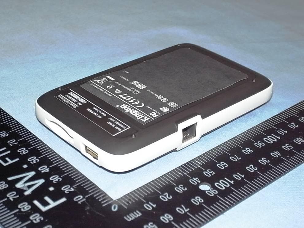
ZME-MLWG2
Apr 09, 2014MOBILELITE WIRELESS G2 (MLWG2)
Equipment Class
DTS - Digital Transmission System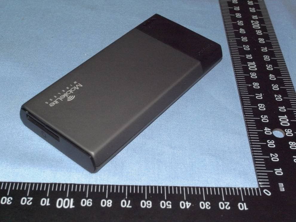
ZME-MLW221
Feb 06, 2013MOBILELITE WIRELESS (MLW221)
Equipment Class
DTS - Digital Transmission System