ZNFK300AMPortable Handset
LG Electronics USA, Inc.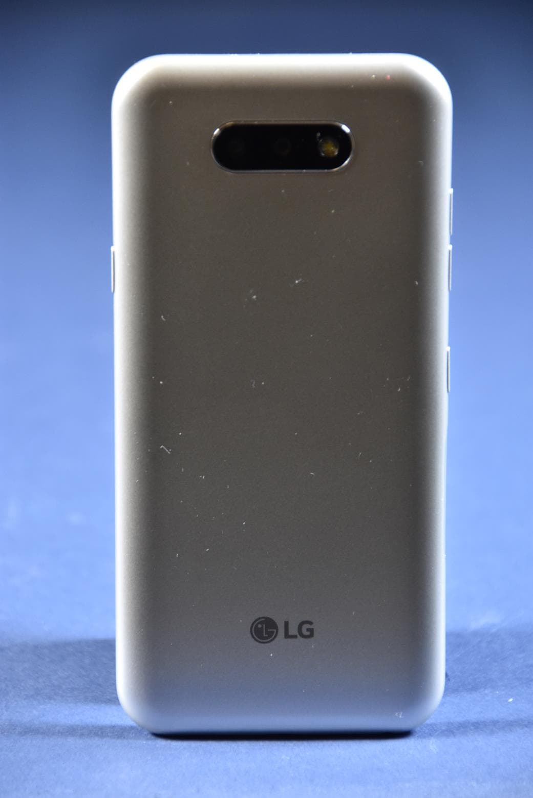
Click to zoom
Application Details
- Equipment Class
- JBP - Part 15 Class B Computing Device Peripheral
- Date of Grant
- Mar 08, 2020
- Application Purpose
- Original Equipment
- Date of Application
- Mar 08, 2020
- Equipment Note
- Portable Handset
- Company
- LG Electronics USA, Inc.
- Country
- United States
Documents & Files
Document Text
Text extracted from the exhibit documents filed with the FCC. Open a document above to read the original.
Cover Letter(s)
LG Electronics USA, Inc. 1000 Sylvan Avenue Englewood Cliffs, NJ 07632 Date: February 20, 2020 Federal Communications Commission Equipment Approval Services 7435 Oakland Mills Road Columbia, MD 21046 RE: Request of Confidentiality for FCC ID: ZNFK300AM Equipment Class: JBP: Part 15 Class B Computing Device Peripheral To whom it may concern: Pursuant to Sections 0.457 and 0.459 of the Commission’s Rules (CFR 47), and Section 552 (b) (4) of the Freedom of Information Act, LG Electronics USA, Inc. hereby requests confidentiality and treatment of certain information accompanying this application. The materials contain trade secrets and proprietary information not customarily released to the public. The public disclosure of these matters might be harmful to the applicant and provide unjustified benefits to its competitors. We are also hereby request Short-Term Confidentiality for 180 days after the grant as outlined in Public Notice DA 04-1705. This provision will give LG Electronics USA, Inc. temporary confidentiality of commercially sensitive information prior to product release. The requested Permanent and Temporary Confidential exhibits are listed as follows: PERMANENT AND SHORT-TERM CONFIDENTIAL LIST Exhibit Description PERMANENT 1 Block Diagram 2 Operational Description SHORT-TERM 3 External Photos 4 Internal Photos 5 Test-Setup Photos 6 User’s Manual This applicant understands that pursuant to Rule 0.457, disclosure of this application and all accompanying documentations, where applicable, will not be made public before the date of the grant for this application. Sincerely, Kyung-Su Han Director On behalf of LG Electronics USA, Inc.
External Photos
LG Electronics USA, Inc. FCC ID: ZNFK300AM Model: LM-K300AM External Photos EUT Type: Portable Handset Page 1 of 5 © 2020 PCTEST V 9.0 02/01/2019 E X T E R N A L P H O T O G R A P H S LG Electronics USA, Inc. FCC ID: ZNFK300AM Model: LM-K300AM External Photos EUT Type: Portable Handset Page 2 of 5 © 2020 PCTEST V 9.0 02/01/2019 LG Electronics USA, Inc. FCC ID: ZNFK300AM Model: LM-K300AM External Photos EUT Type: Portable Handset Page 3 of 5 © 2020 PCTEST V 9.0 02/01/2019 LG Electronics USA, Inc. FCC ID: ZNFK300AM Model: LM-K300AM External Photos EUT Type: Portable Handset Page 4 of 5 © 2020 PCTEST V 9.0 02/01/2019 LG Electronics USA, Inc. FCC ID: ZNFK300AM Model: LM-K300AM External Photos EUT Type: Portable Handset Page 5 of 5 © 2020 PCTEST V 9.0 02/01/2019
ID Label/Location Info
Description of E-Label on the ZNFK300AM 1. FCC ID is applied by E-label on device. [Step2] [Step3] FCC ID E-Label display Step1Select Settings Step2Select System Step 3Select Regulatory& safety [Step1] 2. FCC ID is applied on packaging. FCC ID : ZNFK300AM 3. Instruction of E-label on the user manual Description of E-Label on the ZNFK300AM
Internal Photos
LG Electronics USA, Inc. FCC ID: ZNFK300AM Model: LM-K300AM Internal Photos EUT Type: Portable Handset Page 1 of 6 © 2020 PCTEST V 9.0 02/01/2019 I N T E R NA L P H O T O G RAP H S LG Electronics USA, Inc. FCC ID: ZNFK300AM Model: LM-K300AM Internal Photos EUT Type: Portable Handset Page 2 of 6 © 2020 PCTEST V 9.0 02/01/2019 LG Electronics USA, Inc. FCC ID: ZNFK300AM Model: LM-K300AM Internal Photos EUT Type: Portable Handset Page 3 of 6 © 2020 PCTEST V 9.0 02/01/2019 LG Electronics USA, Inc. FCC ID: ZNFK300AM Model: LM-K300AM Internal Photos EUT Type: Portable Handset Page 4 of 6 © 2020 PCTEST V 9.0 02/01/2019 LG Electronics USA, Inc. FCC ID: ZNFK300AM Model: LM-K300AM Internal Photos EUT Type: Portable Handset Page 5 of 6 © 2020 PCTEST V 9.0 02/01/2019 LG Electronics USA, Inc. FCC ID: ZNFK300AM Model: LM-K300AM Internal Photos EUT Type: Portable Handset Page 6 of 6 © 2020 PCTEST V 9.0 02/01/2019
Test Report
EMI Test for FCC Certification of LM-K300AM Model APPLICANT LG Electronics USA, Inc. REPORT NO. HCT-EM-2002-FC008 DATE OF ISSUE February 18, 2020 The revision history for this test report is shown in table. The device bearing the trade name and model specified above, has been shown to comply with the applicable technical standards as indicated in the measurement report and was tested in accordance with the measurement procedures specified in ANSI C63.4-2014. (See Test Report if any modifications were made for compliance) I attest to the accuracy of data. All measurements reported herein were performed by me or were made under my supervision and are correct to the best of my knowledge and belief. I assume full responsibility for the completeness of these measurements and vouch for the qualifications of all persons taking them. HCT certifies that no party to application has been denial the FCC benefits pursuant to Section 5301 of the Anti- Drug Abuse Act of 1988, 21 U.S.C 862 This Test Report is not related to the accredited test result by KOLAS (Korea Laboratory Accreditation Scheme) / A2LA (American Association for Laboratory Accreditation), which signed the ILAC-MRA. 1. GENERAL INFORMATION 5 1.1 Description of EUT 5 1.2 Tested System Details 6 1.3 Cable Description 7 1.4 Noise Suppression Parts on Cable. (I/O Cable) 7 1.5 Test Facility 8 1.6 Calibration of Measuring Instrument 8 1.7 Measurement Uncertainty 8 2. DESCRIPTION OF TEST 9 2.1 Measurement of Conducted Emission 9 2.2 Measurement of Radiated Emission 10 2.3 Configuration of Tested System 11 3. PRELIMINARY TEST 12 3.1 Conducted Emission 12 3.2 Radiated Emission 12 4. CONDUCTED EMISSION AND RADIATED EMISSION TEST SUMMARY 13 4.1 Conducted Emission 13 4.2 Radiated Emission Below 1 GHz 20 4.3 Radiated Emission Above 1 GHz 22 5. CONCLUSION 25 6. APPENDIX A. TEST SETUP PHOTO 26 All equipment descriptions used in the tested system (including inserted cards) are: Device Type Model Name Serial Number Manufacturer Product Name Port Power Cord Shielded (Y/N) I/O Cable Shielded (Y/N) Length (m) EUT Notebook PC Gateway NOTE. The marked “(D)” means the data cable and “(P)” means the power cable. Product Name Port Ferrite Bead (Y/N) Location Metal Hood (Y/N) Location EUT Notebook PC Test site is located at 74, Seoicheon-ro 578beon-gil, Majang-myeon, Icheon-si, Gyeonggi-do, South Korea. Those measurement facilities are constructed in conformance with the requirements of ANSI C63.4-2014. The Normalized site attenuations (30 MHz to 1 GHz) and Site validation (1 GHz to 18 GHz) were performed in accordance with the standard in ANSI C63.4-2014 Measurement Facilities Designation No. Radiated Field strength measurement facility 3 m Semi Anechoic chamber KR0032 Radiated Field strength measurement facility 10 m Semi Anechoic chamber #1 Radiated Field strength measurement facility 10 m Semi Anechoic chamber #2 The measuring equipment, which was utilized in performing the tests documented herein, has been calibrated in ac cordance with the manufacturers recommendations for utilizing calibration equipment, which is traceable to recognized national standards. Espectially, all antenna for measurement is calibrated in accordance with the requirements of C63.5:2017 The measurement uncertainties shown below were calculated in accordance with the requirements of ANSI C63.4-2014. All measurement uncertainty values are shown with a coverage factor of k = 2 to indicate a 95 % level of confidence. The measurement data shown herein meets or exceeds the U CISPR measurement uncertainty values specified in CISPR 16-4-2 and, thus, can be compared directly to specified limits to determine compliance. The test procedure was in accordance with ANSI C63.4-2014, Clause 7.3 a. The EUT was placed 0.4 meters from the conducting wall of the shielded room with EUT being connected to the power mains through a line impedance stabilization network (LISN). If the EUT is connected to the PC through USB, the AC power-line adapter of the PC is directly connected to a line impedance stabilization network (LISN). Other support units were connected to the power mains through another LISN. The two LISNs provide 50 Ohm/ 50uH of coupling impedance for the measuring instrument. b. Both conducted lines are measured in Quasi-Peak and Average mode, including the worst-case data points for each tested configuration. c. The frequency range from 150 kHz to 30 MHz was searched. Conducted Emission Limits Frequency (MHz) Resolution Bandwidth (kHz) Class A Class B Quasi-Peak (dBμV) Average (dBμV) Quasi-Peak (dBμV) Average (dBμV) 0.15 to 0.5 9 79 66 66 to 56* 56 to 46* 0.5 to 5 9 73 60 56 46 5 to 30 9 73 60 60 50 NOTE. Decreases with the logarithm of the frequency. The test procedure was in accordance with ANSI C63.4-2014, Clause 8.3 a. The EUT was placed on the top of a turn table 0.8 meters above the ground at a semi-anechoic chamber. The table was rotated 360 degrees to determine the position of the highest radiation. b. The EUT was set 3 m away from the interference-receiving antenna, which was mounted on the top of a variable-height antenna tower. c. The antenna height is varied from 1 m to 4 m above the ground to determine the maximum value of the field strength. Both horizontal and vertical polarizations of the antenna are set to make the measurement. d. For each suspected emission, the EUT was arranged to its worst case and then the antenna was tuned to heights from 1 m to 4 m and the turn table was turned from 0 degrees to 360 degrees to find the maximum reading. e. The test-receiver system was set to Quasi-Peak detect function and specified bandwidth with maximum hold mode when the test frequency is below 1 GHz. f. The test-receiver system was set to Peak and Average detect function and specified bandwidth with maximum hold mode when the test frequency is above 1 GHz. g. Place the measurement antenna away from each area of the EUT determined to be a source of emissions at the specified measuremen…
Text truncated - open the document above for the full version.
Test Report
EMI Test for FCC Certification of LM-K300AM Model APPLICANT LG Electronics USA, Inc. REPORT NO. HCT-EM-2002-FC009 DATE OF ISSUE February 18, 2020 The revision history for this test report is shown in table. Revision No. Date of Issue Description The device bearing the trade name and model specified above, has been shown to comply with the applicable technical standards as indicated in the measurement report and was tested in accordance with the measurement procedures specified in ANSI C63.4-2014. (See Test Report if any modifications were made for compliance) I attest to the accuracy of data. All measurements reported herein were performed by me or were made under my supervision and are correct to the best of my knowledge and belief. I assume full responsibility for the completeness of these measurements and vouch for the qualifications of all persons taking them. HCT certifies that no party to application has been denial the FCC benefits pursuant to Section 5301 of the Anti- Drug Abuse Act of 1988, 21 U.S.C 862 This Test Report is not related to the accredited test result by KOLAS(Korea Laboratory Accreditation Scheme) / A2LA(American Association for Laboratory Accreditation), which signed the ILAC-MRA. 1. GENERAL INFORMATION 5 1.1 Description of EUT 5 1.2 Tested System Details 5 1.3 Cable Description 6 1.4 Noise Suppression Parts on Cable. (I/O Cable) 6 1.5 Test Facility 7 1.6 Calibration of Measuring Instrument 7 1.7 Measurement Uncertainty 7 2. DESCRIPTION OF TEST 8 2.1 Measurement of Conducted Emission 8 2.2 Measurement of Radiated Emission 9 2.3 Configuration of Tested System 10 3. PRELIMINARY TEST 11 3.1 Conducted Emission 11 3.2 Radiated Emission 11 4. CONDUCTED EMISSION AND RADIATED EMISSION TEST SUMMARY 12 4.1 Conducted Emission 12 4.2 Radiated Emission Below 1 GHz 19 4.3 Radiated Emission Above 1 GHz 21 5. CONCLUSION 24 6. APPENDIX A. TEST SETUP PHOTO 25 All equipment descriptions used in the tested system (including inserted cards) are: Device Type Model Name Serial Number Manufacturer Product Name Port Power Cord Shielded (Y/N) I/O Cable Shielded (Y/N) Length (m) NOTE. The marked “(D)” means the data cable and “(P)” means the power cable. Product Name Port Ferrite Bead (Y/N) Location Metal Hood (Y/N) Location Test site is located at 74, Seoicheon-ro 578beon-gil, Majang-myeon, Icheon-si, Gyeonggi-do, South Korea. Those measurement facilities are constructed in conformance with the requirements of ANSI C63.4-2014. The Normalized site attenuations (30 MHz to 1 GHz) and Site validation (1 GHz to 18 GHz) were performed in accordance with the standard in ANSI C63.4-2014 Measurement Facilities Designation No. Radiated Field strength measurement facility 3 m Semi Anechoic chamber KR0032 Radiated Field strength measurement facility 10 m Semi Anechoic chamber #1 Radiated Field strength measurement facility 10 m Semi Anechoic chamber #2 The measuring equipment, which was utilized in performing the tests documented herein, has been calibrated in ac cordance with the manufacturers recommendations for utilizing calibration equipment, which is traceable to recognized national standards. Espectially, all antenna for measurement is calibrated in accordance with the requirements of C63.5:2017 The measurement uncertainties shown below were calculated in accordance with the requirements of ANSI C63.4-2014. All measurement uncertainty values are shown with a coverage factor of k = 2 to indicate a 95 % level of confidence. The measurement data shown herein meets or exceeds the U CISPR measurement uncertainty values specified in CISPR 16-4-2 and, thus, can be compared directly to specified limits to determine compliance. Parameter Expanded Uncertainty Conducted Emission (0.15 MHz to 30 MHz) 1.8 dB 3 m Radiated Emissions (30 MHz to 1 GHz) 4.8 dB 3 m Radiated Emissions (1 GHz to 18 GHz) 5.4 dB 3 m Radiated Emissions (18 GHz to 40 GHz) 5.7 dB The test procedure was in accordance with ANSI C63.4-2014, Clause 7.3 a. The EUT was placed 0.4 meters from the conducting wall of the shielded room with EUT being connected to the power mains through a line impedance stabilization network (LISN). If the EUT is connected to the PC through USB, the AC power-line adapter of the PC is directly connected to a line impedance stabilization network (LISN). Other support units were connected to the power mains through another LISN. The two LISNs provide 50 Ohm/ 50uH of coupling impedance for the measuring instrument. b. Both conducted lines are measured in Quasi-Peak and Average mode, including the worst-case data points for each tested configuration. c. The frequency range from 150 kHz to 30 MHz was searched. Conducted Emission Limits Frequency (MHz) Resolution Bandwidth (kHz) Class A Class B Quasi-Peak (dBμV) Average (dBμV) Quasi-Peak (dBμV) Average (dBμV) 0.15 to 0.5 9 79 66 66 to 56* 56 to 46* 0.5 to 5 9 73 60 56 46 5 to 30 9 73 60 60 50 NOTE. Decreases with the logarithm of the frequency. The test procedure was in accordance with ANSI C63.4-2014, Clause 8.3 a. The EUT was placed on the top of a turn table 0.8 meters above the ground at a semi-anechoic chamber. The table was rotated 360 degrees to determine the position of the highest radiation. b. The EUT was set 3 m away from the interference-receiving antenna, which was mounted on the top of a variable-height antenna tower. c. The antenna height is varied from 1 m to 4 m above the ground to determine the maximum value of the field strength. Both horizontal and vertical polarizations of the antenna are set to make the measurement. d. For each suspected emission, the EUT was arranged to its worst case and then the antenna was tuned to heights from 1 m to 4 m and the turn table was turned from 0 degrees to 360 degrees to find the maximum reading. e. The test-receiver system was set to Quasi-Peak detect function and specified bandwidth with maximum hold mode when the test frequency is below 1 GHz. f. The test-receiver system was set to Peak and Average detect functio…
Text truncated - open the document above for the full version.
Test Report
EMI Test for FCC Certification of LM-K300AM Model APPLICANT LG Electronics USA, Inc. REPORT NO. HCT-EM-2002-FC010 DATE OF ISSUE February 18, 2020 The revision history for this test report is shown in table. Revision No. Date of Issue Description The device bearing the trade name and model specified above, has been shown to comply with the applicable technical standards as indicated in the measurement report and was tested in accordance with the measurement procedures specified in ANSI C63.4-2014. (See Test Report if any modifications were made for compliance) I attest to the accuracy of data. All measurements reported herein were performed by me or were made under my supervision and are correct to the best of my knowledge and belief. I assume full responsibility for the completeness of these measurements and vouch for the qualifications of all persons taking them. HCT certifies that no party to application has been denial the FCC benefits pursuant to Section 5301 of the Anti- Drug Abuse Act of 1988, 21 U.S.C 862 This Test Report is not related to the accredited test result by KOLAS(Korea Laboratory Accreditation Scheme) / A2LA(American Association for Laboratory Accreditation), which signed the ILAC-MRA. 1. GENERAL INFORMATION 5 1.1 Description of EUT 5 1.2 Tested System Details 5 1.3 Cable Description 6 1.4 Noise Suppression Parts on Cable. (I/O Cable) 6 1.5 Test Facility 7 1.6 Calibration of Measuring Instrument 7 1.7 Measurement Uncertainty 7 2. DESCRIPTION OF TEST 8 2.1 Measurement of Conducted Emission 8 2.2 Measurement of Radiated Emission 9 2.3 Configuration of Tested System 10 3. PRELIMINARY TEST 11 3.1 Conducted Emission 11 3.2 Radiated Emission 11 4. CONDUCTED EMISSION AND RADIATED EMISSION TEST SUMMARY 12 4.1 Conducted Emission 12 4.2 Radiated Emission Below 1 GHz 19 4.3 Radiated Emission Above 1 GHz 21 5. CONCLUSION 24 6. APPENDIX A. TEST SETUP PHOTO 25 All equipment descriptions used in the tested system (including inserted cards) are: Device Type Model Name Serial Number Manufacturer Product Name Port Power Cord Shielded (Y/N) I/O Cable Shielded (Y/N) Length (m) NOTE. The marked “(D)” means the data cable and “(P)” means the power cable. Product Name Port Ferrite Bead (Y/N) Location Metal Hood (Y/N) Location Test site is located at 74, Seoicheon-ro 578beon-gil, Majang-myeon, Icheon-si, Gyeonggi-do, South Korea. Those measurement facilities are constructed in conformance with the requirements of ANSI C63.4-2014. The Normalized site attenuations (30 MHz to 1 GHz) and Site validation (1 GHz to 18 GHz) were performed in accordance with the standard in ANSI C63.4-2014 Measurement Facilities Designation No. Radiated Field strength measurement facility 3 m Semi Anechoic chamber KR0032 Radiated Field strength measurement facility 10 m Semi Anechoic chamber #1 Radiated Field strength measurement facility 10 m Semi Anechoic chamber #2 The measuring equipment, which was utilized in performing the tests documented herein, has been calibrated in ac cordance with the manufacturers recommendations for utilizing calibration equipment, which is traceable to recognized national standards. Espectially, all antenna for measurement is calibrated in accordance with the requirements of C63.5:2017 The measurement uncertainties shown below were calculated in accordance with the requirements of ANSI C63.4-2014. All measurement uncertainty values are shown with a coverage factor of k = 2 to indicate a 95 % level of confidence. The measurement data shown herein meets or exceeds the U CISPR measurement uncertainty values specified in CISPR 16-4-2 and, thus, can be compared directly to specified limits to determine compliance. Parameter Expanded Uncertainty Conducted Emission (0.15 MHz to 30 MHz) 1.8 dB 3 m Radiated Emissions (30 MHz to 1 GHz) 4.8 dB 3 m Radiated Emissions (1 GHz to 18 GHz) 5.4 dB 3 m Radiated Emissions (18 GHz to 40 GHz) 5.7 dB The test procedure was in accordance with ANSI C63.4-2014, Clause 7.3 a. The EUT was placed 0.4 meters from the conducting wall of the shielded room with EUT being connected to the power mains through a line impedance stabilization network (LISN). If the EUT is connected to the PC through USB, the AC power-line adapter of the PC is directly connected to a line impedance stabilization network (LISN). Other support units were connected to the power mains through another LISN. The two LISNs provide 50 Ohm/ 50uH of coupling impedance for the measuring instrument. b. Both conducted lines are measured in Quasi-Peak and Average mode, including the worst-case data points for each tested configuration. c. The frequency range from 150 kHz to 30 MHz was searched. Conducted Emission Limits Frequency (MHz) Resolution Bandwidth (kHz) Class A Class B Quasi-Peak (dBμV) Average (dBμV) Quasi-Peak (dBμV) Average (dBμV) 0.15 to 0.5 9 79 66 66 to 56* 56 to 46* 0.5 to 5 9 73 60 56 46 5 to 30 9 73 60 60 50 NOTE. Decreases with the logarithm of the frequency. The test procedure was in accordance with ANSI C63.4-2014, Clause 8.3 a. The EUT was placed on the top of a turn table 0.8 meters above the ground at a semi-anechoic chamber. The table was rotated 360 degrees to determine the position of the highest radiation. b. The EUT was set 3 m away from the interference-receiving antenna, which was mounted on the top of a variable-height antenna tower. c. The antenna height is varied from 1 m to 4 m above the ground to determine the maximum value of the field strength. Both horizontal and vertical polarizations of the antenna are set to make the measurement. d. For each suspected emission, the EUT was arranged to its worst case and then the antenna was tuned to heights from 1 m to 4 m and the turn table was turned from 0 degrees to 360 degrees to find the maximum reading. e. The test-receiver system was set to Quasi-Peak detect function and specified bandwidth with maximum hold mode when the test frequency is below 1 GHz. f. The test-receiver system was set to Peak and Average detect functio…
Text truncated - open the document above for the full version.
Test Report
EMI Test for FCC Certification of LM-K300AM Model APPLICANT LG Electronics USA, Inc. REPORT NO. HCT-EM-2002-FC011 DATE OF ISSUE February 18, 2020 The revision history for this test report is shown in table. Revision No. Date of Issue Description The device bearing the trade name and model specified above, has been shown to comply with the applicable technical standards as indicated in the measurement report and was tested in accordance with the measurement procedures specified in ANSI C63.4-2014. (See Test Report if any modifications were made for compliance) I attest to the accuracy of data. All measurements reported herein were performed by me or were made under my supervision and are correct to the best of my knowledge and belief. I assume full responsibility for the completeness of these measurements and vouch for the qualifications of all persons taking them. HCT certifies that no party to application has been denial the FCC benefits pursuant to Section 5301 of the Anti- Drug Abuse Act of 1988, 21 U.S.C 862 This Test Report is not related to the accredited test result by KOLAS(Korea Laboratory Accreditation Scheme) / A2LA(American Association for Laboratory Accreditation), which signed the ILAC-MRA. 1. GENERAL INFORMATION 5 1.1 Description of EUT 5 1.2 Tested System Details 5 1.3 Cable Description 6 1.4 Noise Suppression Parts on Cable. (I/O Cable) 6 1.5 Test Facility 7 1.6 Calibration of Measuring Instrument 7 1.7 Measurement Uncertainty 7 2. DESCRIPTION OF TEST 8 2.1 Measurement of Conducted Emission 8 2.2 Measurement of Radiated Emission 9 2.3 Configuration of Tested System 10 3. PRELIMINARY TEST 11 3.1 Conducted Emission 11 3.2 Radiated Emission 11 4. CONDUCTED EMISSION AND RADIATED EMISSION TEST SUMMARY 12 4.1 Conducted Emission 12 4.2 Radiated Emission Below 1 GHz 19 4.3 Radiated Emission Above 1 GHz 21 5. CONCLUSION 24 6. APPENDIX A. TEST SETUP PHOTO 25 All equipment descriptions used in the tested system (including inserted cards) are: Device Type Model Name Serial Number Manufacturer Product Name Port Power Cord Shielded (Y/N) I/O Cable Shielded (Y/N) Length (m) NOTE. The marked “(D)” means the data cable and “(P)” means the power cable. Product Name Port Ferrite Bead (Y/N) Location Metal Hood (Y/N) Location Test site is located at 74, Seoicheon-ro 578beon-gil, Majang-myeon, Icheon-si, Gyeonggi-do, South Korea. Those measurement facilities are constructed in conformance with the requirements of ANSI C63.4-2014. The Normalized site attenuations (30 MHz to 1 GHz) and Site validation (1 GHz to 18 GHz) were performed in accordance with the standard in ANSI C63.4-2014 Measurement Facilities Designation No. Radiated Field strength measurement facility 3 m Semi Anechoic chamber KR0032 Radiated Field strength measurement facility 10 m Semi Anechoic chamber #1 Radiated Field strength measurement facility 10 m Semi Anechoic chamber #2 The measuring equipment, which was utilized in performing the tests documented herein, has been calibrated in ac cordance with the manufacturers recommendations for utilizing calibration equipment, which is traceable to recognized national standards. Espectially, all antenna for measurement is calibrated in accordance with the requirements of C63.5:2017 The measurement uncertainties shown below were calculated in accordance with the requirements of ANSI C63.4-2014. All measurement uncertainty values are shown with a coverage factor of k = 2 to indicate a 95 % level of confidence. The measurement data shown herein meets or exceeds the U CISPR measurement uncertainty values specified in CISPR 16-4-2 and, thus, can be compared directly to specified limits to determine compliance. Parameter Expanded Uncertainty Conducted Emission (0.15 MHz to 30 MHz) 1.8 dB 3 m Radiated Emissions (30 MHz to 1 GHz) 4.8 dB 3 m Radiated Emissions (1 GHz to 18 GHz) 5.4 dB 3 m Radiated Emissions (18 GHz to 40 GHz) 5.7 dB The test procedure was in accordance with ANSI C63.4-2014, Clause 7.3 a. The EUT was placed 0.4 meters from the conducting wall of the shielded room with EUT being connected to the power mains through a line impedance stabilization network (LISN). If the EUT is connected to the PC through USB, the AC power-line adapter of the PC is directly connected to a line impedance stabilization network (LISN). Other support units were connected to the power mains through another LISN. The two LISNs provide 50 Ohm/ 50uH of coupling impedance for the measuring instrument. b. Both conducted lines are measured in Quasi-Peak and Average mode, including the worst-case data points for each tested configuration. c. The frequency range from 150 kHz to 30 MHz was searched. Conducted Emission Limits Frequency (MHz) Resolution Bandwidth (kHz) Class A Class B Quasi-Peak (dBμV) Average (dBμV) Quasi-Peak (dBμV) Average (dBμV) 0.15 to 0.5 9 79 66 66 to 56* 56 to 46* 0.5 to 5 9 73 60 56 46 5 to 30 9 73 60 60 50 NOTE. Decreases with the logarithm of the frequency. The test procedure was in accordance with ANSI C63.4-2014, Clause 8.3 a. The EUT was placed on the top of a turn table 0.8 meters above the ground at a semi-anechoic chamber. The table was rotated 360 degrees to determine the position of the highest radiation. b. The EUT was set 3 m away from the interference-receiving antenna, which was mounted on the top of a variable-height antenna tower. c. The antenna height is varied from 1 m to 4 m above the ground to determine the maximum value of the field strength. Both horizontal and vertical polarizations of the antenna are set to make the measurement. d. For each suspected emission, the EUT was arranged to its worst case and then the antenna was tuned to heights from 1 m to 4 m and the turn table was turned from 0 degrees to 360 degrees to find the maximum reading. e. The test-receiver system was set to Quasi-Peak detect function and specified bandwidth with maximum hold mode when the test frequency is below 1 GHz. f. The test-receiver system was set to Peak and Average detect functio…
Text truncated - open the document above for the full version.
Test Setup Photos
The revision history for this document is shown in table.
Test Setup Photos
The revision history for this document is shown in table.
Test Setup Photos
The revision history for this document is shown in table.
Contact Information
Applicant
David Kim(Team leader, LGEUS NA Policy & Regulatory Affairs)
Technical Contact
PCTEST Engineering Laboratory, LLCRandy Ortanez
[email protected]410-290-6652
7185 Oakland Mills Road · Columbia, Maryland · United States
Test Firm
HCT Co., Ltd.Lee Yoon-Jung
Technical Specifications
| # | Rule Parts | Frequency Range | Power Output |
|---|---|---|---|
| 1 | 15B | - | - |
Other Applications from LG Electronics USA, Inc.

ZNFTONET80S
Nov 13, 2023Bluetooth Earbuds
Equipment Class
DTS - Digital Transmission System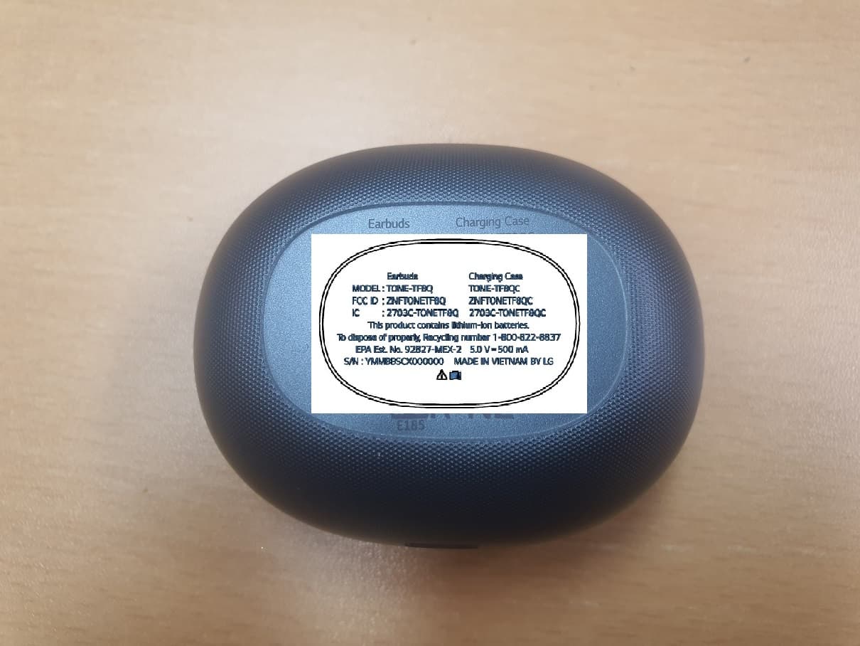
ZNFTONETF8QC
Jun 21, 2022Bluetooth Earbud (Cradle)
Equipment Class
JBP - Part 15 Class B Computing Device Peripheral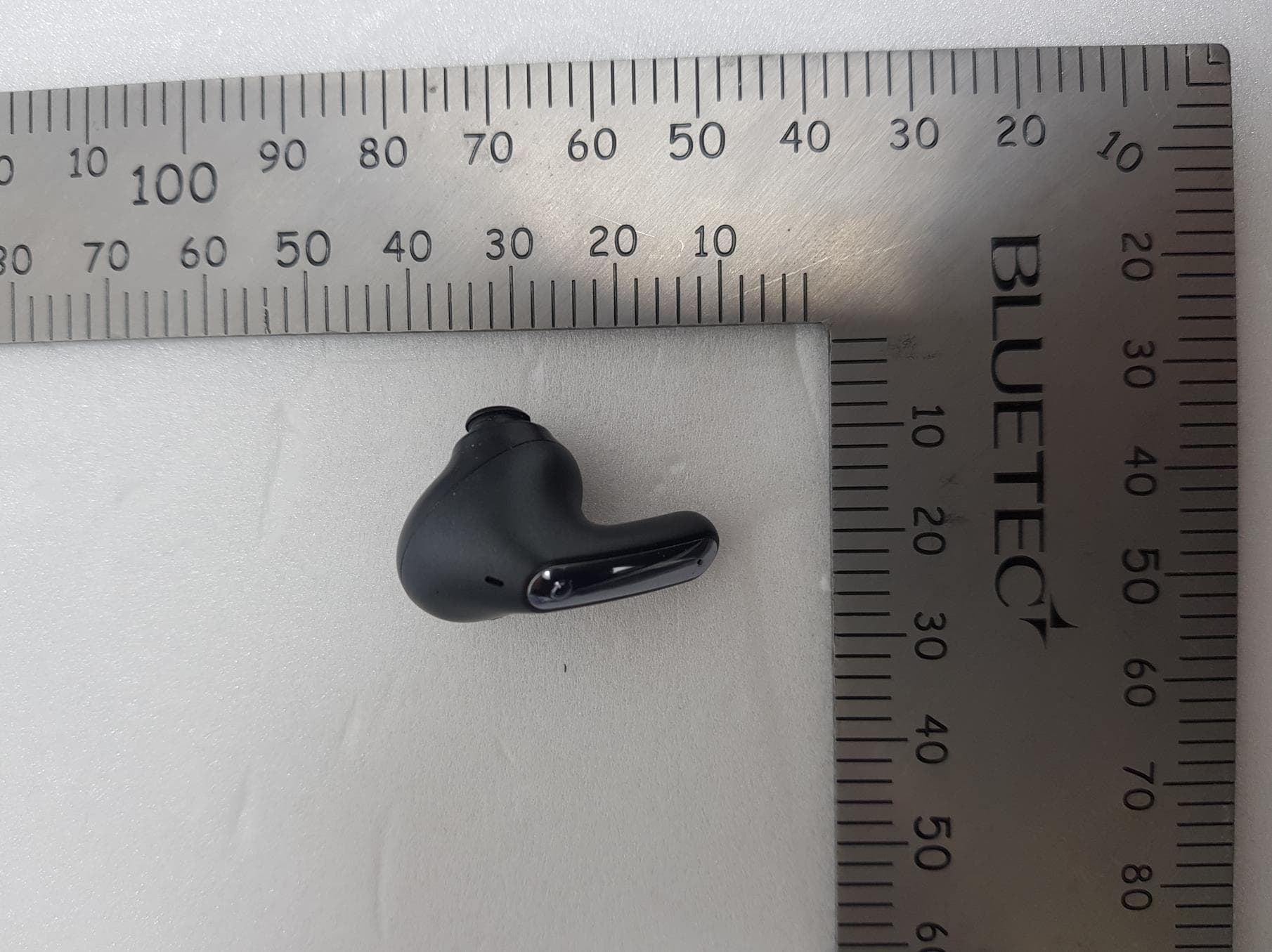
ZNFTONEFP8
May 30, 2021Bluetooth Earbud
Equipment Class
DTS - Digital Transmission System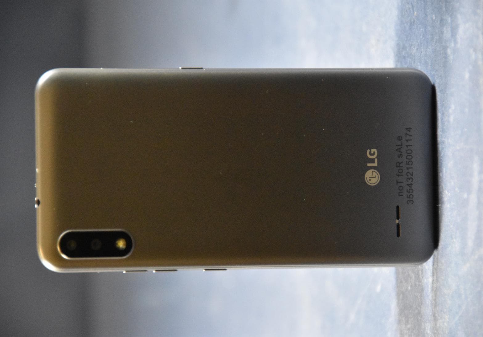
ZNFK200AM
Feb 18, 2021Portable Handset
Equipment Class
DSS - Part 15 Spread Spectrum Transmitter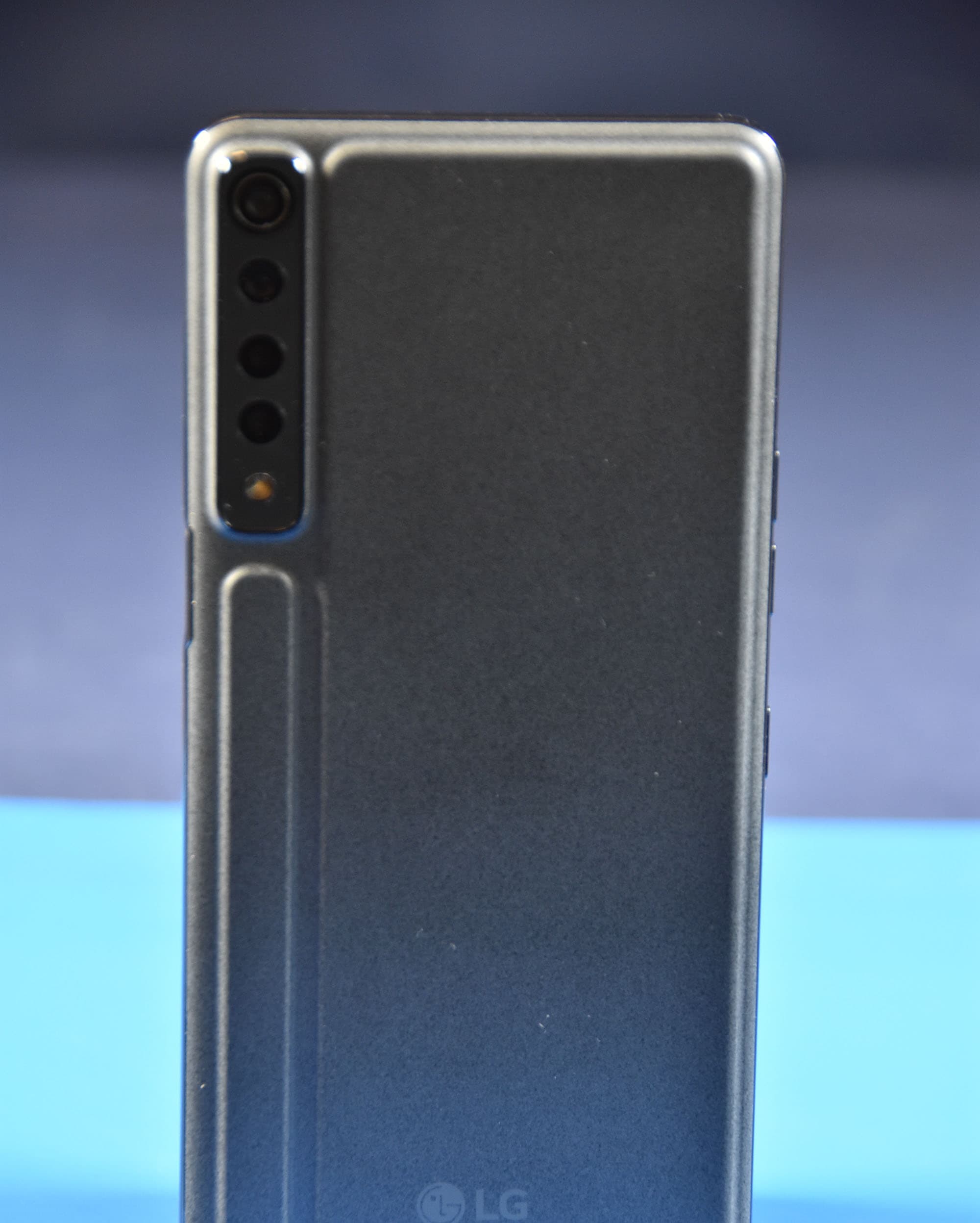
ZNFK735MM
Feb 10, 2021Portable Handset
Equipment Class
NII - Unlicensed National Information Infrastructure TX