ZNK3019-ARFID Tag Reader
Fotorama (Hong Kong) Limited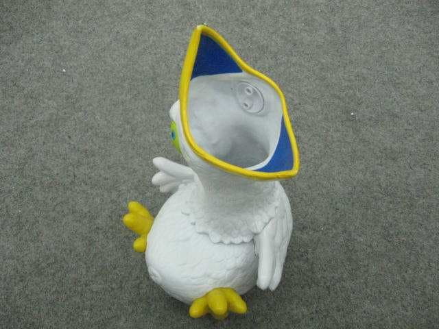
Click to zoom
Application Details
- Equipment Class
- DXX - Part 15 Low Power Communication Device Transmitter
- Date of Grant
- Jun 20, 2012
- Application Purpose
- Original Equipment
- Date of Application
- Jun 20, 2012
- Equipment Note
- RFID Tag Reader
- Frequency Range
- 13.56000000 - 13.56000000
- Company
- Fotorama (Hong Kong) Limited
- Country
- Hong Kong
Documents & Files
Document Text
Text extracted from the exhibit documents filed with the FCC. Open a document above to read the original.
Users Manual
Warning: Changes or modifications to this unit not expressly approved by the party responsible for compliance could void the user’s authority to operate the equipment. NOTE: This equipment has been tested and found to comply with the limits for a Class B digital device, pursuant to Part 15 of the FCC Rules. These limits are designed to provide reasonable protection against harmful interference in a residential installation. This equipment generates, uses and can radiate radio frequency energy and, if not installed and used in accordance with the instructions, may cause harmful interference to radio communications. However, there is no guarantee that interference will not occur in a particular installation. If this equipment does cause harmful interference to radio or television reception, which can be determined by turning the equipment off and on, the user is encouraged to try to correct the interference by one or more of the following measures: Reorient or relocate the receiving antenna. Increase the separation between the equipment and receiver. Connect the equipment into an outlet on a circuit different from that to which the receiver is connected. Consult the dealer or an experienced radio/TV technician for help. This device complies with Part 15 of the FCC Rules. Operation is subject to the following two conditions: (1) this device may not cause harmful interference, and (2) this device must accept any interference received, including interference that may cause undesired operation. FCC Statement Instruction Sheet
External Photos
External Photo Top View of the product Bottom View of the product Side View of the product Side View of the product Battery compartment Battery Cover
ID Label/Location Info
Label location Label format
Internal Photos
Internal Photo Top View of the product (Internal) Bottom View of the product (Internal) Inner Circuit Top View Inner Circuit Bottom View Antenna Antenna MODIFICATIONS 1.) Change the value of C6 to 100p 2.) Move L1 to the DC input port 3.) Add a 56 Ω resistor between the connection of U1 & Us 4.) Add a ferrite bead in the antenna port (ferrite bead specification: 201209-601T) 5.) Add a 2 turns ferrite coil in the antenna input cab le (ferrite coil specification: 12*6*7)
Test Report
BUREAU VERITAS TESTREPORTNo:(5212)130-0205 TESTREPORT To: FolderNo.: E-mail: To: FOTORAMA(HONGKONG)LIMITED Mr.K.S.Chan Attn: Attn: Room7,10/F.,PeninsulaCentre,67Mody Road,TsimshatsuiEast,KLN,HongKong Address: Address: Fax:Fax:35479333 kschanfotorama.com.hkE-mail: Factoryname: Location: Product: SampleNo:(5212)130-0205 TestDate(s): May18,2012 to June4,2012 TestRequested:FCCPart15- 2011 TestMethod: ANSIC63.4- 2009 FCCID:ZNK3019-A Theresultsgivenin thisreportarerelatedto thetestedspecimenof thedescribedelectricalapparatus. AuthorizedSignature: CONCLUSION:Thesubmittedsamplewasfoundto COMPLYwithrequirementofFCCPart15SubpartC. Reviewedb : KeithYeun Date:June14,2012 BUREAUVERITASHONGKONGLIMITED KowloonBayOffice 1/FPacificTradeCentre, 2 KaiHingRoad,KowloonBay, Kowloon,HONGKONG Tel:+85223310888 Fax:+85223310889 www.cps.bureauveritas.com Thisreportis intendedforyourexclusiveuse.An)copyingorrephcanonof thisreportto orforanyotherpersonor entity.oruse ofournameortrademarkISperrruttedonlywithourpnorwnttenpermissionOurreportISlnrutedto thelestsamplesIdentified heremTheresultssetforthm thrsreportarenotnecessarilyindicativeor representativeof thestansncalqualityor characteristicsof thelotfromwhicha lestsamplewastakenoran)similaroridenticalproductunlessspecificallyandexpresslynotedOurreport includesallof thetestsrequestedb)youandtheresultsthereofYoushallhalethmydaysfromreceiptofthisreportto request additionaltestingof thesamplesorto notifyusofan)errorsororrussronsrelanngto ourreport.provided.however.suchnouce shallbeIn wnungandshallspecificallyaddresstheIssueyouWishto raise.A failureto raisesuchIssueWithintheprescnbedtime shallconsrnuteyourunqualifiedacceptanceof thecompletenessof thisreport,thetestsconductedandthecorrectnessof thereport contents Page1 of14 TEST REPORT No: (5212)130-0205 BUREAU VERITAS HONG KONG LIMITED – Kowloon Bay Office 1/F Pacific Trade Centre, 2 Kai Hing Road, Kowloon Bay, Kowloon,HONG KONG Tel: +852 2331 0888 Fax: +852 2331 0889 www.cps.bureauveritas.com This report is intended for your exclusive use. Any copying or replication of this report to or for any other person or entity, or use of our name or trademark, is permitted only with our prior written permission. Our report is limited to the test samples identified herein. The results set forth in this report are not necessarily indicative or representative of the statistical quality or characteristics of the lot from which a test sample was taken or any similar or identical product unless specifically and expressly noted. Our report includes all of the tests requested by you and the results thereof. You shall have thirty days from receipt of this report to request additional testing of the samples or to notify us of any errors or omissions relating to our report, provided, however, such notice shall be in writing and shall specifically address the issue you wish to raise. A failure to raise such issue within the prescribed time shall constitute your unqualified acceptance of the completeness of this report, the tests conducted and the correctness of the report contents. Page 2 of 14 Test Result Summary EMISSION TEST Test requirement: FCC Part 15 - 2011 Test Condition Test Method Test Result Pass Failed Radiated Emission Test, 9kHz to 1GHz ANSI C63.4 Report Revision & Sample Re-submit History: Pass with modification and modification detail as below: 1.) Change the value of C6 to 100p 2.) Move L1 to the DC input port 3.) Add a 56 Ω resistor between the connection of U1 & U2 4.) Add a ferrite bead in the antenna port (ferrite bead specification: 201209-601T) 5.) Add a 2 turns ferrite coil in the antenna input cabel (ferrite coil specification: 12*6*7) TEST REPORT No: (5212)130-0205 BUREAU VERITAS HONG KONG LIMITED – Kowloon Bay Office 1/F Pacific Trade Centre, 2 Kai Hing Road, Kowloon Bay, Kowloon,HONG KONG Tel: +852 2331 0888 Fax: +852 2331 0889 www.cps.bureauveritas.com This report is intended for your exclusive use. Any copying or replication of this report to or for any other person or entity, or use of our name or trademark, is permitted only with our prior written permission. Our report is limited to the test samples identified herein. The results set forth in this report are not necessarily indicative or representative of the statistical quality or characteristics of the lot from which a test sample was taken or any similar or identical product unless specifically and expressly noted. Our report includes all of the tests requested by you and the results thereof. You shall have thirty days from receipt of this report to request additional testing of the samples or to notify us of any errors or omissions relating to our report, provided, however, such notice shall be in writing and shall specifically address the issue you wish to raise. A failure to raise such issue within the prescribed time shall constitute your unqualified acceptance of the completeness of this report, the tests conducted and the correctness of the report contents. Page 3 of 14 Location of the test laboratory Radiated and Conducted emissions measurements are investigated and taken pursuant to the procedures of ANSI C63.4 – 2009. An Open Area Test Site and Full Anechoic Chamber (FCC Listed Site, Registration No. 642151) are set up for investigation and located at: BUREAU VERITAS HONG KONG LIMITED, EMC CENTRE No. 2106-2107, 21/F., Westin Centre, 26 Hung To Road, Kwun Tong, Kowloon, Hong Kong List of measuring equipment Radiated Emission EQUIPMENT MANUFACTURER MODEL NO. SERIAL NO. CALIBRATION DUE EMI TEST RECEIVER R&S ESCI 100379 18-OCT-2012 LOOP ANTENNA ETS-LINDGREN 6502 00102266 07-AUG-2012 BILOG ANTENNA SCHAFFNER CBL6112D 25229 16-SEP-2012 OPEN AREA TEST SITE BVCPS N/A N/A 07-JUL-2012 ANECHOIC CHAMBER ALBATROSS M-CDC 80374004499B 25-OCT-2012 COAXIAL CABLE SUHNER N/A N/A 10-NOV-2012 Frequency error and Frequency drift, Modulation bandwidth, Frequency stability EQUIPMENT MANUFACTURER MODEL NO. SERIAL NO. CALIBRATION DUE EMI TEST RECEIVER ROHDE & SCHWARZ ESCI 1…
Text truncated - open the document above for the full version.
Test Setup Photos
Test Set Up Photo
Contact Information
Applicant
Kin Shu Chan(QA & Engineering Manager)
Test Firm
Bureau Veritas Hong Kong LimitedSteven Tsang
[email protected]85223310728
Technical Specifications
| # | Rule Parts | Frequency Range | Power Output |
|---|---|---|---|
| 1 | 15C | 13.56 MHz - 13.56 MHz | - |
Other Applications from Fotorama (Hong Kong) Limited
ZNK3085E
Jun 14, 2022Tap It
Equipment Class
DXX - Part 15 Low Power Communication Device Transmitter
ZNK3086C
May 07, 2022Shadow Fighter
Equipment Class
DXX - Part 15 Low Power Communication Device Transmitter
ZNK3012-A
Jul 02, 2011Aqua Racer
Equipment Class
DXX - Part 15 Low Power Communication Device Transmitter