ZOHCONFIDANT30GSM/SERIALConverter
Confidant Hawaii, LLC.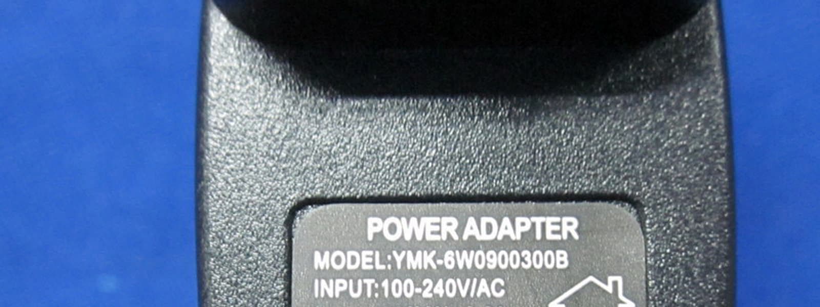
Click to zoom
Application Details
- Equipment Class
- PCB - PCS Licensed Transmitter
- Date of Grant
- Dec 05, 2011
- Application Purpose
- Original Equipment
- Date of Application
- Dec 04, 2011
- Equipment Note
- GSM/SERIALConverter
- Frequency Range
- 1850.20000000 - 1909.80000000
- Company
- Confidant Hawaii, LLC.
- Country
- United States
Documents & Files
Document Text
Text extracted from the exhibit documents filed with the FCC. Open a document above to read the original.
Users Manual
ATTACHMENT 2 User’s Manual Issued by:QAEffective Date:02/23/2011Revision:APage:1of12 820 Mililani Street Suite 600 Honolulu, HI 96813 (W) 808.741.1688 (F) 808.628.6885 www.confidantinc.com 1 Instructions for Use Confidant Connector 3.0 GSM/Serial Converter Description The Confidant Connector (a GSM/Serial Converter), referred to as the Connector, obtains data from personal medical monitoring devices over a serial port and then transmits that data via the Internet over an established GSM/GPRS wireless Network to the Confidant Data Center. Display The display provides the user with the status of the Connector, user choices and displays the results of the process of collecting and storing the readings. The Battery Indicator displays the state of the battery and amount of power to operate the Connector. The Radio Indicator provides an indication of the presence of the GSM network and the relative power ATTACHMENT 2 User’s Manual Issued by:QAEffective Date:02/23/2011Revision:APage:2of12 820 Mililani Street Suite 600 Honolulu, HI 96813 (W) 808.741.1688 (F) 808.628.6885 www.confidantinc.com 2 of the radio signal being received. The Process Indicator is used to inform the user that the Connector is communicating and processing the data with the Data Center. The User Information is broken into four types of information: Initial state and the ability to choose the type of connected personal medical monitoring device. The results of the processing of the data, such as Date/Time with the Blood Glucose reading. The ability to associate additional information with the readings based on the type of device. The display of any error messages. Buttons There are three buttons on the front of the Connector that provide the user interaction with the Connector. POWER –Turns the Connector On and Off A –Toggles information being presented to the user. Such as during the initial use the choices of the types of Devices B –Starts the process of the selected action, such as sending the desired device type to the Data Center ATTACHMENT 2 User’s Manual Issued by:QAEffective Date:02/23/2011Revision:APage:3of12 820 Mililani Street Suite 600 Honolulu, HI 96813 (W) 808.741.1688 (F) 808.628.6885 www.confidantinc.com 3 Installing the Battery The battery chamber is accessed by opening the battery door on the back of the device. Gently slide the door to one side, as indicated by the Open arrow and lift upwards. The inside of the battery compartment is marked for correct battery orientation. The battery must be installed in the correct orientation for the device to operate. The device requires one Li-ion battery (Nokia BL-5C or equivalent). Recharging the Battery The battery is recharged by using the provided 120v AC Charging unit. Plug the USB cable into the charging unit and into the Connector. ChargerUSB cable ATTACHMENT 2 User’s Manual Issued by:QAEffective Date:02/23/2011Revision:APage:4of12 820 Mililani Street Suite 600 Honolulu, HI 96813 (W) 808.741.1688 (F) 808.628.6885 www.confidantinc.com 4 Plugging in the Data Cable Two Data Cables with different sized Plugs are provided; one small (2.5mm) and one large (3.5mm). This is to accommodate a range of monitoring devices with different Socket sizes. Note that either cable can be connected to the Connector using the corresponding Socket. Questions to determine which cable to be used contact Technical support for assistance. 3.5 mm Connector2.5 mm Connector To monitoring deviceTo monitoring device Starting the Connector The Connector is started by pressing and releasing the POWERbutton. The display will light all items, clear the screen and then will display the Battery and Radio Indicators. The personal medical monitoring device selection will be displayed and await the user selecting the default device or toggling through the devices. If the device is idle for 45 seconds it automatically shuts off to conserve battery life. ATTACHMENT 2 User’s Manual Issued by:QAEffective Date:02/23/2011Revision:APage:5of12 820 Mililani Street Suite 600 Honolulu, HI 96813 (W) 808.741.1688 (F) 808.628.6885 www.confidantinc.com 5 Note: The Connector will shut off after 45 seconds of its initial start up unless communications are initiated. Pushing the POWER button repeatedly will turn the Connector ON and OFF and will not improve the performance. Restarting the Connector In the event that problems develop with communication, the Connector can be restarted by pressing the POWER button, to turn the device off and pressing the button a second time to power it on. This restarts the Connector. Process Indicator The Process Indicator cycles through the arrows of the display while communications and processing is taking place. Once processing is completed, the arrows turn off, and the results of the processing and communications are displayed in the User Information area. Error Messages Error Messages are displayed in the User Information area, when they occur. Err01 –Indicates that there was a problem with the Internet connection to the Data Center or the Data Center could not process the information. Corrective action is to retry the process again. Err02 –Indicates that the Connector could not communicate with the personal medical monitoring device. Ensure that the cable is connected properly and is seated securely to the device and the Connector. Retry the process, with the correct device type. Err03 –Indicates there is a problem with the radio signal or the carrier. Contact Technical support for assistance. ATTACHMENT 2 User’s Manual Issued by:QAEffective Date:02/23/2011Revision:APage:6of12 820 Mililani Street Suite 600 Honolulu, HI 96813 (W) 808.741.1688 (F) 808.628.6885 www.confidantinc.com 6 Err04 –Indicates that the battery charger is not charging the battery. Contact Technical support for assistance. Err05 –Indicates that the battery does not have enough of a charge to power the radio successfully. Plug in the charger and charge the battery for two hours. If the problem continues, c…
Text truncated - open the document above for the full version.
Cover Letter(s)
820 Mililani Street Suite 600 Honolulu, HI 96813 (W) 808.741.1688 (F) 808.628.6885 www.confidantinc.com Date: November 15, 2011 American Telecommunication Certification Body, Inc. 6731 Whittier Avenue Suite C110 McLean, VA 22101 To Whom It May Concern: We certify that function of USB port is for battery charging only. Thank you, By:________________________________ John Cheung______ (Signature 1 )(Print name) Title: ______Vice President__________ On behalf of: ________Confidant Hawaii, LLC_________________ (Company Name) Telephone:_808-628-7396_______________________________
Cover Letter(s)
820 Mililani Street Suite 600 Honolulu, HI 96813 (W) 808.741.1688 (F) 808.628.6885 www.confidantinc.com Authority to Act as Agent Date: March 12, 2011 American Certification Body, Inc. 6731 Whittier Avenue Suite C110 McLean, VA 22101 To Whom It May Concern: EEPC Services Limitedis authorized to act on our behalf, until otherwise notified, for applications to American Certification Body, Inc. (ACB). We certify that we are not subject to denial of federal benefits, that includes FCC benefits, pursuant to Section 5301 of the Anti-Drug Abuse Act of 1988, 21 U.S.C. 862. Further, no party, as defined in 47 CFR 1.2002 (b),to the application is subject to denial of federal benefits, that includes FCC benefits. Thank you, Agency Agreement Expiration Date: _____(Typically 8 – 12 months)_____ By:______________________________John Cheung____________ (Signature 1 )(Print name) Title:__Vice President On behalf of: ______Confidant Hawaii, Inc___________ (Company Name) Telephone:_____808-628-7396___________________ 1 -Must be signed by applicant contact given for applicant on the FCC site, or by the authorized agent if an appropriate authorized agent letter has been provided. Letters should be placed on appropriate letterhead. 820 Mililani Street Suite 600 Honolulu, HI 96813 (W) 808.741.1688 (F) 808.628.6885 www.confidantinc.com Request for Confidentiality Date: ________ Subject: Confidentiality Request for: ______ZOHCONFIDANT30______ Pursuant to FCC 47 CRF 0.457(d) and 0.459 and IC RSP-100, Section 10, the applicant requests that a part of the subject FCC application be held confidential. Type of Confidentiality RequestedExhibit Short TermPermanentBlock Diagrams Short TermExternal Photos Short TermPermanent* 2 Internal Photos Short TermPermanentOperation Description/Theory of Operation Short TermPermanentParts List & Placement/BOM Short TermPermanentTune-Up Procedure Short TermPermanentSchematics Short TermTest Setup Photos Short TermPermanent*User’s Manual *Note: ______(Insert Explanation as Necessary)______ Confidant Hawaii, Inchas spent substantial effort in developing this product and it is one of the first of its kind in industry. Having the subject information easily available to "competition" would negate the advantage they have achieved by developing this product. Not protecting the details of the design will result in financial hardship. Permanent Confidentiality: The applicant requests the exhibits listed above as permanently confidential be permanently withheld from public review due to materials that contain trade secrets and proprietary information not customarily released to the public. Short-Term Confidentiality: The applicant requests the exhibits selected above as short term confidential be withheld from public view for a period of 90 days from the date of the Grant of Equipment Authorization and prior to marketing. This is to avoid premature release of sensitive information prior to marketing or release of the product to the public. Applicant is also aware that they are responsible to notify ACB in the event information regarding the product or the product is made available to the public. ACB will then release the documents listed above for public disclosure pursuant to FCC Public Notice DA 04-1705. NOTE for Industry Canada Applications: The applicant understands that until such time that IC distinguishes between Short Term and Permanent Confidentiality, either type of marked exhibit above will simply be marked Confidential when submitted to IC. Sincerely, By:______________________________John Cheung____________________ (Signature/Title 3 )(Print name) 2 - The asterisked items (*) require further justification before permanent confidentiality will be allowed. These also currently require review by the FCC under their Permit-But-Ask policy before the grant is issued and can delay completion of an application. Further justification should be added to the note above. One such example for a potted device would be: “The EUT is FULLY potted using a non-removable epoxy based material. Removal of potting material causes irreparable damage to internal circuitry. See photographs exhibits that outline the device before and after potting.” 3 -Must be signed by applicant contact given for applicant on the FCC site, or by the authorized agent if an appropriate authorized agent letter has been provided. Letters should be placed on appropriate letterhead.
External Photos
External Photos (FCC ID: ZOHCONFIDANT30)
ID Label/Location Info
FCC ID:ZOHCONFIDANT30 Label Location: Label Template: Confidant 3.0 FDAKO72698 FCC ID:ZOHCONFIDANT30
Internal Photos
Internal Photos (FCC ID: ZOHCONFIDANT30)
RF Exposure Info
R AUDIX Technology (Shenzhen) Co., Ltd. Audix Technology (Shenzhen) Co., ltd.. Report No. ACS-SF11008 Page 1 of 111 SAR TEST REPORT for Confidant Hawaii, LLC. GSM/SERIALConverter Model No.: Confidant 3.0 FCC ID: ZOHCONFIDANT30 Prepared for : Confidant Hawaii, LLC. 820 Mililani Street, Suite 600, Honolulu, Hawaii, US Prepared By : Audix Technology (Shenzhen) Co., Ltd. No. 6, Ke Feng Rd., 52 Block, Shenzhen Science & Industrial Park, Nantou, Shenzhen, Guangdong, China Tel: (0755) 26639496 Fax: (0755) 26632877 Report Number : ACS-SF11008 Date of Test : Oct.16~Nov.21, 2011 Date of Report : Nov.23, 2011 R AUDIX Technology (Shenzhen) Co., Ltd. Audix Technology (Shenzhen) Co., ltd.. Report No. ACS-SF11008 Page 2 of 111 TABLE OF CONTENTS Description Page Test Report Verification...........................................................................3 1. GENERAL INFORMATION...................................................................................................... 4 1.1. Description of Device (EUT) ............................................................................................................ 4 1.2. Information Battery of EUT.............................................................................................................. 5 1.3. The Maximum SAR Level ................................................................................................................ 5 1.4. The Maximum Conducted Power Level ........................................................................................... 5 2. OPERATIONAL CONDITIONS................................................................................................ 6 2.1. General Description of Test Configuration.......................................................................................6 2.2. GSM Test Configuration................................................................................................................... 6 2.3. Block Diagram of connection between EUT and Base Station Simulators ...................................... 7 2.4. Test Equipment ................................................................................................................................. 7 2.5. Measurement Uncertainty ................................................................................................................. 7 2.6. Laboratory Environment ................................................................................................................... 7 3. TEST POSITION ......................................................................................................................... 8 3.1. Test Setup of EUT ............................................................................................................................ 8 4. SPECIFIC ABSORPTION RATE (SAR) .................................................................................. 9 4.1. Specific Absorption Rate SAR Introduction..................................................................................... 9 4.2. Specific Absorption Rate SAR Definition ........................................................................................9 5. SAR MEASUREMENTS SYSTEM CONFIGURATION...................................................... 10 5.1. SAR Measurement Set-up............................................................................................................... 10 5.2. SAM Twin Phantom ....................................................................................................................... 11 5.3. ES3DV3 Isotropic E-Field Probe for Dosimetric Measurements ................................................... 12 5.4. Device Holder for SAM Twin Phantom ......................................................................................... 13 5.5. E-field Probe Calibration ................................................................................................................ 14 5.6. Scanning procedure......................................................................................................................... 15 6. DATA STORAGE AND EVALUATION................................................................................. 17 6.1. Data Storage.................................................................................................................................... 17 6.2. Data Evaluation by SEMCAD ........................................................................................................ 17 7. TISSUE SIMULATING LIQUIDS ........................................................................................... 19 8. SYSTEM CHECK ...................................................................................................................... 20 9. TEST RESULTS......................................................................................................................... 21 9.1. Table 10.1 System Check for Body Tissue simulating liquid......................................................... 21 9.2. Table 10.2 Dielectric Performance for Body Tissue simulating liquid........................................... 22 10. TEST RESULTS......................................................................................................................... 23 10.1. Conducted Output Average Power .................................................................................................23 10.2. Table 10.1 System Check for Body Tissue simulating liquid......................................................... 24 10.3. System Check Results ..................................................................................................................... 25 10.4. System Check Results ..................................................................................................................... 27 10.5. System Check Results ........................................................................................................…
Text truncated - open the document above for the full version.
Test Report
R AUDIX Technology (Shenzhen) Co., Ltd. FCC ID:ZOHCONFIDANT30 Audix Technology (Shenzhen) Co., Ltd. Report No. ACS-F11221 FCC PART 15C TEST REPORT FOR CERTIFICATION On Behalf of Confidant Hawaii, LLC. GSM/SERIALConverter Model No.: Confidant 3.0 FCC ID: ZOHCONFIDANT30 Prepared for : Confidant Hawaii, LLC. 820 Mililani Street, Suite 600, Honolulu, Hawaii, US Prepared By : Audix Technology (Shenzhen) Co., Ltd. No. 6, Ke Feng Rd., 52 Block, Shenzhen Science & Industrial Park, Nantou, Shenzhen, Guangdong, China Tel: (0755) 26639496 Report Number : ACS-F11221 Date of Test : Oct.06~08, 2011 Date of Report : Oct.10, 2011 R AUDIX Technology (Shenzhen) Co., Ltd. FCC ID:ZOHCONFIDANT30 Audix Technology (Shenzhen) Co., Ltd. Report No. ACS-F11221 TABLE OF CONTENTS Description Page 1. SUMMARY OF STANDARDS AND RESULTS.......................................................... 1-1 1.1. Description of Standards and Results .................................................................................. 1-1 2. GENERAL INFORMATION ......................................................................................... 2-1 2.1. Description of Device (EUT) ............................................................................................... 2-1 2.2. Block diagram of connection between the EUT and simulators .......................................... 2-1 2.3. Test Facility ......................................................................................................................... 2-2 2.4. Measurement Uncertainty (95% confidence levels, k=2) .................................................... 2-2 3. EFFECTIVE ISOTROPIC RADIATED POWER ...................................................... 3-1 3.1. Test Equipment .................................................................................................................... 3-1 3.1. Limit..................................................................................................................................... 3-2 3.2. Test Procedure: .................................................................................................................... 3-2 3.3. Test Results .......................................................................................................................... 3-3 4. OUT OF BAND EMISSIONS AT ANTENNA TERMINALS AND ........................... 4-1 BAND EDGE ............................................................................................................................... 4-1 4.1. Test Equipment .................................................................................................................... 4-1 4.2. Limit..................................................................................................................................... 4-1 4.3. Test Procedure...................................................................................................................... 4-1 4.4. Test result ............................................................................................................................. 4-1 5. 99% Occupied Bandwidth Test ...................................................................................... 5-1 5.1. Test Equipment .................................................................................................................... 5-1 5.2. Test Procedure...................................................................................................................... 5-1 5.3. Test Results .......................................................................................................................... 5-1 6. RF POWER OUTPUT TEST ......................................................................................... 6-1 6.1. Test Equipment .................................................................................................................... 6-1 6.2. Limit..................................................................................................................................... 6-1 6.3. Test Procedure...................................................................................................................... 6-1 6.4. Test Results .......................................................................................................................... 6-2 7. FIELD STRENGTH OF RADIATED SPURIOUS EMISSIONS ............................... 7-1 7.1. Test Equipment .................................................................................................................... 7-1 7.2. Limit..................................................................................................................................... 7-2 7.3. Test Procedure...................................................................................................................... 7-2 7.4. Test Results .......................................................................................................................... 7-1 8. FREQUENCY STABILITY V.S. TEMPERATURE AND VOLTAGE ..................... 8-1 8.1. Test Equipment .................................................................................................................... 8-1 8.1. Limit..................................................................................................................................... 8-2 8.2. Test procedure:..................................................................................................................... 8-2 9. DEVIATION TO TEST SPECIFICATIONS................................................................ 9-1 10. PHOTOGRAPH OF TEST ........................................................................................... 10-1 11. PHOTOS OF THE EUT................................................................................................ 11-1 R AUDIX Technology (Shenzhen) Co., Ltd. FCC ID:ZOHCONFIDANT30 page Audix Technology (Shenzhen) Co., Ltd. Report No. ACS-F11221 1-1 1. SUM…
Text truncated - open the document above for the full version.
Test Setup Photos
R AUDIX Technology (Shenzhen) Co., Ltd. Audix Technology (Shenzhen) Co., Ltd. Report No. ACS-F11128 page 30 of 41 6. PHOTOGRAPH 6.1. Photos of Power Line Conducted Emission Test Charge Mode R AUDIX Technology (Shenzhen) Co., Ltd. Audix Technology (Shenzhen) Co., Ltd. Report No. ACS-F11128 page 31 of 41 Data Transmitting Mode R AUDIX Technology (Shenzhen) Co., Ltd. Audix Technology (Shenzhen) Co., Ltd. Report No. ACS-F11128 page 32 of 41 6.2. Photos of Radiated Emission Test (In Anechoic Chamber) Charge Mode R AUDIX Technology (Shenzhen) Co., Ltd. Audix Technology (Shenzhen) Co., Ltd. Report No. ACS-F11128 page 33 of 41 R AUDIX Technology (Shenzhen) Co., Ltd. Audix Technology (Shenzhen) Co., Ltd. Report No. ACS-F11128 page 34 of 41 Data Transmitting Mode R AUDIX Technology (Shenzhen) Co., Ltd. Audix Technology (Shenzhen) Co., Ltd. Report No. ACS-F11128 page 35 of 41 (At Anechoic 3m Chamber Test 1GHz –6GHz) R AUDIX Technology (Shenzhen) Co., Ltd. Audix Technology (Shenzhen) Co., Ltd. Report No. ACS-F11128 page 36 of 41 7. PHOTOS OF THE EUT Figure 1 General Appearance of the EUT Figure 2 General Appearance of the EUT R AUDIX Technology (Shenzhen) Co., Ltd. Audix Technology (Shenzhen) Co., Ltd. Report No. ACS-F11128 page 37 of 41 Figure 3 General Appearance of the EUT Figure 4 General Appearance of the EUT R AUDIX Technology (Shenzhen) Co., Ltd. Audix Technology (Shenzhen) Co., Ltd. Report No. ACS-F11128 page 38 of 41 Figure 5 Inside of the EUT Figure 6 Inside of the EUT R AUDIX Technology (Shenzhen) Co., Ltd. Audix Technology (Shenzhen) Co., Ltd. Report No. ACS-F11128 page 39 of 41 Figure 7 Inside of the EUT Figure 8 Component side of the PCB R AUDIX Technology (Shenzhen) Co., Ltd. Audix Technology (Shenzhen) Co., Ltd. Report No. ACS-F11128 page 40 of 41 Figure 9 Component side of the PCB Figure 10 USB Cable R AUDIX Technology (Shenzhen) Co., Ltd. Audix Technology (Shenzhen) Co., Ltd. Report No. ACS-F11128 page 41 of 41 Figure 11 Power Adapter Figure 12 Power Adapter
Test Setup Photos
R AUDIX Technology (Shenzhen) Co., Ltd. FCC ID:ZOHCONFIDANT30 page Audix Technology (Shenzhen) Co., Ltd. Report No. ACS-F11221 10-1 10. PHOTOGRAPH OF TEST R AUDIX Technology (Shenzhen) Co., Ltd. FCC ID:ZOHCONFIDANT30 page Audix Technology (Shenzhen) Co., Ltd. Report No. ACS-F11221 10-2 R AUDIX Technology (Shenzhen) Co., Ltd. FCC ID:ZOHCONFIDANT30 page Audix Technology (Shenzhen) Co., Ltd. Report No. ACS-F11221 10-3
Test Setup Photos
R AUDIX Technology (Shenzhen) Co., Ltd. Audix Technology (Shenzhen) Co., ltd.. Report No. ACS-SF11008 Page 101 of 111 14. PHOTOGRAPHS OF TEST Back Top GPS Antenna R AUDIX Technology (Shenzhen) Co., Ltd. Audix Technology (Shenzhen) Co., ltd.. Report No. ACS-SF11008 Page 102 of 111 Bottom Left GPS Antenna R AUDIX Technology (Shenzhen) Co., Ltd. Audix Technology (Shenzhen) Co., ltd.. Report No. ACS-SF11008 Page 103 of 111 Right Front GPRS Antenna
Contact Information
Applicant
John L Cheung
Technical Contact
Confidant Hawaii, LLC.John L Cheung
[email protected]808-741-1688
820 MililaniStreet, Suite 600 · Honolulu · United States
Non-Technical Contact
Confidant Hawaii, LLC.John L Cheung
[email protected]808-741-1688
Test Firm
Audix Technology (Shenzhen) Co.Smart Tsai
Technical Specifications
| # | Rule Parts | Frequency Range | Power Output | Emission | Tolerance |
|---|---|---|---|---|---|
| 2 | 24E | 1.85 GHz - 1.91 GHz | 1.426 W | 300KGXW | 0.1 ppm |