ZPRM3-UHF-450100W UHF BASE STATION
Raytheon IDS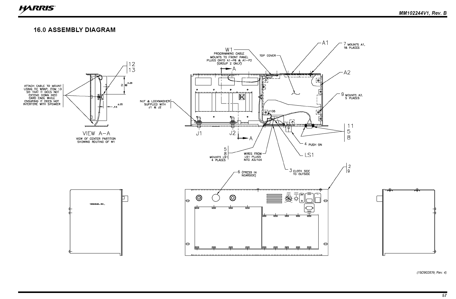
Click to zoom
Application Details
- Equipment Class
- TNB - Licensed Non-Broadcast Station Transmitter
- Date of Grant
- Dec 29, 2011
- Application Purpose
- Original Equipment
- Date of Application
- Dec 29, 2011
- Equipment Note
- 100W UHF BASE STATION
- Frequency Range
- 450.00000000 - 512.00000000
- Company
- Raytheon IDS
- Country
- United States
Documents & Files
Document Text
Text extracted from the exhibit documents filed with the FCC. Open a document above to read the original.
Users Manual
MASTR III Repeater Calibration Procedure 5/16/2011 Raytheon JPS Communications, Inc. 2-1 8/22/2011 1 Repeater Configuration 1.1 Radio Programming The radio should be programmed using the Harris MASTR III Control Shelf Programming application M3.BAT (MS-DOS batch file) using a standard RS232 serial cable connected to the MASTR III Data Port (Left Receiver or Right Receiver) and the host PC. The Bandwidth should be set for 12.5kHz Narrowband operation. Default factory settings are used for all other parameters except as required by the user. 1.1.1 Options Menu F7 The Bandwidth should be set for 12.5kHz Narrowband operation. Enable “Digital Pager” and “P25”. Default factory settings are used for all other parameters except as required by the user. Figure 1-1 Bandwidth Setting 2 Radio Calibration using PCCT Radio calibration requires a Radio Service Test Set with APCO 25 capability. The following example uses an Aeroflex 3920. 2.1.1 Equipment Set Up MASTR III Repeater Calibration Procedure 5/16/2011 Raytheon JPS Communications, Inc. 2-2 8/22/2011 Connect the equipment as shown below: Figure 2-1 Equipment Setup Aeroflex 3920 T/R Radio Under Calibration Tx P25CC PC PCCT Calibration Software CAT 5 50 ohm coax P25CC Radio Interface Cable MASTR III Repeater Calibration Procedure 5/16/2011 Raytheon JPS Communications, Inc. 2-3 8/22/2011 2.1.2 Initial Steps 2.1.2.1 Set the Radio Test Set to analog duplex mode and program to monitor the frequency of the transmitter. 2.1.2.2 Power up the radio and P25net CC. 2.1.2.3 Launch PCCT and connect to the P25net CC channel. 2.1.3 Radio Tx Calibration 2.1.3.1 In PCCT go to the Configure >Tx window and select Analog Sine Wave per Figure 2-2. Preset the Tx Gain and Offset Pots to the values shown. Figure 2-2 Configure Tx Window MASTR III Repeater Calibration Procedure 5/16/2011 Raytheon JPS Communications, Inc. 2-4 8/22/2011 2.1.3.2 Start a Sine Wave test tone in PCCT and adjust the Tx Gain for approximately 2.8kHz as read on the test set deviation meter (Figure 2-3). Adjust the Tx Offset to as necessary to get the correct transmit frequency (minimum offset). The Tx Gain and Offset Pots are interactive so this will require some iteration to get the proper settings. Once you have made coarse adjustments, use the TxVcoGain and TxVcoOffset Pots for finer steps. The TxVcoOffset Pot has 100 step increments; you can interpolate and enter a number in the box to get a finer step if necessary. Figure 2-3 Test Set Oscilloscope: Demodulated Audio MASTR III Repeater Calibration Procedure 5/16/2011 Raytheon JPS Communications, Inc. 2-5 8/22/2011 2.1.3.3 Change the test tone selection on PCCT to Analog Short Square Wave (100Hz) and verify the demodulated audio oscilloscope displays a good approximation of a square wave with generally flat high and low levels (Figure 2-4). A poor square wave indicates the radio needs to be aligned with the factory service software to achieve better DC Balance. Figure 2-4 Test Set Oscilloscope: Short Square Wave MASTR III Repeater Calibration Procedure 5/16/2011 Raytheon JPS Communications, Inc. 2-6 8/22/2011 2.1.3.4 Reconfigure the test set for P25 mode. 2.1.3.5 Start an IMBE test tone using PCCT set to Standard Tone Test Pattern. Figure 2-5 Standard Tone Test Pattern MASTR III Repeater Calibration Procedure 5/16/2011 Raytheon JPS Communications, Inc. 2-7 8/22/2011 2.1.3.6 Listen for a 1200Hz sine wave in the monitor speaker set for demodulated audio. A P25 Handset may also be used for this step if tuned to the proper frequency in conventional P25 mode. 2.1.3.7 Check the Symbol Deviation to verify that it is 1750Hz +/- 75Hz; adjust the TxVcoGain to increase or decrease the deviation if necessary. Also, you may adjust the Frequency Error by trimming the TxVcoOffset if needed. The Constellation and Eye Diagrams are shown for reference. The Modulation Fidelity should be better than 5% (typically<2%; SeeFigure 2-6) . Figure 2-6 Transmitter Performance Screen This completes Transmitter calibration. Unkey the transmitter and install a dummy load on the Tx output in preparation for Receiver calibration 2.2 Rx Calibration Receive calibration adjusts the P25net CC audio input level to match the radio line audio output level and calibrates the P25net CC for the RSSI signal from the receiver. • Rx Gain provides adjustment for the receiver line audio output entering the Channel Card. MASTR III Repeater Calibration Procedure 5/16/2011 Raytheon JPS Communications, Inc. 2-8 8/22/2011 • Rx Offset provides a DC reference level adjustment for the receiver audio. This adjustment allows the output reference DC level from the receiver to be matched by the P25netCC Rx input. • RSSI Gain provides level adjustment for the RSSI input. • RSSI Offset provides a DC reference level adjustment for the RSSI input signal. 2.2.1 Equipment Setup Connect the equipment as shown in Figure 2-7. Figure 2-7 Rx Calibration Set-up Aeroflex 3920 T/R Radio Under Calibration Tx P25CC PC PCCT Calibration Software CAT 5 50 ohm coax Rx 50 ohm dummy load 50 ohm coax P25CC Radio Interface Cable MASTR III Repeater Calibration Procedure 5/16/2011 Raytheon JPS Communications, Inc. 2-9 8/22/2011 2.2.2 Initial Steps 2.2.2.1 Launch PCCT and go to the Configure >Rx and Tx Manual window and set default values for the Rx and RSSI parameters as shown in Figure 2-8. Check the “Enable Editing” boxes for entering parameters. Figure 2-8 Configure Tx and Rx (Manual) Window MASTR III Repeater Calibration Procedure 5/16/2011 Raytheon JPS Communications, Inc. 2-10 8/22/2011 2.2.3 Rx Calibration 2.2.3.1 Go to the Configure > Rx (Automatic) screen. 2.2.3.2 Set the generator to Analog Duplex Mode at the Receiver frequency; set the modulation for a 1200Hz Sine with 2.83kHz deviation. With the generator on and set to -70dBm, Check the Rx beam box and start the oscilloscope on PCCT. 2.2.3.3 Adjust the Rx Offset so the mean of the observed sine wave is centered as close as possible about zero. Adjust the Rx Gain so t…
Text truncated - open the document above for the full version.
Users Manual
System Operator’s User Manual P25net Channel Controller Raytheon Company 5800 Departure Drive Raleigh, NC 27616 24/7 Technical Support For support, call 1-800-498-3137 Email: [email protected] P/N 5060-600200 Revision 1.05 March, 2011 P25net Channel Controller Operations Manual 2 PROPRIETARY STATEMENT This document is copyright © Raytheon 2011. No part of this document may be reproduced in any form, transmitted, or stored in a retrieval system without the prior written consent of Raytheon. This document is classified Commercial in Confidence. Its contents may not be divulged to third parties without the prior written consent of Raytheon. The information contained in this manual is the property of Raytheon and is intended for the purchaser’s use only. NOTICE Raytheon reserves the right to make changes to the equipment and specifications without prior notice. Raytheon Company Phone: (919) 790-1011 Fax: (919) 790-1456 5800 Departure Drive Raleigh, NC 27616 P25net Channel Controller Operations Manual 3 CONTROL AND OWNERSHIP This is a controlled document. Unless stated otherwise, the sole controlled copy of this document resides in the Raytheon document control repository, and other copies in electronic and printed form are uncontrolled. REVISION HISTORY Revision Date Details 1.00 03 Jan. 2008 First Release 1.01 24 Jan 2008 Minor updates & formatting; no technical changes 1.03 08 Oct 2008 Added Specifications and Radio Calibration using PCCT 1.04 22 Jan 2009 “Branding” edits to contents 1.05 28 Mar 2011 New product photos, updated interface specification P25net Channel Controller Operations Manual 4 Table of Contents 1 INTRODUCTION ......................................................................................................................................... 1-1 1.1 Scope .................................................................................................................................................... 1-1 1.2 Description ........................................................................................................................................... 1-1 1.3 Analog Base Radio Requirements ........................................................................................................ 1-2 1.3.1 Duplex Operation ............................................................................................................................ 1-2 1.3.2 Unbalanced Wideband Audio .......................................................................................................... 1-2 1.3.3 PTT/Keyline .................................................................................................................................... 1-2 1.3.4 RSSI ................................................................................................................................................ 1-2 1.3.5 Frequency Stability .......................................................................................................................... 1-3 1.3.6 Narrowband Channel Bandwidth .................................................................................................... 1-3 1.4 Specifications ....................................................................................................................................... 1-3 1.5 Equipment Supplied ............................................................................................................................. 1-4 1.6 Optional Equipment-Not Supplied ....................................................................................................... 1-6 2 INSTALLATION .......................................................................................................................................... 2-1 2.1 General ................................................................................................................................................. 2-1 2.2 Unpacking and Inspection .................................................................................................................... 2-1 2.3 Reshipment of Equipment .................................................................................................................... 2-1 2.4 Installation Overview ........................................................................................................................... 2-2 2.5 Installation Considerations ................................................................................................................... 2-3 2.5.1 Mounting ......................................................................................................................................... 2-3 2.5.2 Cooling ............................................................................................................................................ 2-3 2.5.3 Front Panel Indicators ...................................................................................................................... 2-3 2.5.4 Rear Panel Connectors and Controls ............................................................................................... 2-4 2.6 AC Power Requirements ...................................................................................................................... 2-7 2.7 DC Power Requirements ...................................................................................................................... 2-7 2.8 Network Connection ............................................................................................................................ 2-8 2.9 Radio Interface Connection .................................................................................................................. 2-8 3 RADIO CALIBRATION .............................................................................................................................. 3-1 3.1 Calibration Overview ...........................................................…
Text truncated - open the document above for the full version.
Users Manual
Overview Manual MM102558V1 R1A, Jul/06 MASTR ® III Conventional ADC & P25 Conventional Base Stations MM102558V1 R1A MANUAL REVISION HISTORY REV DATE REASON FOR CHANGE R1A Jul/06 Initial Release. M/A-COM Technical Publications would particularly appreciate feedback on any errors found in this document and suggestions on how the document could be improved. Submit your comments and suggestions to: Wireless Systems Business Unit or fax your comments to: (434) 455-6851 M/A-COM, Inc. Technical Publications or e-mail us at: [email protected] 221 Jefferson Ridge Parkway Lynchburg, VA 24501 ACKNOWLEDGEMENTS This manual covers M/A-COM products manufactured and sold by M/A-COM, Inc. This device made under license under one or more of the following US patents: 4,590,473; 4,636,791; 5,148,482; 5,185,796; 5,271,017; 5,377,229. The voice coding technology embodied in this product is protected by intellectual property rights including patent rights, copyrights, and trade secrets of Digital Voice Systems, Inc. The user of this technology is explicitly prohibited from attempting to decompile, reverse engineer, or disassemble the Object Code, or in any way convert the Object Code into human-readable form. CREDITS MASTR and Voice Guard are registered trademarks of M/A-COM, Inc. GETC, ProVoice and Secur-It are trademarks of M/A-COM, Inc. Microsoft, Windows, and Windows NT are registered trademarks of Microsoft Corporation Pentium is a registered trademark of Intel Corporation. All other brand and product names are registered trademarks, trademarks, or service marks of their respective holders. NOTICE! Repairs to this equipment should be made only by an authorized service technician or facility designated by the supplier. Any repairs, alterations or substitutions of recommended parts made by the user to this equipment not approved by the manufacturer could void the user's authority to operate the equipment in addition to the manufacturer's warranty. This product conforms to the European Union WEEE Directive 2002/96/EC. Do not dispose of this product in a public landfill. Take it to a recycling center at the end of its life. This manual is published by M/A-COM, Inc., without any warranty. Improvements and changes to this manual necessitated by typographical errors, inaccuracies of current information, or improvements to programs and/or equipment, may be made by M/A-COM, Inc., at any time and without notice. Such changes will be incorporated into new editions of this manual. No part of this manual may be reproduced or transmitted in any form or by any means, electronic or mechanical, including photocopying and recording, for any purpose, without the express written permission of M/A-COM, Inc. Copyright© 2006 M/A-COM, Inc. All rights reserved. 2 MM102558V1 R1A TABLE OF CONTENTS Page 1 REGULATORY AND SAFETY INFORMATION.......................................................................... 6 1.1 MAXIMUM PERMISSIBLE EXPOSURE LIMITS ................................................................................. 6 1.2 DETERMINING MPE RADIUS.................................................................................................................. 6 1.3 SAFETY TRAINING INFORMATION .....................................................................................................6 1.4 REGULATORY APPROVALS ................................................................................................................... 7 1.5 SAFETY SYMBOL CONVENTIONS ........................................................................................................ 8 2 PREFACE ............................................................................................................................................ 9 2.1 ABOUT THIS MANUAL ............................................................................................................................. 9 2.2 GLOSSARY OF TERMS ........................................................................................................................... 10 2.3 CUSTOMER SERVICE ............................................................................................................................. 11 2.3.1 Technical Support........................................................................................................................... 11 2.3.2 Customer Resource Center ............................................................................................................. 12 3 SPECIFICATIONS ........................................................................................................................... 13 3.1 CABINET..................................................................................................................................................... 13 3.2 SOURCE POWER DRAIN ........................................................................................................................ 13 3.3 STATION ..................................................................................................................................................... 14 3.4 INTERFACE ............................................................................................................................................... 14 3.5 TRANSMITTER ......................................................................................................................................... 15 3.6 RECEIVER .................................................................................................................................................. 16 3.7 INDIVIDUAL EQUIPMENT WEIGHTS................................................................................................. 18 4 GENERAL INFORMATION ........................................................................................................... 19 4.1 REFERENCE MANUALS .....................................................................................................…
Text truncated - open the document above for the full version.
Cover Letter(s)
Wednesday, March 26, 2003 Federal Communications Commission Authorization and Evaluation Division Confidentiality Request regarding application for certification of FCC ID: ZPRM3-UHF-450 Pursuant to Sections 0.457 and 0.459 of the Commission’s Rules, we hereby request confidential treatment of information accompanying this application as outlined below: Exhibit Type File Name Operational Descriptions Descriptions.pdf Parts Lists Parts List.pdf Schematics Schematics.pdf Tuning procedures Tuning procedure.pdf Block Diagrams Block diagram.pdf The above materials contain trade secrets and proprietary information not customarily released to the public. The public disclosure of these materials may be harmful to the applicant and provide unjustified benefits to its competitors. Sincerely, Michael C. Beck
External Photos
Power Amplifier (450-512 MHz) front Power Amplifier (450-512 MHz) back
External Photos
Exterior Photographs of Mastr III Base Station Radio Figure 1 Mastr3 Front View Figure 3 Mastr3 Rear View Figure 2 Mastr3 Top View AC/DC Power Supply Model: SP593-1A Rev X02 Input: 100/240V 47-63 Hz S/N: QG12659 Board: 112959 X02 Figure 1: AC/DC Power Supply Front Cover Figure 2: AC/DC Power Supply Top Cover Figure 3: AC/DC Power Supply Back Connectors SitePro: 428932 Macom 9851167 Figure 6: SitePro Front Cover Figure 7: SitePro Top Cover Figure 8: SitePro Back Connectors Figure 9: SitePro Bottom Cover
External Photos
Page 2 Figure 1 - Rx IF overall
External Photos
Rx synthesizer (400-430 MHz and 450-470 MHz) with shield Rx synthesizer (400-430 MHz and 450-470 MHz) with secondary shield Rx synthesizer (425-450 MHz and 470-512 MHz) with shield
External Photos
Figure 1 P25netCC Front View Figure 2 P25netCC Rear View
ID Label/Location Info
FCC ID FCC ID Label Location 0.75in FCC ID: ZPRM3-UHF-450 IC: 9749A-M3UHF450 Model: P25net M3UHF450 Raytheon JPS Communications 2.0 in
Internal Photos
Power Amplifier (450-512 MHz) internal picture 1 Power Amplifier (450-512 MHz) internal picture 2 Power Amplifier (450-512 MHz) internal picture 3
Internal Photos
Page 1 Table of Figures Figure 1 - Backplane Top ................................................................................................ 2 Figure 2 - Backplane Board Bottom ................................................................................ 3 Figure 3 - Interface Board Top ........................................................................................ 4 Figure 4 - Interface Board Bottom ................................................................................... 5 Figure 5 - System Module Overall ................................................................................... 6 Figure 6 - System Module, cover removed...................................................................... 7 Figure 7 - System Module, main board top ..................................................................... 8 Figure 8 - System Module, main board bottom ............................................................... 9 Figure 9 - System Module - DSP Board top .................................................................. 10 Figure 10 - System Module - DSP Board bottom ..........................................................11 Figure 11 - DSP Module overall .................................................................................... 12 Figure 12 - DSP Module board top................................................................................ 13 Figure 13 - DSP Module board bottom.......................................................................... 14 Figure 15 - Power Module Board Top ........................................................................... 16 Figure 16 - Power Module Board Bottom ...................................................................... 17 Page 2 Figure 1 - Backplane Top Page 3 Figure 2 - Backplane Board Bottom Page 4 Figure 3 - Interface Board Top Page 5 Figure 4 - Interface Board Bottom Page 6 Figure 5 - System Module Overall Page 7 Figure 6 - System Module, cover removed Page 8 Figure 7 - System Module, main board top Page 9 Figure 8 - System Module, main board bottom Page 10 Figure 9 - System Module - DSP Board top Page 11 Figure 10 - System Module - DSP Board bottom Figure 11 a). DSP module front Figure 11 b) DSP module back Figure 12. DSP module (component side) Figure 13. DSP module (secondary side) Page 15 Figure 14 - Power Module Overall Page 16 Figure 15 - Power Module Board Top Page 17 Figure 16 - Power Module Board Bottom
Internal Photos
Figure 10: Tops of All SitePro Boards Sub-board on Controller Card: CB101869V 1/R1A 22 Figure 11: Sub-board on Controller Card Front Figure 12: Sub-board on Controller Card Back Sitepro Controller Board: CB101069V2 P3A Figure 13: Sitepro Controller Card Front Figure 14: Sitepro Controller Card Back Sitepro Interconnect Board: CB101073V1 Rev R2A Figure 15: Sitepro Interconnect Board Front Figure 16: Sitepro Interconnect Board Back Sitepro Analog Board: CB101070V1 Rev R6A Figure 17: Sitepro Analog Board Front Figure 18: Sitepro Analog Board Back SitePro Power Supply Figure 19: SitePro Power Supply Front Figure 20: SitePro Power Supply Back Figure 4: AC/DC Power Supply Bottom Cover Figure 5: AC/DC Power Supply Top of Board
Internal Photos
Rx synthesizer (400-430 MHz and 450-470 MHz) component side Rx synthesizer (400-430 MHz and 450-470 MHz) secondary side Rx synthesizer (425-450 MHz and 470-512 MHz) component side Rx synthesizer (425-450 MHz and 470-512 MHz) secondary side
Internal Photos
Page 3 Figure 2 - Rx IF board top Page 4 Figure 3 - Rx IF board bottom Figure 1 Rx Front End module (top with cover) Figure 2 Rx Front End module (top without cover) Figure 3 Rx Front End module (bottom with cover) Figure 4 Rx Front End module (bottom without cover) Brandywine 10 MHz frequency reference (open cover) Brandywine 10 MHz frequency reference PCB (component side) Brandywine 10 MHz frequency reference PCB (secondary side)
Internal Photos
Tx Synthesizer 425-470 MHz (component side) Tx Synthesizer 425-470 MHz (secondary side) Tx Synthesizer 470-512 MHz (component side) Tx Synthesizer 470-512 MHz (secondary side)
RF Exposure Info
12/30/2011 Page 1 of 3 FCC ID: ZPRM3-UHF-450 RF Exposure Requirements General information: Applicant: JPS Communications, Inc. FCC ID: ZPRM3-UHF-450 Device category: Fixed per Part 2.1091 Environment: Uncontrolled Exposure Fixed devices that operate under Part 90 of this chapter are subject to routine environmental evaluation for RF exposure prior to equipment authorization or use if they operate at frequencies of 1.5 GHz or below and their effective radiated power (ERP) is 1.5 watts or more. However, compliance with the power density limits of 1.1310 is not required. Antenna: The manufacturer does not specify an antenna. A typical fix mounted antenna has a gain of 3 to 7 dBi. This device has provisions for operation in fixed locations. Configuration Antenna p/n Type Max. Gain (dBi) Fix Any omni 3 – 7 Operating configuration and exposure conditions: The conducted output power is 100 Watts. In repeater operation duty cycle can reach near 100 %. The manufacturer also markets this device only for occupation use. But, typical installations do not control exposure. - Part 2.1091 states that devices are excluded from routine evaluation if the EIRP is less than 2.46Watt (or 1.5WERP). - A typical fixed installation consists of an antenna system with a coaxial cable of the type RG 213/U which has a loss of 1.0 dB for a length of 30 feet at UHF frequencies. A repeater system typically uses outdoor structures for antenna mounting. 12/30/2011 Page 2 of 3 FCC ID: ZPRM3-UHF-450 MPE Calculation: The minimum separation distance is calculated as follows: The limit for uncontrolled exposure environment above 300 MHz is f/1500 mW/cm 2 . Frequency: 450-470 MHz The conducted power output is 100 watt. The coax loss was taken as 1.5 dB. Antenna gain was taken as 3 – 7 dBi 100% talk time in 30 minutes Power Density = S= f/1500 mW/cm 2 12/30/2011 Page 3 of 3 FCC ID: ZPRM3-UHF-450 Conclusion: The device complies with the MPE requirements when providing a safe separation distance of 3 m 123 inches) between the antenna, including any radiating structure, and any persons when normally operated. The minimum safe operating distance between the public and the antenna should be at least 3.2 m (10 ft) when used with a 7 dBi antenna.
Test Report
FCC PART 90 AND IC RSS-119, RSS-GEN TEST REPORT APPLICANT JPS COMMUNICATIONS, INC. 5800 DEPARTURE DRIVE RALEIGH NC 27616 USA FCC ID ZPRM3-UHF-450 IC CERTIFICATION 9749A-M3UHF450 MODEL NUMBER P25net M3UHF450 PRODUCT DESCRIPTION 100W UHF BASE STATION DATE SAMPLE RECEIVED 6/23/2011 DATE TESTED 7/11/2011 TESTED BY Nam Nguyen APPROVED BY Mario de Aranzeta TIMCO REPORT NO. 1414AT11TestReport.doc TEST RESULTS PASS FAIL THE ATTACHED REPORT SHALL NOT BE REPRODUCED EXCEPT IN FULL WITHOUT THE WRITTEN APPROVAL OF TIMCO ENGINEERING, INC. Testing Certificate # 0955-01 849 NW STATE ROAD 45 NEWBERRY, FL 32669 USA PH: 888.472.2424 OR 352.472.5500 FAX: 352.472.2030 EMAIL: [email protected] HTTP: //WWW.TIMCOENGR.COM Applicant: JPS COMMUNICATIONS, INC. FCC ID: ZPRM3-UHF-450 IC CERT #: 9749A-M3UHF450 Report: J\JPS COMMUNICATIONS\1414AT11\1414AT11TestReport.doc Page 2 of 25 TABLE OF CONTENTS GENERAL REMARKS ......................................................................................................... 3 GENERAL INFORMATION .................................................................................................. 4 TEST PROCEDURES ......................................................................................................... 5 RF POWER OUTPUT .......................................................................................................... 6 MODULATION CHARACTERISTICS .................................................................................... 7 AUDIO FREQUENCY RESPONSE ....................................................................................... 8 AUDIO LOW PASS FILTER ................................................................................................. 9 AUDIO INPUT VERSUS MODULATION ............................................................................. 10 OCCUPIED BANDWIDTH ................................................................................................. 11 SPURIOUS EMISSIONS AT ANTENNA TERMINALS (CONDUCTED) ................................... 15 FIELD STRENGTH OF SPURIOUS EMISSIONS ................................................................. 17 RECEIVER RADIATED SPURIOUS EMISSIONS ................................................................ 19 FREQUENCY STABILITY .................................................................................................. 21 TRANSIENT FREQUENCY BEHAVIOR .............................................................................. 22 EMC EQUIPMENT LIST ................................................................................................... 25 Applicant: JPS COMMUNICATIONS, INC. FCC ID: ZPRM3-UHF-450 IC CERT #: 9749A-M3UHF450 Report: J\JPS COMMUNICATIONS\1414AT11\1414AT11TestReport.doc Page 3 of 25 GENERAL REMARKS The attached report shall not be reproduced except in full without the written permission of Timco Engineering Inc. The test results relate only to the items tested. Summary The device under test does: fulfill the general approval requirements as identified in this test report not fulfill the general approval requirements as identified in this test report Attestations This equipment has been tested in accordance with the standards identified in this test report. To the best of my knowledge and belief, these tests were performed using the measurement procedures described in this report. All instrumentation and accessories used to test products for compliance to the indicated standards are calibrated regularly in accordance with ISO 17025: 2005 requirements. Testing Certificate # 0955-01 I attest that the necessary measurements were made, under my supervision, at: Timco Engineering Inc. 849 NW State Road 45 Newberry, Fl 32669 Authorized Signatory Name: Mario de Aranzeta C.E.T. Compliance E…
Text truncated - open the document above for the full version.
Contact Information
Applicant
Karen Dyberg(Spectrum Manager)
Test Firm
Timco Engineering, Inc.Bruno Clavier
Technical Specifications
| # | Rule Parts | Frequency Range | Power Output | Emission | Tolerance |
|---|---|---|---|---|---|
| 5 | 22,9 | 450 MHz - 512 MHz | 100 W | 10K5F1E | 0.97 ppm |
Other Applications from Raytheon IDS

ZPRM3-VHF-136
Apr 12, 2012110W VHF BASE STATION
Equipment Class
TNB - Licensed Non-Broadcast Station Transmitter