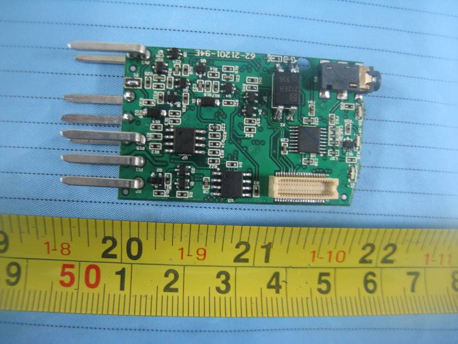
Click to zoom
Application Details
- Equipment Class
- PCB - PCS Licensed Transmitter
- Date of Grant
- Jul 29, 2011
- Application Purpose
- Original Equipment
- Date of Application
- Jul 29, 2011
- Equipment Note
- OBD Smart
- Frequency Range
- 1850.20000000 - 1909.80000000
- Country
- China
Documents & Files
Document Text
Text extracted from the exhibit documents filed with the FCC. Open a document above to read the original.
Users Manual
Shenzhen Sinocastel Electronics Technology Investment Co., Ltd OBD Smart Product Guide One.Product introduction iDD‐212 is based on OBDII/EOBD standard protocols, an intelligent terminal with tracking and remote diagnostic function. It combines the world leading GPS global statistics positioning technology, GPRS global mobile data communications technology, Bluetooth data transfer technology and intelligent control technology all in one. OBD Smart Terminal is divided into two versions iDD‐212G is consisted with OBD diagnostics module and GSM communications modules, and has optional external G‐Mouse (Model: HT‐166U). This terminal will deliver vehicles live data and GPS data to the back‐end server via GPRS. The server platforms will analysis, statistics, storage and display to user. IDD‐212B is consisted with OBD diagnostics module and Bluetooth communication modules, and has optional external G‐Mouse (Model: HT‐166U). This terminal will deliver vehicle live data and GPS data to the vehicle display via Bluetooth communication technique. Car display will analysis, statistics, storage and display to user in real‐time. Two.Product function 1) OBD protocol types supported J1850‐VPW / J1850‐PWM / ISO9141‐2 / KWP2000 / ISO15765‐4(CAN) 2) GPS OBD Smart has GPS satellite signal reception, enabling global positioning. 1. Real‐time monitoring OBD Smart terminal can keep contact with control center through GSM features for enabling real‐time monitoring. 2. View vehicle location User can visit our website: http://www.uuroad.com or use vehicle display monitor to check view‐time position. 3. Abnormal alarm When the following conditions beyond the default value data, OBD Smart terminal will send back an extension alarm to server and accompanied by “Tick‐tick‐tick..” alarm tone including: Engine speed, vehicle speed, battery voltage, temperature, hard acceleration, hard deceleration, parking without ignition off, towed. Note: For details,please see this handbook – Installation guide – Parameter setting 4. Mileage and fuel consumption statistics When the stroke end, OBD Smart Terminal will gather statistics of driving mileage and average fuel mileage by itself and report to the backend servers. 5. Remote installation and maintenance Through http://www.uuroad .com, remote parameter setting and maintenance can be done into OBD Smart terminal. 6. Diagnostic function Upon user’s request, OBD Smart Terminal can read/clear the vehicle fault codes, clear fault warning light, real‐time analysis by back‐end server, display fault information, and also provide maintenance recommendation to prevent high maintenance cost. Three.Installation Guide 1. Account registration (iDD‐212G) For specific steps, please visit http://www.uuroad.com 2. SIM card installation (iDD‐212G) Remove the SIM card slot cover and insert the SIM card into the card slot (Note: SIM card gap and slot miter edge must fit), then replace the device cover (Note: Align the SIM card within the SIM card slot and gently push) 3. Parameter settings Download and install from the site preference tools. Set the iDD‐212G terminal and connected to PC through USB cable. Open the setup software and set up part of parameter based on individual vehicles condition. IDD‐212B terminal can set parameters directly through Bluetooth display. 4. Terminal installation Stop and turn off the vehicle and insert the G‐Mouse into the function interface. Light up and flat on the car. Also ensure that no block of metal and other items. At the end, firmly connected to the OBD diagnostic block. (Individual model may need OBD extension cable) 5. Use After terminal can connect to vehicle OBD diagnostic block, red light lit and will accompanied with “Beep” one‐tone that means successful. In the same time, green light flashes to indicate that the terminal is trying to communication with the vehicles. Start the engine and wait a bit, green light will be lit and accompanied with “Di‐ Di” two‐tone that means connection is successful. For the G version, yellow light starts blinking that means terminal is searching for GSM network. Then yellow light is changing to slow blinking and accompanied with “tick‐tick‐tick” three‐tone that means terminal is connected to GSM network. Engine off, green light is blinking at about 1‐5 minutes with “tick‐tick‐tick” three‐tone that means the terminal disconnected from the network. After then, terminal will go into sleep mode and accompanied with ‘tick” one‐tone that mean terminal can be removed out of the OBD diagnostic block. In additional, light lit when G‐Mouse power on, blinking when positioning. Four.Specifications 1. External interface Multi‐interface (G‐Mouse access port and parameters access port), SIM card insert port, OBD diagnostic connector, Power indicator (P), GSM module indicator (C), OBD Diagnostic light (O), as shown in Picture 1 2. Technical parameters: Working voltage 9~16V DC Normal working current <150 [email protected] Positioning GPS statistics positioning Standby working current <[email protected] Location positioning accuracy ≤15m Save working current <[email protected] Speed positioning accuracy ≤0.1m/s Working temperature -30°C~+70°C Network GPRS/Bluetooth Storage temperature -40°C~+85°C GSM band 850/900/1800/1900MHz Relative humanity 5%~°95% no frost Backup battery 3.1V/5.5mAH (Lithium) Dimension 55*50*28mm(L*W*H) Five.Disclaimer 1. This handbook is only applies to OBD Smart Terminal. 2. This handbook is only applies to the vehicle with OBD II/EOBD 3. In order to work properly, G‐Mouse must be with satellite communication. The device function may be affected in electromagnetic shielding area or bunker place. 4. iDD‐212G terminal have built‐in wireless communication module. It should be used as far as possible away from fuel depots, chemical plants and other areas could cause an explosion. Most sensitive to external RF sites (such as gas stations, hospitals and school, etc.) may be equipped with radio frequency jamming equipment, the interference of s…
Text truncated - open the document above for the full version.
Cover Letter(s)
TCB GRANT OF EQUIPMENT AUTHORIZATION TCB Certification Issued Under the Authority of the Federal Communications Commission By: RFI Global Services Ltd Pavilion A Ashwood Park, Ashwood Way Basingstoke, Hampshire, RG23 8BG United Kingdom Date of Grant: 06/05/2009 Application Dated: 06/04/2009 Telit Communications S.p.A. Viale Stazione di Prosecco 5/b Trieste, 34010 Italy Attention: Brian Tucker , Global VP, Quality NOT TRANSFERABLE EQUIPMENT AUTHORIZATION is hereby issued to the named GRANTEE, and is VALID ONLY for the equipment identified hereon for use under the Commission's Rules and Regulations listed below. FCC IDENTIFIER: RI7GE865 Name of Grantee: Telit Communications S.p.A. Equipment Class: PCS Licensed Transmitter Notes:Quadband GSM/ GPRS Module Modular Type:Single Modula r Grant Notes FCC Rule Parts Frequency Range (MHZ) Output Watts Frequency Tolerance Emission Designator 22H824.2 - 848.8 1.51 1.0 PM 300KGXW 24E1850.2 - 1909.8 0.87 1.0 PM 300KGXW Single modular approval. Power Output listed is conducted. This device contains functions that are not operational in U.S. Territories. This filing is only applicable for US operations. The antenna gain, including cable loss, must not exceed 3.0dBi at 1900 MHz / 1.4dBi at 850 MHz as defined in 2.1091 and 1.1307 of the rules for satisfying RF exposure compliance. The antenna(s) used for this transmitter must be installed to provide a separation distance of at least 20 cm from all persons and must not be collocated or operating in conjunction with any other antenna or transmitter. The final product operating with this transmitter must include operating instructions and applicable warnings, as described in this filing for end users and installers to satisfy RF exposure compliance requirements. OEM integrators must be informed of the specific requirements.
ID Label/Location Info
EXHIBIT A - FCC ID LABELING AND LOCATION FCC ID Label FCC ID Label Location Label here The label shown shall be permanently affixed at a conspicuous location on the device and be readily visible to the user at the time purchase (Labeling requirements per 2.925)
Internal Photos
EXHIBIT C - EUT INTERNAL PHOTOGRAPHS EUT – Internal View 1 EUT –Internal View 2 EUT –Internal View 3 EUT –Internal View 4 EUT – 62-21201-94E Board Top View EUT –62-21201-94E Board Bottom View EUT – 62-21202-74D Board Top View EUT – 62-21202-74D Board Shielding off Top View EUT – 62-21202-74D Board Bottom View EUT – 62-21203-64E Board Top View EUT – 62-21203-64E Board Bottom View EUT – 62-21204-64B Board Top View EUT –62-21204-64B Board Bottom View
RF Exposure Info
Bay Area Compliance Laboratories Corp. (Shenzhen) FCC ID: ZRT212 Report No.: RSZ110530005-00-22H&24E Page 8 of 15 FCC Part 22H/24E Test Report FCC §1.1307 (b) (1) & §2.1091 - MAXIMUM PERMISSIBLE EXPOSURE (MPE) Applicable Standard According to FCC §1.1307 (b)(1) and §2.1091, systems operating under the provisions of this section shall be operated in a manner that ensures that the public is not exposed to radio frequency energy level in excess of the Commission’s guidelines. Limits for Maximum Permissible Exposure (MPE) (B) Limits for General Population/Uncontrolled Exposure Frequency Range (MHz) Electric Field Strength (V/m) Magnetic Field Strength (A/m) Power Density (mW/cm 2 ) Averaging Time (minutes) 0.3–1.34 614 1.63 *(100) 30 1.34–30 824/f 2.19/f *(180/f²) 30 30–300 27.5 0.073 0.2 30 300–1500 / / f/1500 30 1500–100,000 / / 1.0 30 f = frequency in MHz; * = Plane-wave equivalent power density; MPE Calculation The MPE calculation as given in FCC OET Bulletin 65, page 19 is used to calculate the safe operating distance for the user. S = PG/4πR² Where: S= power density (in appropriate units, e.g. mW/cm 2 ); P = power input to the antenna (in appropriate units, e.g., mW); G = Antenna Gain (relative to an isotropic radiator) R = distance to the center of radiation of the antenna (appropriate units, e.g., cm); Antenna Gain Conducted Output Power Frequency (MHz) (dBi) (numeric) (dBm) (mW) Evaluation Distance (cm) Power Density (mW/cm 2 ) MPE Limit (mW/cm 2 ) Cellular Band (Part 22H) 848.8 1.0 1.26 31.87 1538.15 20 0.386 0.566 PCS Band (Part 24E) 1909.8 2.0 1.58 30.41 1099.01 20 0.345 1.0 Result: The device meets FCC MPE limit at 20 cm distance, RF exposure information has been addressed in the user manual.
Test Report
Note: This test report is prepared for the customer shown above and for the equipment described herein. It may not be duplicated or used in part without prior written consent from Bay Area Compliance Laboratories Corp. This report must not be used by the customer to claim product certification, approval, or endorsement by NVLAP*, or any agency of the Federal Government. * This report contains data that are not covered by the NVLAP accreditation and are marked with an asterisk “★” (Rev.2) TEST REPORT For Shenzhen Sinocastel Electronics Technology Investment Co., Ltd. 5/F, 5 th Building, Software Park, No.2 Gaoxin C. 3rd Road, Hi-Tech. Industrial Park, Nanshan, Shenzhen, Guangdong, China FCC PART 22H, PART 24E FCC ID: ZRT212 Report Type: Original Report Product Type: OBD Smart Test Engineer: Sula Huang Report Number: RSZ110530005-00-22H&24E Report Date: 2011-07-30 Reviewed By: Merry Zhao EMC Engineer Test Laboratory: Bay Area Compliance Laboratories Corp. (Shenzhen) 6/F, the 3rd Phase of WanLi Industrial Building, ShiHua Road, FuTian Free Trade Zone Shenzhen, Guangdong, China Tel: +86-755-33320018 Fax: +86-755-33320008 www.baclcorp.com.cn Bay Area Compliance Laboratories Corp. (Shenzhen) FCC ID: ZRT212 Report No.: RSZ110530005-00-22H&24E Page 2 of 15 FCC Part 22H/24E Test Report TABLE OF CONTENTS GENERAL INFORMATION.......................................................................................................................................3 PRODUCT DESCRIPTION FOR EQUIPMENT UNDER TEST (EUT) .....................................................................................3 OBJECTIVE...................................................................................................................................................................3 RELATED SUBMITTAL(S)/GRANT(S).............................................................................................................................3 TEST METHODOLOGY..................................................................................................................................................3 TEST FACILITY.............................................................................................................................................................3 SYSTEM TEST CONFIGURATION ..........................................................................................................................5 DESCRIPTION OF TEST CONFIGURATION......................................................................................................................5 EUT EXERCISE SOFTWARE..........................................................................................................................................5 EQUIPMENT MODIFICATIONS.......................................................................................................................................5 LOCAL SUPPORT EQUIPMENT LIST AND DETAILS........................................................................................................5 CONFIGURATION OF TEST SETUP.................................................................................................................................5 BLOCK DIAGRAM OF TEST SETUP................................................................................................................................6 SUMMARY OF TEST RESULTS ...............................................................................................................................7 FCC §1.1307 (B) (1) & §2.1091 - MAXIMUM PERMISSIBLE EXPOSURE (MPE)..................................................8 APPLICABLE STANDARD..............................................................................................................................................8 MPE CALCULATION.....................................................................................................................................................8 FCC §2.1046, §22.913 (A) & §24.232 (C) - RF OUTPUT POWER...........................................................................9 APPLICABLE STANDARD..............................................................................................................................................9 TEST PROCEDURE........................................................................................................................................................9 TEST EQUIPMENT LIST AND DETAILS...........................................................................................................................9 TEST DATA................................................................................................................................................................10 FCC §2.1053, §22.917 & §24.238 - SPURIOUS RADIATED EMISSIONS ...........................................................12 APPLICABLE STANDARD............................................................................................................................................12 TEST PROCEDURE......................................................................................................................................................12 TEST EQUIPMENT LIST AND DETAILS.........................................................................................................................12 TEST DATA................................................................................................................................................................13 PRODUCT SIMILARITY DECLARATION LETTER..........................................................................................15 Bay Area Compliance Laboratories Corp. (Shenzhen) FCC ID: ZRT212 Report No.: RSZ110530005-00-22H&24E Page 3 of 15 FCC Part 22H/24E Test Report GENERAL INFORMATION Product Description for Equipment under Test (EUT) The Shenzhen Sinocastel Electronics Technology Investment Co.,Ltd.’s product, model number: iDD-212G (FCC ID: ZRT212) (the "…
Text truncated - open the document above for the full version.
Test Setup Photos
EXHIBIT D - TEST SETUP PHOTOGRAPHS Below 1 GHz: Radiated Emissions - Front View Below 1 GHz: Radiated Emissions - Rear View Above 1 GHz: Radiated Emissions - Front View Above 1 GHz: Radiated Emissions - Rear View
Contact Information
Applicant
Ling Li(Standardization Engineer)
Test Firm
Bay Area Compliance Laboratory Corp. (Shenzhen)John Chan
Technical Specifications
| # | Rule Parts | Frequency Range | Power Output | Emission | Tolerance |
|---|---|---|---|---|---|
| 2 | 24E | 1.85 GHz - 1.91 GHz | 1.099 W | 300KGXW | 1 ppm |