Text extracted from the exhibit documents filed with the FCC. Open a document above to read the original.
Wireless Flash Drive User manual Introduction Wi-Disk is a portable flash storage device that allows you to stream digital media content wirelessly (such as audios, photos, videos, texts etc.) to your IOS/Android/Windows devices. Serving as its own wireless network, Wi-Disk is equipped with high capacity lithium-polymer battery that gives you up to 4 hours of continuous access to your digital library anywhere you go. Available in 16GB to 64GB capacities and simple to set up, Wi-Disk is the perfect solution for expanding your on-the-go media library with devices that have no way of adding to their storage capacity. Packing List Components Quantity Wi-Disk Device 1 Power Switching Adaptor 1 USB Cable 1 User Manual 1 Product Appearance Symbol Name Description A POWER Slide up to turn on and down to turn off B DC PORT Charging(5V) C USB PORT D Wi-Fi Indicator E Power Indicator F Charging Indicator Steps 1. Switch ON Slide the Power button A up to “ON” position, Wi-Disk will start to work with the yellow indicator shines. Wi-Disk will start to emit Wi-Fi signal 15 seconds after and the blue indicator would shine. Connect the mobiledevices with it and you can start to enjoy the digital contents in it. Switch OFF In the ON condition, slide the Power button A to “OFF” position and Wi-Disk would stop working. Wi-Disk will turn off automatically after battery consumed. Please charge the battery before using again. If Wi-Disk shock unexpectedly, please switch it off and switch on again. 2. Battery Management and Charging Please fully charge the Wi-Disk for the first time using. When the indicator twinkles rapidly and become darker, it indicates that battery would consume soon. Please charge in time. The charging indicator C would light up when the adaptor is connected to Wi-Disk to charge and would light off once battery is fully charged. Note: In order to keep the battery working to its full potentiality, please pay attention to the following advices: 1) Don’t charge the battery in excessively high temperatures. 2) Unnecessary to charge after battery consumed, you can charge the battery even when there is still power left inside without it affecting the lifespan of the battery. 3) In order to maintain the battery in good condition, make sure to charge it for at least one time every two weeks if the device hadn’t been used for a long time.。 3. How to Operate with WIDISK Connect iPad, iPhone, iPod touch or Android MID to the WIFI signal of WIDISK. Open the browser(e.g. Safari in IOS),type in 192.168.2.1,and click enter into the main page of Wi-Disk. Select and tap the digital contents(photos/ videos/ audios/ texts) you like Wi-Disk supports the following format Audio:mp3, wav, wma Video:mp4, mov,m4v Image:bmp, jpeg, jpg, png Texts:pdf, doc, ppt, txt, xls Note: While reading some digital contents, some mobile devices may download the files to open. 4. Setting The Wi-Disk Wi-Fi signal is defaulted to be open and under the name ”Wi-Disk”. User can rename the device and secure it with passwords the first time to use it. 1. In the main page of Wi-Disk, tape Setting“ ” on the right-up corner and the following window will pop-up. Select Enable Security. 2. Rename it as you like and type in the password to secure it. 3. Tap into the following window and reconnect your devices after 1 minute. 4. Add shortcuts to launcher To make it easier to read the contents inside, you can add shortcut to the launcher. And you can simply tap the shortcut after connecting to its Wi-Fi signal. IOS devices for example,tap ,select Add to Home Screen and “WDISK” icon would be created. Android device(4.0 as below) In the main page of WI-Disk, click buttons to the right of address bar, tap ”Add to”, select Home screen,and press OK to finish. 5. Reset: In case the user forget the password, please press and hold the Reset buttons for 3 second s, then release. The device would restart and recover to the factory default mode. Technical Specifications Built-in Flash Flash Memory: 16GB(Optional 32GB/64GB) Built-in Lithium rechargeable battery Power Supply AC charger: DC 5V/1.5A Music Function MP3, WMA, WAV Video Function mp4, mov,m4v Photo Browse JPG, JPEG, BMP, GIF Office Files pdf, doc, ppt, txt, xls Main chip set 802.11b/g/n WI-FI Function Work Frequency 2.4GHz Working temperature -5 - 60 °C Languages English, Chinese Operation systems supported Windows98SE/ME/2K/XP FCC Statement This equipment has been tested and found to comply with the limits for a Class B digital device, pursuant to part 15 of the FCC rules. These limits are designed to provide reasonable protection against harmful interference in a residential installation. This equipment generates, uses and can radiate radio frequency energy and, if not installed and used in accordance with the instructions, may cause harmful interference to radio communications. However, there is no guarantee that interference will not occur in a particular installation. If this equipment does cause harmful interference to radio or television reception, which can be determined by turning the equipment off and on, the user is encouraged to try to correct the interference by one or more of the following measures: -Reorient or relocate the receiving antenna. -Increase the separation between the equipment and receiver. -Connect the equipment into an outlet on a circuit different from that to which the receiver is connected. -Consult the dealer or an experienced radio/TV technician for help. RF warning statement: The device has been evaluated to meet general RF exposure requirement. The device can be used in portable exposure condition without restriction. Caution! The manufacturer is not responsible for any radio or TV interference caused by unauthorized modifications to this equipment. Such modifications could void the user authority to operate the equipment. 2.4GHz, channel 1-11
Flastar Technology Co., LTD.Limited Channel Declaration Number: CF309 Version: V01 Date: 08-09-2011 (This form must be used and submitted for applications concerning equipment that may risk operating on non-U.S. frequencies that not allowed to use in the U.S., or equipment that may risk operating beyond the frequency channels for which it is certified.) To: Federal Communications Commission 7345 Oakland Mills Road Columbia MD 21046 Attention: Application Examiner / Review Engineer Subject: Amount of Channels limited for devices marketed in the US Hereby, we: (the applicant company) Company NameFlastar Technology Co., LTD. Address:3F-4F, 43 Building, Baotian Industrial Zone, Xixiang, Bao'an Postal/Zip:City:ShenzhenState/Province:GuangdongCountry:China declare that this device identified by: Grantee Code (CG)Product Code FCC ID:ZS7-WDXX (below, please provide the channels and frequencies supported by this device) only supports IEEE802.11b/g/n(HT20) channel 1-11 (2412–2462 MHz) for marketing and use in the US. The end user will not be able to select any other channel or non US frequency that could violate the restricted bands in the US. (Attestation) (the applicant company or its authorized representative) City and Country:Date:Name: (this must be a person) Function:Signature: (or official company stamp) Enschede, The Netherlands15-06-2012Mark Koop (authorized agent) Manager
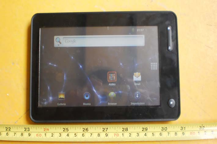
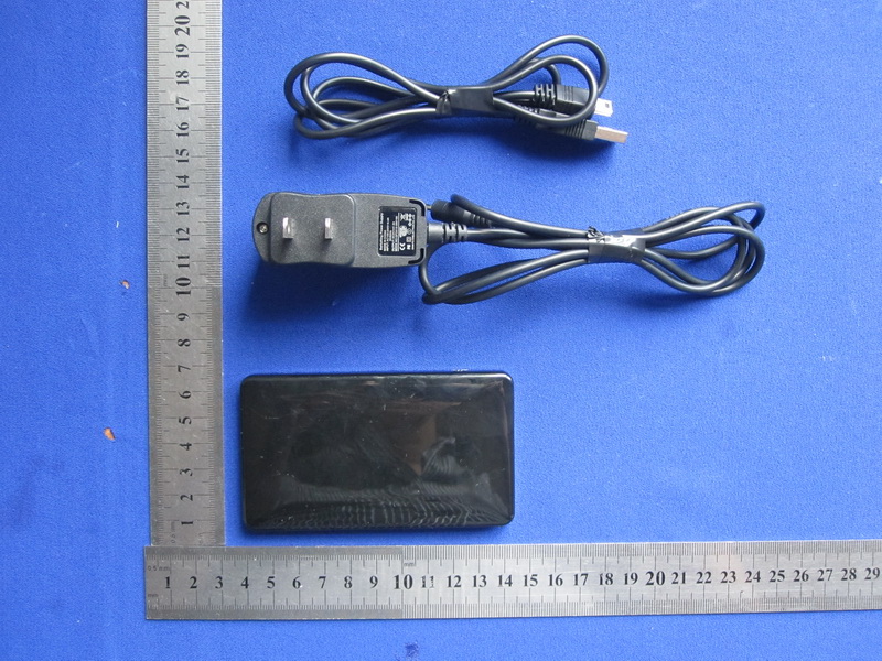
Report No.: TB-RF123977 Page: 3 of 9 TB-RF-075-1.0 Appendix III EUT External Photographs Photo 1 Appearance of EUT Photo 2 Appearance of EUT Report No.: TB-RF123977 Page: 4 of 9 TB-RF-075-1.0 Photo 3 Appearance of EUT Photo 4 Appearance of EUT
Report No.: TB-FCC123977 Page: 1 of 9 TB-RF-074-1.0 Appendix IID Label FCC ID: ZS7-WDXX This device complies with part 15 of the FCC Rules. Operation is subject to the following two conditions: (1) This device may not cause harmful interference, and (2) this device must accept any interference received, including interference that may cause undesired operation. Flastar model: WD01 Note: There are similar labels as shown above for other models, where only the model name is replaced WD02, WD03, WD04, WD05, WD06, WD07, WD08, WD09, WD10by: WD02, WD03, WD04, WD05, WD06, WD07, WD08, WD09, WD10
Report No.: TB-RF123977 Page: 2 of 9 TB-RF-075-1.0 Appendix II ID Label Location FCC ID LOCATION
Report No.: TB-RF123977 Page: 5 of 9 TB-RF-075-1.0 Appendix IV EUT Internal Photographs Photo 5 Internal of EUT Photo 6 Internal of EUT Report No.: TB-RF123977 Page: 6 of 9 TB-RF-075-1.0 Photo 7 Internal of EUT Photo 8 Appearance of PCB Report No.: TB-RF123977 Page: 7 of 9 TB-RF-075-1.0 Photo 9 Appearance of PCB Photo 10 Appearance of PCB Antenna
Shenzhen Toby Technology Co., Ltd. Report No.: TB-FCC123977 Page: 1 of 2 TB-RF-075-1.0 10/F., A Block, Jiada R & D Bldg., No.5 Songpingshan Road, Science & Technology Park, Nanshan District, Shenzhen, China Tel: +86 75526509301 Fax: +86 75526509195 RF Exposure Evaluation FCC ID: ZS7-WDXX 1. Client Information Applicant : Flastar Technology Co., Ltd. Address : 3F-4F, 43 Building, Baotian Industrial Zone, Xixiang, Bao'an, Shenzhen, China Manufacturer : Flastar Technology Co., Ltd. Address : 3F-4F, 43 Building, Baotian Industrial Zone, Xixiang, Bao'an, Shenzhen, China 2. General Description of EUT EUT Name : Wireless Flash Drive Models No. : WD01, WD02, WD03, WD04, WD05, WD06, WD07, WD08, WD09, WD10 Model Difference : The different models are identical in schematic, structure and critical component, the only different is the appearance. Operation Frequency: 2412MHz~2462MHz Number of Channel: 11 Channels see note (2) Out Power 802.11b: 12.90 dBm 802.11g: 11.94dBm 802.11n (20M): 11.69 dBm Antenna Gain: 0 dBi Chip Antenna Modulation Type: 802.11b: CCK, QPSK, BPSK 802.11g: OFDM 802.11n (20M): OFDM Product Description : Bit Rate of Transmitter: 802.11b:11/5.5/2/1 Mbps 802.11g:54/48/36/24/18/12/9/6 Mbps 802.11n:up to 150Mbps Power Supply : DC Voltage supplied from AC/DC adapter DC Voltage supplied from Li-Polymer battery Power Rating : AC Adapter: Input: 100~240V 50/60Hz 0.4A Output: 5V 1.5A DC 3.7V 2000mAh from Li-Polymer battery More information about the equipment, please refer to the User Manual. Report No.: TB-FCC123977 Page: 2 of 2 TB-RF-075-1.0 MPE Calculations 1. No Evaluation required if power is below (60/f(GHz) mW) where f is the transmit frequency of the EUT. 2. Calculation: EIRP= P+G Where P=Conducted Output Power (dBm) G=Power Gain of the Antenna (dBi) So Test Mode Conducted Power (dBm) Antenna Gain (dBi) EIRP (dBm) EIRP (mW) 802.11b 12.90 0 12.90 19.498 802.11g 11.94 0 11.94 15.632 802.11n(20M) 11.69 0 11.69 14.757 3. Conclusion: No SAR Evaluation required since Transmitter EIRP is bellow FCC threshold. Note For a more detailed features description, please refer to the RF Test Report.
Shenzhen Toby Technology Co., Ltd. Report No.: TB-FCC123977 Page: 1 of 62 TB-RF-074-1.0 10/F., A Block, Jiada R & D Bldg., No.5 Songpingshan Road, Science & Technology Park, Nanshan District, Shenzhen, China Tel: +86 75526509301 Fax: +86 75526509195 FCC Radio Test Report FCC ID: ZS7-WDXX Report No. : TB-FCC123977 Applicant : Flastar Technology Co., Ltd. Equipment Under Test (EUT) EUT Name : Wireless Flash Drive Model No. : WD01 Serial No. : WD02, WD03, WD04, WD05, WD06, WD07, WD08, WD09, WD10 Brand Name : N/A Receipt Date : 2012-05-29 Test Date : 2012-05-30 to 2012-06-11 Issue Date : 2012-06-12 Standards : FCC Part 15, Subpart C(15.247) Test Method : ANSI C63.4:2003 Conclusions : PASS In the configuration tested, the EUT complied with the standards specified above, The EUT technically complies with the FCC requirements Test/Witness Engineer : Approved& Authorized : This report details the results of the testing carried out on one sample. The results contained in this test report do not relate to other samples of the same product. The manufacturer should ensure that all products in series production are in conformity with the product sample detailed in the report. Report No.: TB-FCC123977 Page: 2 of 62 TB-RF-074-1.0 Contents CONTENTS.............................................................................................................................................2 1. GENERAL INFORMATION ABOUT EUT.............................................................................4 1.1 Client Information.................................................................................................................4 1.2 General Description of EUT (Equipment Under Test)...................................................4 1.3 Block Diagram Showing The Configuration of System Tested.....................................5 1.4 Description of Support Units..............................................................................................6 1.5 Description of Test Mode....................................................................................................6 1.6 Description of Test Software Setting................................................................................6 1.7 Test Facility...........................................................................................................................7 2. TEST SUMMARY.......................................................................................................................8 3. CONDUCTED EMISSION TEST.............................................................................................9 3.1 Test Standard and Limit......................................................................................................9 3.2 Test Setup.............................................................................................................................9 3.3 Test Procedure.....................................................................................................................9 3.4 Test Equipment Used........................................................................................................10 3.5 EUT Operating Mode........................................................................................................10 3.6 Test Data.............................................................................................................................10 4. RADIATED EMISSION TEST................................................................................................13 4.1 Test Standard and Limit....................................................................................................13 4.2 Test Setup...........................................................................................................................14 4.3 Test Procedure...................................................................................................................15 4.4 EUT Operating Condition.................................................................................................15 4.5 Test Equipment..................................................................................................................16 4.6 Test Data.............................................................................................................................16 5. RESTRICTED BANDS REQUIREMENT.............................................................................27 5.1 Test Standard and Limit....................................................................................................27 5.2 Test Setup...........................................................................................................................27 5.3 Test Procedure...................................................................................................................27 5.4 EUT Operating Condition.................................................................................................28 5.5 Test Equipment..................................................................................................................28 5.6 Test Data.............................................................................................................................28 6. BANDWIDTH TEST.................................................................................................................35 6.1 Test Standard and Limit....................................................................................................35 6.2 Test Setup...........................................................................................................................35 6.3 Test Procedure...................................................................................................................35 6.4 EUT Operating Condition.................................................................................................35 6.5 Test Equipment...........................…
Text truncated - open the document above for the full version.
Report No.: TB-RF123977 Page: 8 of 9 TB-RF-075-1.0 Appendix V EUT Test Photographs Photo of Setup for Radiated Emission (Above 1 GHz) Photo of Setup for Radiated Emission (Bellow 1 GHz) Report No.: TB-RF123977 Page: 9 of 9 TB-RF-075-1.0 Photo of Setup for Conducted Emission
Rietven 31 · Enschede, Overyssel · Netherlands
| # | Rule Parts | Frequency Range | Power Output |
|---|---|---|---|
| 1 | 15C | 2.41 GHz - 2.46 GHz | 19.50 mW |

Tablet PC
Equipment Class
DTS - Digital Transmission System