Text extracted from the exhibit documents filed with the FCC. Open a document above to read the original.
BT-III Manual VER:0.0 一、 Specifications charger:DC 5V 500mA Built-in lithium battery:DC3.7V 1000mAh 二、 Appearance 三、Function and operation Bluetooth repeater is a set with bluetooth independent control, signal receiving and forwarding, DMX wireless signal transceiver, built-in lithium battery; The function is powerful, unique design, unlike other wireless controller. It enables simultaneously control a variety of KING POINT products, such as LED par lights, fog machines, bubble machines. There are 3 main features and benefits: 1. Independent control In this mode, the repeater can replace Mobile or AIP, directly control the lamp. Before the operation, pair repeater and lighting in the first. When the pairing is completed, the repeater will display all lighting equipment number; select the number you want to control the lighting equipment. After checking, then can control the selected fixtures. Transmission distance: In open areas, accessible transmission distance 30m. Illustrated as follows: LCD Display Battery charging interfacePower Button XLR Male Switch Button Remark: Under this mode, if the controlled machine is same product and 2 same product can be synchronized. If need to connect same product 3-4 sets, can connect BT-II with product as external receiver for the synchronized run. 2. Signal receiving and forwarding Use APP Mobile software of the KING POINT control system to control lighting equipment, due to the limitation of Bluetooth wireless phone signal transmission distance, unable to meet the requirements of the operating distance. Then use the Bluetooth repeater, can receive and forward the control signal of the phone to control signals, extend the signal transmission distance, complete the phone control the lighting equipment. Operation: 1) The repeater paired with the lighting equipment you like to control, select the ID number of the lighting equipment 2) The Mobile paired with the repeater. 3) Select Mobile APP function slider, operate the selected lighting equipment. Wireless transmission distance: In open areas, accessible transmission distance 40-50 m. 30m KPS-890 KPS-890 Bubble Machine FogMachine Repeater Illustrated as follows: Remark: Under this mode, if the controlled machine is same product and 2 same product can be synchronized. If need to connect same product 3-4 sets, can connect BT-II with product as external receiver for the synchronized run. 3. DMX Wireless Control XLR male connect the signal wire of the DMX control, the DMX signal switch to wireless signal and then transmit. The lighting equipment receive the signal of the repeater, and then convert to DMX signal for control the lighting equipment. Operation: 1) The repeater paired with the lighting equipment you like to control, select the ID number of the lighting equipment 30m KPS-890 KPS-891 Fog Machine 10m Bubble Machine RepeaterMobile 2) Connect the signal wire of the DMX control with XLR male of the repeater 3) Operate DMX control, select the function putt of the lighting equipment you like to control, then control lighting equipment. Wireless transmission distance: In open areas, accessible transmission distance 30m. Illustrated as follows 4. Function of the built-in Lithium battery Built-in lithium battery which supply the power to the repeater control board when operating , no external power adapter when the battery runs out, use adapter to charge recycling. The charging time of Lithium battery:5 hours The discharge time of Lithium battery:About 8 hours Bubble Machine Smoke Machine KPS-891 KPS-890 Repeater DMX Control 30m FCC ID:ZUOBT-III 1. This device complies with Part 15 of the FCC Rules. Operation is subject to the following two conditions: (1) This device may not cause harmful interference. (2) This device must accept any interference received, including interference that may cause undesired operation. 2. Changes or modifications not expressly approved by the party responsible for compliance could void the user's authority to operate the equipment. NOTE: This equipment has been tested and found to comply with the limits for a Class B digital device, pursuant to Part 15 of the FCC Rules. These limits are designed to provide reasonable protection against harmful interference in a residential installation. This equipment generates uses and can radiate radio frequency energy and, if not installed and used in accordance with the instructions, may cause harmful interference to radio communications. However, there is no guarantee that interference will not occur in a particular installation. If this equipment does cause harmful interference to radio or television reception, which can be determined by turning the equipment off and on, the user is encouraged to try to correct the interference by one or more of the following measures: Reorient or relocate the receiving antenna. Increase the separation between the equipment and receiver. Connect the equipment into an outlet on a circuit different from that to which the receiver is connected. Consult the dealer or an experienced radio/TV technician for help. FCC Radiation Exposure Statement This equipment complies with FCC radiation exposure limits set forth for an uncontrolled environment. This equipment should be installed and operated with minimum distance 20cm between the radiator & your body
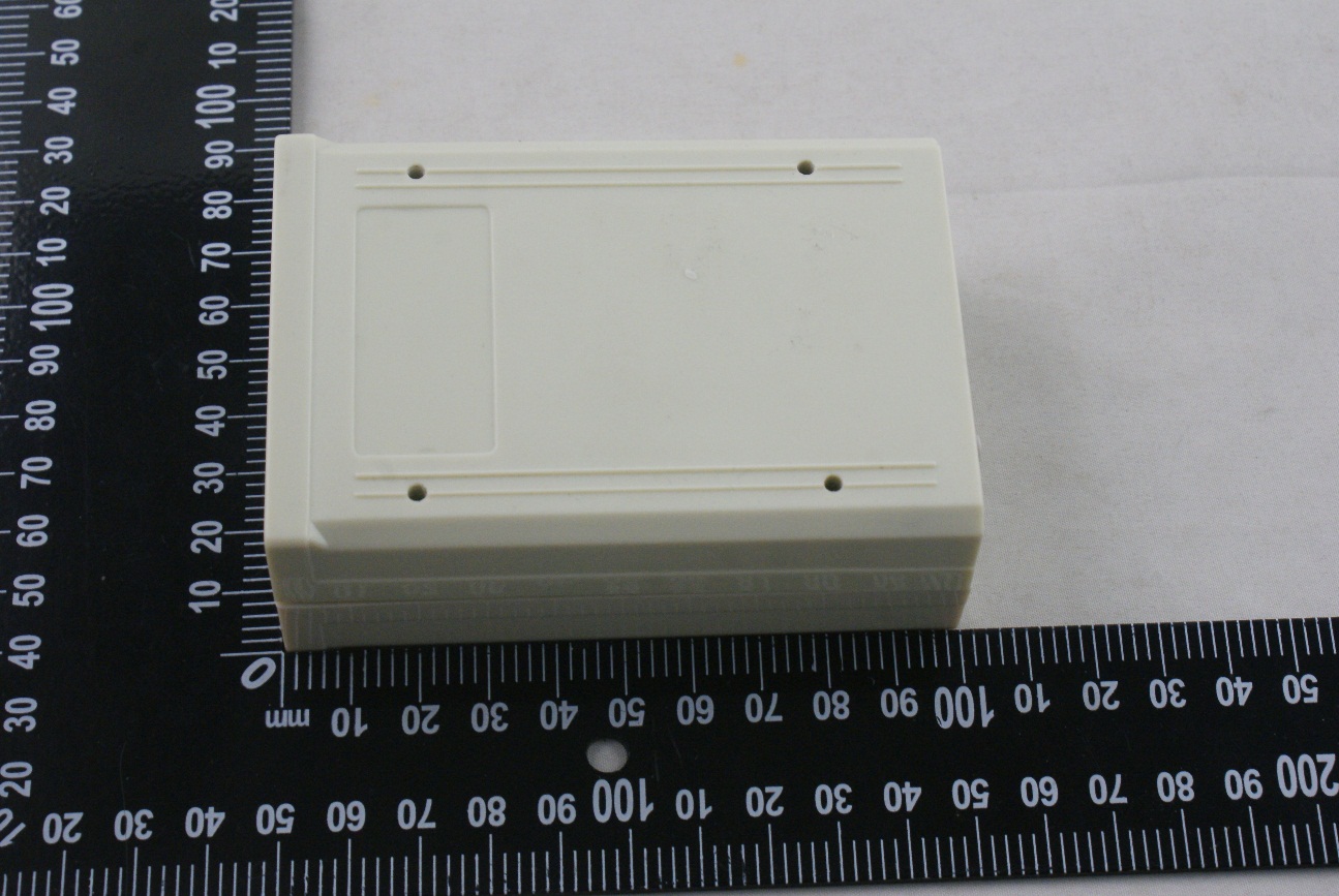
ANNEX C EUT PHOTOS C.1 Appearance of the EUT THE FRONT OF EUT THE BACK OF EUT 2 / 3 THE LEFT OF EUT THE RIGHT OF EUT 3 / 3 THE UP OF EUT THE DOWN OF EUT --END OF REPORT--
ANNEX C EUT PHOTOS C.2 Inside of the EUT EUT UNCOVER VIEW 1 EUT UNCOVER VIEW 2 2 / 8 MAIN BOARD TOP VIEW 1 MAIN BOARD BACK VIEW 1 3 / 8 MAIN BOARD VIEW 2 MAIN BOARD TOP VIEW 3 4 / 8 MAIN BOARD BACK VIEW 3 MAIN BOARD TOP VIEW 4 Module 1 Antenna 2 Antenna 1 Module 2 5 / 8 MAIN BOARD BACK VIEW 4 MAIN BOARD VIEW 5 6 / 8 MODULE 2 TOP VIEW 6 MODULE 2 BACK VIEW 6 7 / 8 MODULE 1 TOP VIEW 7 MODULE 1 BACK VIEW 7 8 / 8 THE PHOTO OF BATTERY --END OF REPORT--
RF Exposure Evaluation For FCC ID: ZUOBT‐III Refer user manual this device is a BT series was designed used in Mobile devices that the minimum distance between human’s body is 20cm. Based on the 47CFR 2.1091, this device belongs to Mobile device. The definition of the category as following: Mobile Derives: CFR Title 47 §2.1091(b) (b) For purposes of this section, a mobile device is defined as a transmitting device designed to be used in other than fixed locations and to generally be used in such a way that a separation distance of at least 20 centimeters is normally maintained between the transmitter’s radiating structure(s) and the body of the user or nearby persons. FCC KDB 447498 D01 General RF Exposure Guidance v05r02 Limit Devices operating in standalone mobile exposure conditions may contain a single transmitter or multiple transmitters that do not transmit simultaneously. A minimum test separation distance ≥ 20 cm is required between the antenna and radiating structures of the device and nearby persons to apply mobile device exposure limits. The distance must be fully supported by the operating and installation configurations of the transmitter and its antenna(s), according to the source‐based time‐averaged maximum power requirements of § 2.1091(d)(2). In cases where cable losses or other attenuations are applied to determine compliance, the most conservative operating configurations and exposure conditions must be evaluated. The minimum test separation distance required for a device to comply with mobile exposure conditions must be clearly identified in the installation and operating instructions, for all installation and exposure conditions, to enable users and installers to comply with RF exposure requirements. For mobile devices that have the potential to operate in portable device exposure conditions, similar to the configurations described in § 2.1091(d)(4), a KDB inquiry is required to determine the SAR test requirements for demonstrating compliance. When the categorical exclusion provision of § 2.1091(c) applies, the minimum test separation distance may be estimated, when applicable, by simple calculations according to plane‐wave equivalent conditions, to ensure the transmitter and its antenna(s) can operate in manners that meet or exceed the estimated distance. The source ‐based time‐averaged maximum radiated power, according to the maximum antenna gain, must be applied to calculate the field strength and power density required to establish the minimum test separation distance. When the estimated test separation distance becomes overly conservative and does not support compliance, MPE measurement or computational modeling may be used to determine the required minimum separation distance. RF Exposure Evaluation Result: FCC (Worst case) According to FCC Part 1.1307, systems operating under the provisions of this section shall be operated in a manner the ensures that the public is not exposed to radio frequency energy level in excess of the commission’s guidelines. Limits for General Population/ Uncontrolled Exposure Frequency Range (MHz) Electric Field Strength(E)(V/m) Magnetic Field Strength (H)(A/m) Power Density (S)(mW/cm2) 0.3‐1.34 614 1.63 (100)* 1.34‐30 824/f 2.19/f (180/f2)* 30‐300 27.5 0.073 0.2 300‐1500 f/1500 1500‐100,000 1.0 MPE calculation formula ൌࡿ ࡳࡼ ࡾ࣊ Where: S = power density P = output power (W) G = power gain of the antenna in the direction of interest relative to an isotropic radiator R = Separation distance between radiator and human body (m) Test result Maximum peak output power at antenna input terminal Ant1(dBm): 3.30 Antenna Gain (typical) Ant1 (dBi): 2.21 Maximum peak output power at antenna input terminal Ant2(dBm): 3.42 Antenna Gain (typical) Ant2 (dBi): 2.21 Total peak output power (Ant1+Ant2) (dBm): 11.14 Total peak output power (Ant1+Ant2) (mW): 13.00 Prediction distance(cm): 20 Predication frequency(MHz): 2402 Power density at predication frequency at 20 cm(mW/cm2): 0.0026 MPE limit for RF exposure at prediction frequency(mW/cm2): 1 FCC Verdict: PASS Note: 1. More power list please refer to RF test report.
Report No.: BL-SZ1550028-601 2 Revision History Version Issue Date Revisions Rev. 01 Ma y. 18, 2015 Initial Issue TABLE OF CONTENTS 1 ADMINISTRATIVE DATA (GENERAL INFORMATION) ........................................................................ 5 1.1 Identification of the Testing Laboratory ............................................................................................ 5 1.2 Identification of the Responsible Testing Location ........................................................................... 5 1.3 Announce ........................................................................................................................................ 5 2 PRODUCT INFORMATION ................................................................................................................... 6 2.1 Applicant ......................................................................................................................................... 6 2.2 Manufacturer ................................................................................................................................... 6 2.3 General Description for Equipment under Test (EUT) ..................................................................... 6 2.4 Technical Information ...................................................................................................................... 7 2.5 Ancillary Equipment ......................................................................................................................... 7 3 SUMMARY OF TEST RESULTS ........................................................................................................... 8 3.1 Test Standards ................................................................................................................................ 8 3.2 Verdict ............................................................................................................................................. 8 4 GENERAL TEST CONFIGURATIONS .................................................................................................. 9 4.1 Test Environments .......................................................................................................................... 9 4.2 Test Equipment List ......................................................................................................................... 9 4.3 Test Configurations ....................................................................................................................... 10 4.4 Description of Test Setup .............................................................................................................. 10 4.4.1 For Antenna Port Test ............................................................................................................ 10 4.4.2 For AC Power Supply Port Test .............................................................................................. 10 4.4.3 For Radiated Test (Below 30 MHz) ......................................................................................... 11 4.4.4 For Radiated Test (30 MHz-1 GHz) ........................................................................................ 11 4.4.5 For Radiated Test (Above 1 GHz) .......................................................................................... 12 4.5 Test Conditions ............................................................................................................................. 12 5 TEST ITEMS ....................................................................................................................................... 13 5.1 Antenna Requirements .................................................................................................................. 13 Report No.: BL-SZ1550028-601 3 5.1.1 Standard Applicable ............................................................................................................... 13 5.1.2 Antenna Anti-Replacement Construction ................................................................................ 13 5.1.3 Antenna Gain ......................................................................................................................... 13 5.2 Output Power ................................................................................................................................ 14 5.2.1 Test Limit ................................................................................................................................ 14 5.2.2 Test Procedure ....................................................................................................................... 14 5.3 6 dB Bandwidth ............................................................................................................................. 15 5.3.1 Limit........................................................................................................................................ 15 5.3.2 Test Procedure ....................................................................................................................... 15 5.4 Conducted Spurious Emission ...................................................................................................... 16 5.4.1 Limit........................................................................................................................................ 16 5.4.2 Test Procedure ....................................................................................................................... 16 5.5 Conducted Emission ..................................................................................................................... 18 5.5.1 Limit........................................................................................................................................ 18 5.5.2 Test Procedure ...........................................................................................................…
Text truncated - open the document above for the full version.
ANNEX B TEST SETUP PHOTOS B.1 Conducted Test Photo B.2 Conducted Emissions Test Photo B.3 Radiated Test Photo Below 30 MHz 30 MHz to 1 GHz Above 1 GHz
| # | Rule Parts | Frequency Range | Power Output |
|---|---|---|---|
| 1 | 15C | 2.40 GHz - 2.48 GHz | 4.34 mW |
WDBOX
Equipment Class
DXX - Part 15 Low Power Communication Device Transmitter