ZUQ849144415800 MHz iDEN RRH
KMW U.S.A., INC.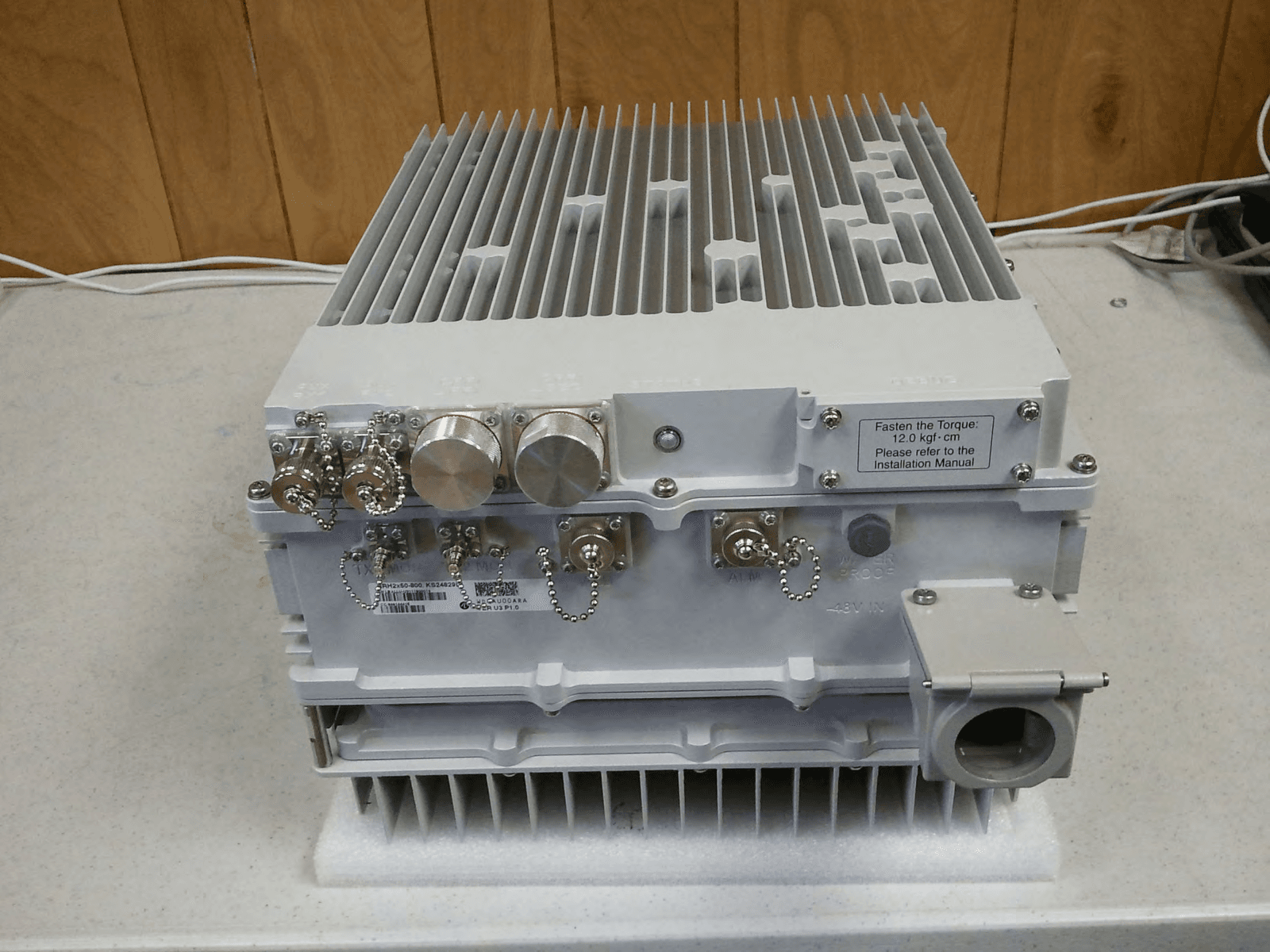
Click to zoom
Application Details
- Equipment Class
- TNB - Licensed Non-Broadcast Station Transmitter
- Date of Grant
- Sep 14, 2011
- Application Purpose
- Original Equipment
- Date of Application
- Sep 14, 2011
- Equipment Note
- 800 MHz iDEN RRH
- Frequency Range
- 862.90000000 - 868.37500000
- Company
- KMW U.S.A., INC.
- Country
- United States
Documents & Files
Document Text
Text extracted from the exhibit documents filed with the FCC. Open a document above to read the original.
Users Manual
iDEN 800MHz RRH iDEN 800MHz RRHiDEN 800MHz RRH iDEN 800MHz RRH U UU User Guide ser Guideser Guide ser Guide 1 iDEN 800MHz RRH User Guide Written by Reviewed by Approved by Joonyong Jang Michael Yoon Michael Yoon iDEN 800MHz RRH iDEN 800MHz RRHiDEN 800MHz RRH iDEN 800MHz RRH U UU User Guide ser Guideser Guide ser Guide 2 Index Contents 1. FCC Information ------------------------------------------------- 3 2. Test Environment ------------------------------------------------ 3 2.1. Preperation List ------------------------------------------ 3 2.2. Testing Environement Configuration --------------- 3 2.3. RRH Setup Procedure --------------------------------- 4 3. Network Configuration ----------------------------------------- 5 4. Operate GUI Program ----------------------------------------- 6 iDEN 800MHz RRH iDEN 800MHz RRHiDEN 800MHz RRH iDEN 800MHz RRH 1. FCC Information RF Exposure compliance must be addressed at the time of licensing 2. Test Environment 2.1. Preperation List • iDEN 800Mhz RRH (Remote Radio Head 800MHz) • PSU (Power Supply Unit) • BBU (Base Band Unit, Alacaltel Lucent) • Optic transceiver 2EA ( Yellow • Optic Cable • RJ45 Ehternet Cable • Laptop computer for RRH GUI 2.2. Testing Environement Configuration iDEN 800MHz RRH iDEN 800MHz RRHiDEN 800MHz RRH iDEN 800MHz RRH U UU User Guide ser Guideser Guide ser Guide 3 RF Exposure compliance must be addressed at the time of licensing . (Remote Radio Head 800MHz) (Power Supply Unit) (Base Band Unit, Alacaltel Lucent) Yellow - 1550nm, Blue- 1310nm) Laptop computer for RRH GUI Testing Environement Configuration iDEN 800MHz RRH iDEN 800MHz RRHiDEN 800MHz RRH iDEN 800MHz RRH U UU User Guide ser Guideser Guide ser Guide 4 • PSU Setting Table Voltage Current Limit Low : -38V 12 A Normal : -48V 9.5 A High : -57V 8 A 2.3. RRH Setup Procedure • •• • Checke PSU Power 48V off • •• • Connect PSU power to RRH Power connector • •• • Connect BBU and RRH with Optic transceiver and Optic cable RRH side; Blue Transceiver (1310nm) BBU side; Yellow Transceiver (1550nm) • •• • Turn on PSU to power up RRH • •• • Make sure computer to join RRH and BBU network. If the computer joined the same network which BBU joined, it is able to access RRH network from the GUI. iDEN 800MHz RRH iDEN 800MHz RRHiDEN 800MHz RRH iDEN 800MHz RRH U UU User Guide ser Guideser Guide ser Guide 5 3. Network Configuration • Setup computer network configuration IP: assigned by ALU (ex; 10.10.10.55) Su bnet mask: 2 55.0.0.0 Default gateway: assigned by ALU (ex; 10.10.10.1) DNS: assigned by ALU • T est network configuration Windows Start > Run > CMD [Enter] C:\> ping RRH IP(10.14.0.196) [Enter] iDEN 800MHz RRH iDEN 800MHz RRHiDEN 800MHz RRH iDEN 800MHz RRH 4. Operate GUI Program • •• • Run RRH GUI Program. Input RRH’s IP and click the Connect button • •• • Setup the carrier configuration on the index to turn o If you want to make CDMA single carrier configuration, please follow below setting and click (A) SET button. Ex) 1FA setup with CDMA signam on Index 3 (Tx; 865.4MHz, Rx; 820.4MHz) Index : 3 STATE : [v] Enable TXCONTAINER : [v] 2 TX2CONTAINER : [v] 2 RX1CONTAINER : [v] 3 RX2CONTAINER : [v] 8 TXFREQ : [v] 865400 RXFREQ : [v] 820400 CARRTYPE : [v] 3G1X iDEN 800MHz RRH iDEN 800MHz RRHiDEN 800MHz RRH iDEN 800MHz RRH U UU User Guide ser Guideser Guide ser Guide 6 Input RRH’s IP and click the Connect button Setup the carrier configuration on the index to turn o n carrier power. If you want to make CDMA single carrier configuration, please follow below setting and click (A) SET button. Ex) 1FA setup with CDMA signam on Index 3 (Tx; 865.4MHz, Rx; 820.4MHz) If you want to make CDMA single carrier configuration, please follow below setting and click (A) SET button.
Users Manual
iDEN 800MHz RRH iDEN 800MHz RRHiDEN 800MHz RRH iDEN 800MHz RRH • •• • Change TXENABLE[v] from DISABLE to ENABLE and click (B)SET button to turn on RF Power iDEN 800MHz RRH iDEN 800MHz RRHiDEN 800MHz RRH iDEN 800MHz RRH U UU User Guide ser Guideser Guide ser Guide 7 TXENABLE[v] from DISABLE to ENABLE and click (B)SET button to turn on RF Power TXENABLE[v] from DISABLE to ENABLE and click (B)SET button to turn on RF Power iDEN 800MHz RRH iDEN 800MHz RRHiDEN 800MHz RRH iDEN 800MHz RRH • •• • If you set up Signal Analyzer , you can monitor carrier p iDEN 800MHz RRH iDEN 800MHz RRHiDEN 800MHz RRH iDEN 800MHz RRH U UU User Guide ser Guideser Guide ser Guide 8 , you can monitor carrier p ower just like below image.
Attestation Statements
1521 E. Orangethorpe Ave. Suite A Fullerton CA 92831 Tel. (714) 515-1 100 Fax.(714) 515-1 134 www.kmwcomm.com CO,\it'¡'UNl(:Al iONS Date: September 3, 2013 Federal Communications Commission Authorization and Evaluation Division 7435 Oakland Mills Road Columbia, Maryland 21046 Application Examiner: An original grant for FCC lD: 2UQ849144415 was issued September 15,2011 . The device is a remote radio head per the definition in C.10 of KDB 935210 D01. We have since realized that the grant needs to be to be updated to reflect a slightly increased output power. The requested changes to the grant are summarized as follows: A revised test report has been issued supporting the requested changes. When comparing the original data with the new data: o There have been no hardware or software modifications. o The output power was measured at the same point on the system o The output power measurements were not bandwidth limited o An RMS detector was used for both original and new data. o The equipment under test used the same software and firmware. The likely difference in test data is that an inaccurate amplitude offset was originally used in the spectrum analyzer. Per the new procedure for allowing grant corrections after 30 days (Dec 2011 FCC-TCB conference call notes), we respectively request that the grant be updated with the requested changes. As the grantee, KMW U.S.A., lNC, accepts responsibility for having reviewed the revised test report. Original grant issued 911512011 FCC Rule PartsFrequency Ranqe (MHZ) Output WattsFrequency Tolerance Emission Desionator 90.691862.9 - 868.37533.420.27 PM 1M27FgW This requestgl312013 FCC Rule PartsFrequency Ranqe (MHZ) Output WattsFrequency Tolerance Emission Desiqnator 90.691862.9 - 868.375600.27 PM1M27F9W Thank you for your consideration of this matter. Best regards, Research & Development ^î:"î'ä"n ,"'ffi'//"
Attestation Statements
NORTHWEST EMC, INC. 22975 NW Evergreen Pkwy, Suite 400 Hillsboro, Oregon 97124 503 844-4066 Fax 503 844-3826 Date: September 3, 2013 Federal communications Commission Authorization and Evaluation Division 7435 Oakland Mills Road Columbia, Maryland 21046 Application Examiner: Northwest EMC Test report # KMWC0027 was used to support an original grant of certification for FCC ID: ZUQ849144415 issued September 15, 2011. After the grant was issued, KMW U.S.A., INC. determined that the grant should have a slightly increased level of output power. Subsequent testing and investigation led us to conclude that likely the test data used in the original report # KMC0027 had inaccurate amplitude offset in the spectrum analyzer. We have issued a revised test report to # KMWC0027 that contains data with accurate amplitude offset in the spectrum analyzer. Best regards, Victor Ratinoff Operations Manager - Irvine, CA Northwest EMC, Inc. Email: [email protected] ph: (949) 861-8918
Cover Letter(s)
Northwest EMC TCB Compliance Opinion Rev. 7/1/10 KMWC0028 Information about the Applicant Grantee (Company Name) KMW U.S.A, Inc. FCC Contact Person Joonyong Jang Address 1521 E Orangethorpe Ave., Suite #A City, State, Zip Fullerton, CA 92831 Job Number KMWC0028 Model 800MHz iDEN RHH FCC ID ZUQ849144415 Agent Approval Type Original Equipment Class TNB Licensed Non-Broadcast Base Station Transmitter Rule Part 90.691 Overview The model 800MHz iDEN RHH, manufactured by KMW U.S.A, Inc. receives and transmits radio signals. The device is a licensed radio device which transmits in the 860 MHz band from 862.275 to 869.000 MHz. Confidentiality requested for allowed files. Request is properly addressed and referenced. Recommendation All items have been resolved and completed to my satisfaction; therefore I recommend this application for approval. Signature Dave Tolman, TCB Committee 9/14/2011
ID Label/Location Info
COMCODE: 849158241 ISSUE#: 1 WORK#: 4 MAR-TEK INDUSTRIES: ISO 9001:2008 REGISTERED Power DC Input: -48V 10A Type 4 Enclosure 849158241 253513 KS-24829, LIST 1For Operating Temperature Ratings Reference The Site Preparation Document Manufactured in Korea for Alcatel-Lucent This device complies with part 15 of the FCC Rules. Operation is subject to the following two conditions: (1) This device may not cause harmful interference, and (2) this device must accept any interference received, including interference that may cause undesired operation. RRH2X50-800 FCC ID: ZUQ849144415 Power DC Input: -48V 10A Type 4 Enclosure 849158241 253513 KS-24829, LIST 1For Operating Temperature Ratings Reference The Site Preparation Document Manufactured in Korea for Alcatel-Lucent This device complies with part 15 of the FCC Rules. Operation is subject to the following two conditions: (1) This device may not cause harmful interference, and (2) this device must accept any interference received, including interference that may cause undesired operation. RRH2X50-800 FCC ID: ZUQ849144415 0.00 35.00 0.00 150.00 12pt Frutiger Roman, 8 & 7pt Helvetica Med Cond, 8 & 6pt Helvetica Medium & 7pt Helvetica Bold ORIGINAL ARTWORK USE FOR REPRODUCTION COMPOSITE SPEC DRAWING FOR REFERENCE ONLY (DO NOT USE FOR REPRODUCTION) Title: 849158241 BOILERPLATE LABEL Designer: PE Drawn: SRJ Checked: Date: 09-02-2011 Date: 09-02-2011 Date: Approved: Date: Client: Alcatel-Lucent - Paul Englert Material Specifications: Font Info: Comcode No.: 849158241 Artmaster Issue#: 1w4 10 mil velvet/matte polycarbonate 8B35V (VTM-2) or equivalent with 3M 467 permanent adhesive Subsurface print Black and Cool Gray 1 OS20000 Drawing Issue#: Mar-Tek Industries • 3545-G South Platte River Drive • Englewood, CO 80110 • tele: 973-293-0165 • fax: 973-293-0164 • email: [email protected] AM ISSUE DESCRIPTIONDATEDRAWN 1w1Initial Release.06-15-2011S. JENSEN 1w2Added CSA symbol, updated enclosure rating & power info06-21-2011S. JENSEN 1w3Added CSA registration number07-13-2011S. JENSEN 1w4Added FCC number and updated FCC statement09-02-2011S. JENSEN Certifications: ALL INFORMATION CONTAINED IN THIS DOCUMENT IS THE PROPERTY OF ALCATEL-LUCENT All units are in millimeters • Tolerance is: 2 places .25mm • Symbology agrees with: ISO 1101 and ISO 1302 Labels are RoHS compliant and conform to Alcatel-Lucent banned substance and environmental hazardous substance requirements in QPS 20.248 & IAA 00266 0035 ASZZA. Artmaster Must Be Obtained By: Label shall meet UL and CSA requirements where applicable. Vendor must be UL and/or CSA approved. Documentation verifying the vendor’s certifications for the material shall be provided by the vendor with each package/container. Die Strike: .02” R 1.50 TYP 1 | Presentation Title | Month 2006 All Rights Reserved © Alcatel-Lucent 2006, #####
Parts List/Tune Up Info
800MHz iDEN RRH - TX Output Power Calibration Procedure 1 TX Output Power Calibarion Procedure - 800MHz iDEN RRH - Rev Who Date Contents V1.0 Andy Ku 09/13/2011 Created 800MHz iDEN RRH - TX Output Power Calibration Procedure 2 • TX Output Power Setting (Tx Gain setting) - Test purpose : To set up TX output power. - Equipment : Power Supply(Agilent 6674A), Power Meter(Agilent E4419B), Power Sensor(Agilent E9300H), Spectrum Analyzer(Agilent N9020A), COBRA(KMW BBU simulator) - Specification : 50W (+47dBm@CDMA 1FA) - Test configuration. - Connect ANT A port to Power Meter and Spectrum Analyzer to measure the output power. - Connect ANT B port to RF 50 Ohm termination. - Set External Power Supply voltage(DC-48V) and current limit(11A). - Turn on the DC -48V power. - Set BBU simulator optic output power as -15dBfs for CDMA 1FA. - Set iDEN800 RRH 865.4MHz 1 carrier configuration at ANT A path and ANT B path with GUI. - Set Path A digital gain as default value (-2dB) and TX A RF attenuator offset value as default value (2dB). - Enable ANT A Path. - Check ANT A Port Output power value to use Power Meter whether +47dBm or not. - If ANT A output power dosen’t meet the spec(+47dBm), adjust the TX RF attenuator to make it +47dBm. - Disable ANT A Path. - Connect ANT B port to Power Meter and Spectrum Analyzer to measure the output power. - Connect ANT A port to RF 50 Ohm termination. 800MHz iDEN RRH - TX Output Power Calibration Procedure 3 - Set Path B digital gain as default value (-2dB) and TX B RF attenuator offset value as default value (2dB). - Enable ANT B Path. - Check ANT B Port Output power value to use Power Meter whether +47dBm or not. - If ANT B output power dosen’t meet the spec(+47dBm), adjust the TX RF attenuator to make it +47dBm. - Disable ANT B Path
Test Report
KMW Communications 800MHz iDEN RRH Report No. KMWC0027 Report Prepared By www.nwemc.com 1-888-EMI-CERT © 2011 Northwest EMC, Inc 22975 NW Evergreen Parkway Suite 400 Hillsboro, Oregon 97124 Certificate of Test Last Date of Test: September 7, 2011 KMW Communications Model: 800MHz iDEN RRH Emissions Test Description Specification Test Method Pass/Fail Field Strength of Spurious Emissions 1 FCC 90.691:2011 ANSI/TIA/EIA-603-C-2004 Pass Conducted Output Power FCC 90.635:2011 ANSI/TIA/EIA-603-C-2004 Pass Occupied Bandwidth 1 FCC 90.691:2011 ANSI/TIA/EIA-603-C-2004 Pass Spurious Emissions at the Antenna Terminals 1 FCC 90.691:2011 ANSI/TIA/EIA-603-C-2004 Pass Frequency Stability FCC 90.213:2011 ANSI/TIA/EIA-603-C-2004 Pass Emission Mask 1 FCC 90.691:2011 ANSI/TIA/EIA-603-C-2004 Pass Note 1: See Sprint Nextel’s Request for Waiver to Permit the operation of Broadband CDMA Technology in the 817 – 824/862 – 869 MHz band. Modifications made to the product See the Modifications section of this report Test Facility The measurement facility used to collect the data is located at: Northwest EMC, Inc. 41 Tesla Ave. Irvine, CA 92618 Phone: (503) 844-4066 Fax: 844-3826 This site has been fully described in a report filed with and accepted by the FCC (Federal Communications Commission) and Industry Canada (Site filing #2834B-1). Approved By: Tim O'Shea, Operations Manager NVLAP Lab Code: 200676-0 This report must not be used to claim product certification, approval, or endorsement by NVLAP, NIST, or any agency of the federal government of the United States of America. Product compliance is the responsibility of the client, therefore the tests and equipment modes of operation represented in this report were agreed upon by the client, prior to testing. This Report may only be duplicated in its entirety. The results of this test pertain only to the sample(s) tested. The specific description is noted in each of the individual sections of the test report supporting this certificate of test. Northwest EMC Revision History Revision 06/29/09 Barometric Pressure The recorded barometric pressure has been normalized to sea level. Revision Number Description Date Page Number 00 None Accreditations and Authorizations FCC Accredited by NVLAP for performance of FCC radio, digital, and ISM device testing. Our Open Area Test Sites, certification chambers, and conducted measurement facilities have been fully described in reports filed with the FCC and accepted by the FCC in letters maintained in our files. Northwest EMC has been accredited by ANSI to ISO / IEC Guide 65 as a product certifier. We have been designated by the FCC as a Telecommunications Certification Body (TCB). This allows Northwest EMC to certify transmitters to FCC specifications in accordance with 47 CFR 2.960 and 2.962. NVLAP Northwest EMC, Inc. is accredited under the National Voluntary Laboratory Accreditation Program (NVLAP) for satisfactory compliance with the requirements of ISO/IEC 17025 for Testing Laboratories. NVLAP is administered by the National Institute of Standards and Technology (NIST), an agency of the U.S. Commerce Department. The NVLAP accreditation encompasses Electromagnetic Compatibility Testing in accordance with the European Union EMC Directive 2004/108/EC, and ANSI C63.4. Additionally, Northwest EMC is accredited by NVLAP to perform radio testing in accordance with the European Union R&TTE Directive 1999/5/EEC, the requirements of FCC, and the RSS radio standards for Industry Canada. Industry Canada Accredited by NVLAP for performance of Industry Canada RSS and ICES testing. Our Open Area Test Sites and certification chambers comply with RSS-Gen, Issue 2 and have been filed with Industry Canada and accepted. Northwest EMC has been accredited by ANSI to ISO / IEC Guide 65 as a product certifier. We have been designated by NIST and recognized by Industry Canada as a Certification Body (CB) per the APEC Mutual Recognition Arrangement (MRA). This allows Northwest EMC to certify transmitters to Industry Canada technical requirements. (Site Filing Numbers - Hillsboro: 2834D-1, 2834D-2, Sultan: 2834C-1, Irvine: 2834B-1, 2834B-2, Brooklyn Park: 2834E-1) CAB Designated by NIST and validated by the European Commission as a Conformity Assessment Body (CAB) to conduct tests and approve products to the EMC directive and transmitters to the R&TTE directive, as described in the U.S. - EU Mutual Recognition Agreement. Australia/New Zealand The National Association of Testing Authorities (NATA), Australia has been appointed by the ACA as an accreditation body to accredit test laboratories and competent bodies for EMC standards. Accredited test reports or assessments by competent bodies must carry the NATA logo. Test reports made by an overseas laboratory that has been accredited for the relevant standards by an overseas accreditation body that has a Mutual Recognition Agreement (MRA) with NATA are also accepted as technical grounds for product conformity. The report should be endorsed with the respective logo of the accreditation body (NVLAP). Accreditations and Authorizations VCCI Accepted as an Associate Member to the VCCI, Acceptance No. 564. Conducted and radiated measurement facilities have been registered in accordance with Regulations for Voluntary Control Measures, Article 8. (Registration Numbers. - Hillsboro: C-1071, R-1025, G-84, C-2687, T- 1658, and R-2318, Irvine: R-1943, G-85, C-2766, and T-1659, Sultan: R-871, G-83, C-3265, and T-1511, Brooklyn Park: R-3125, G-86, G-141, C-3464, and T-1634). BSMI Northwest EMC has been designated by NIST and validated by C-Taipei (BSMI) as a CAB to conduct tests as described in the APEC Mutual Recognition Agreement (US0017). GOST Northwest EMC, Inc. has been assessed and accredited by the Russian Certification bodies Certinform VNIINMASH, CERTINFO, SAMTES, and Federal CHEC, to perform EMC and Hygienic testing for Information Technology Products. As a result of their laboratory assessment, they will ac…
Text truncated - open the document above for the full version.
Test Report
KMW Communications 800MHz iDEN RRH Report #: KMWC0027 Rev 1 Report Prepared By Northwest EMC Inc. NORTHWEST EMC – (888) 364-2378 – www.nwemc.com California – Minnesota – Oregon – New York – Washington WTD 12.5.23 CERTIFICATE OF TEST Last Date of Test: July 26, 2013 KMW Communications Model: 800MHz iDEN RRH Emissions Test Description Specification Test Method Pass/Fail Field Strength of Spurious Emissions 1 FCC 90.691:2013, FCC 2.1053:2013 ANSI/TIA/EIA-603-C-2004 Pass Conducted Output Power FCC 90.635:2013, FCC 2.1046:2013 ANSI/TIA/EIA-603-C-2004 Pass Occupied Bandwidth 1 FCC 90.691:2013, FCC 2.1049:2013 ANSI/TIA/EIA-603-C-2004 Pass Spurious Conducted Emissions 1 FCC 90.691:2013, FCC 2.1051:2013 ANSI/TIA/EIA-603-C-2004 Pass Frequency Stability FCC 90.213:2013, FCC 2.1055:2013 ANSI/TIA/EIA-603-C-2004 Pass Emission Mask 1 FCC 90.691:2013, FCC 2.1049:2013 ANSI/TIA/EIA-603-C-2004 Pass Note 1: See Sprint Nextel’s Request for Waiver to Permit the operation of Broadband CDMA Technology in the 817 – 824/862 – 869 MHz band. Deviations From Test Standards None Approved By: Victor Ratinoff, Operations Manager NVLAP Lab Code: 200676-0 This report must not be used to claim product certification, approval, or endorsement by NVLAP, NIST, or any agency of the federal government of the United States of America. Product compliance is the responsibility of the client, therefore the tests and equipment modes of operation represented in this report were agreed upon by the client, prior to testing. This Report may only be duplicated in its entirety. The results of this test pertain only to the sample(s) tested. The specific description is noted in each of the individual sections of the test report supporting this certificate of test. REV 2012.08.02 REVISION HISTORY Revision Number Description Date Page Number 01 Additional test data 9/13/13 Various Barometric Pressure The recorded barometric pressure has been normalized to sea level. REV 2012.05.24 ACCREDITATIONS AND AUTHORIZATIONS United States FCC - Designated by the FCC as a Telecommunications Certification Body (TCB). Certification chambers, Open Area Test Sites, and conducted measurement facilities are listed with the FCC. A2LA - Accredited by A2LA to ISO / IEC Guide 65 as a product certifier. This allows Northwest EMC to certify transmitters to FCC and IC specifications. NVLAP - Each laboratory is accredited by NVLAP to ISO 17025 Canada IC - Recognized by Industry Canada as a Certification Body (CB). Certification chambers and Open Area Test Sites are filed with IC. European Union European Commission – Validated by the European Commission as a Conformity Assessment Body (CAB) under the EMC directive and as a Notified Body under the R&TTE Directive. Australia/New Zealand ACMA - Recognized by ACMA as a CAB for the acceptance of test data. Korea KCC / RRA - Recognized by KCC’s RRA as a CAB for the acceptance of test data. Japan VCCI - Associate Member of the VCCI. Conducted and radiated measurement facilities are registered. Taiwan BSMI – Recognized by BSMI as a CAB for the acceptance of test data. NCC - Recognized by NCC as a CAB for the acceptance of test data. Singapore IDA – Recognized by IDA as a CAB for the acceptance of test data. Hong Kong OFTA – Recognized by OFTA as a CAB for the acceptance of test data. Vietnam MIC – Recognized by MIC as a CAB for the acceptance of test data. Russia GOST – Accredited by Certinform VNIINMASH, CERTINFO, SAMTES, and Federal CHEC to perform EMC and Hygienic testing for Information Technology products to GOST standards. SCOPE For details on the Scopes of our Accreditations, please visit: http://www.nwemc.com/accreditations/ REV 2013.06.28 FACILITIES Oregon Labs EV01-12 22975 NW Evergreen Pkwy Hillsboro, OR 97124 (503) 844-4066 California Labs OC01-13 41 Tesla Irvine, CA 92618 (949) 861-8918 New York Labs NY01-04 4939 Jordan Rd. Elbridge, NY 13060 (315) 685-0796 Minnesota Labs MN01-08 9349 W Broadway Ave. Brooklyn Park, MN 55445 (763) 425-2281 Washington Labs NC01-05,SU02,SU07 19201 120 th Ave. NE Bothell, WA 98011 (425) 984-6600 VCCI A-0108 A-0029 A-0109 A-0110 Industry Canada 2834D-1, 2834D-2 2834B-1, 2834B-2, 2834B-3 2834E-1 2834C-1 NVLAP NVLAP Lab Code: 200630-0 NVLAP Lab Code: 200676-0 NVLAP Lab Code: 200761-0 NVLAP Lab Code: 200881-0 NVLAP Lab Code: 200629-0 WTD 12.5.23 PRODUCT DESCRIPTION Client and Equipment Under Test (EUT) Information Company Name: KMW Communications Address: 1521 E Orangethorpe Ave., Suite #A City, State, Zip: Fullerton, CA 92831 Test Requested By: Joshua Jang Model: 800MHz iDEN RRH First Date of Test: July 18, 2011 Last Date of Test: July 26, 2013 Receipt Date of Samples: July 18, 2011 Equipment Design Stage: Production Equipment Condition: No Damage Information Provided by the Party Requesting the Test Functional Description of the EUT (Equipment Under Test): CDMA/EVDO Rev A cellular base station transmitting in the 861 – 868.975 MHz band. This corresponds to 3GPP2 Band Class 10 Blocks C + D (Subclass 2 + 3) Testing Objective: To demonstrate compliance to FCC Part 90 requirements See Sprint Nextel’s Request for Waiver to Permit the operation of Broadband CDMA Technology in the 817 – 824/862 – 869 MHz band WTD 12.5.23 CONFIGURATIONS Configuration KMWC0027- 1 EUT Description Manufacturer Model/Part Number Serial Number 800MHz iDen RRH KMW Communications iDen 800 U311210059 Peripherals in test setup boundary Description Manufacturer Model/Part Number Serial Number DC Power Supply Hewlett Packard 6574A 4S36340150 Remote Equipment Outside of Test Setup Boundary Description Manufacturer Model/Part Number Serial Number MXA Signal Analyzer Agilent N9020A MY49100579 MXA Signal Analyzer Agilent N9020A MY49100570 MXG Vector Signal Generator Agilent N5182 MY49180185 Reliability Analyzer KMW Communications COBRA None Remote Laptop Fujitsu A6030 R7908331 Cables Cable Type Shield Length (m) Ferrite Connection 1 Connection 2 RF Cable Yes 3.0m No 800MHz iDen RRH Load RF Cable #2 Yes 3.0m No 800MHz iDen RRH…
Text truncated - open the document above for the full version.
Test Setup Photos
NORTHWEST EMC IMG_0156.JPG IMG_0157.JPG FREQUENCY STABILITY XMit 2010.07.29 NORTHWEST EMC IMG_0153.JPG IMG_0154.JPG FREQUENCY STABILITY XMit 2010.07.29 NORTHWEST EMC IMG_0155.JPG FREQUENCY STABILITY XMit 2010.07.29 NORTHWEST EMC direct 3.JPG direct 1.JPG SPURIOUS EMISSIONS AT THE ANTENNA TERMINALS XMit 2011.04.20 NORTHWEST EMC direct 2.JPG SPURIOUS EMISSIONS AT THE ANTENNA TERMINALS XMit 2011.04.20 NORTHWEST EMC direct 3.JPG direct 1.JPG CONDUCTED OUTPUT POWER XMit 2011.04.20 NORTHWEST EMC direct 2.JPG CONDUCTED OUTPUT POWER XMit 2011.04.20 NORTHWEST EMC direct 3.JPG direct 1.JPG OCCUPIED BANDWIDTH XMit 2011.04.20 NORTHWEST EMC direct 2.JPG OCCUPIED BANDWIDTH XMit 2011.04.20 NORTHWEST EMC IMG_0500.JPG IMG_0493.JPG FIELD STRENGTH OF SPURIOUS EMISSIONS PSA-ESCI 2011.07.07 NORTHWEST EMC IMG_0494.JPG IMG_0495.JPG FIELD STRENGTH OF SPURIOUS EMISSIONS PSA-ESCI 2011.07.07 NORTHWEST EMC IMG_0496.JPG IMG_0497.JPG FIELD STRENGTH OF SPURIOUS EMISSIONS PSA-ESCI 2011.07.07 NORTHWEST EMC IMG_0498.JPG IMG_0499.JPG FIELD STRENGTH OF SPURIOUS EMISSIONS PSA-ESCI 2011.07.07
Contact Information
Applicant
JINHEE LEE
Test Firm
Northwest EMC, Inc.Greg Kiemel
Technical Specifications
| # | Rule Parts | Frequency Range | Power Output | Emission | Tolerance |
|---|---|---|---|---|---|
| 1 | 90.691 | 862.9 MHz - 868.375 MHz | 60 W | 1M27F9W | 0.2700000000 ppm |