ZVS-E169DTP2
invoxia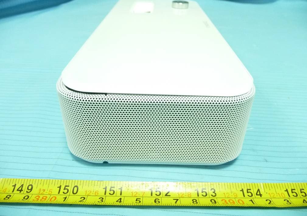
Click to zoom
Application Details
- Equipment Class
- DSS - Part 15 Spread Spectrum Transmitter
- Date of Grant
- Jan 13, 2014
- Application Purpose
- Original Equipment
- Date of Application
- Jan 13, 2014
- Equipment Note
- DTP2
- Frequency Range
- 2402.00000000 - 2480.00000000
- Company
- invoxia
- Country
- France
Documents & Files
Document Text
Text extracted from the exhibit documents filed with the FCC. Open a document above to read the original.
Users Manual
Welcome / Bienvenue E169 U.S. Federal Communications Commission (FCC) Compliance Statement The changes or modifications not expressly approved by the party responsible for compliance could void the user’s authority to operate the equipment. To comply with the FCC RF exposure compliance requirements, this device and its antenna must not be co-located or operating to conjunction with any other antenna or transmitter. This device complies with part 15 of the FCC Rules. Operation is subject to the following two conditions: (1) This device may not cause harmful interference, and (2) this device must accept any interference received, including interfences that may cause undesired operation. Note: This equipment has been tested and found to comply with the limits for a Class B digital device, pursuant to part 15 of the FCC Rules. These limits are designated to provide reasonable protection against harmful interferences in a residential installation. This equipment generates, uses and can radiate radio frequency energy and, if not installed and used in accordance with the intructions, may cause harmful interference to radio communications. However, there is no guarantee that interference will not occur in a particular installation. If this equipment does cause harmful interferences to radio or television reception, which can be determined by turning the equipment off and on, the user is encouraged to try to correct the interference by one or more of the following measures: - Reorient or relocate the receiving antenna. - Increase the separation between the equipment and receiver. - Connect the equipment into an outlet on a circuit different from that to which the receiver is connected. - Consult the dealer or an experienced radio/TV technician for help. FCC Radiation Exposure Statement: This equipment complies with FCC radiation exposure limits set forth for an uncontrolled environment . This transmitter must not be co-located or operating in conjunction with any other antenna or transmitter. This device complies with Industry Canada licence-exempt RSS standard(s). Operation is subject to the following two conditions: (1) this device may not cause interference, and (2) this device must accept any interference, including interference that may cause undesired operation of the device. Le présent appareil est conforme aux CNR d'Industrie Canada applicables aux appareils radio exempts de licence. L'exploitation est autorisée aux deux conditions suivantes : (1) l'appareil ne doit pas produire de brouillage, et (2) l'utilisateur de l'appareil doit accepter tout brouillage radioélectrique subi, même si le brouillage est susceptible d'en compromettre le fonctionnement Under Industry Canada regulations, this radio transmitter may only operate using an antenna of a type and maximum (or lesser) gain approved for the transmitter by Industry Canada. To reduce potential radio interference to other users, the antenna type and its gain should be so chosen that the equivalent isotropically radiated power (e.i.r.p.) is not more than that necessary for successful communication. Conformément à la réglementation d'Industrie Canada, le présent émetteur radio peut fonctionner avec une antenne d'un type et d'un gain maximal (ou inférieur) approuvé pour l'émetteur par Industrie Canada. Dans le but de réduire les risques de brouillage radioélectrique à l'intention des autres utilisateurs, il faut choisir le type d'antenne et son gain de sorte que la puissance isotrope rayonnée équivalente (p.i.r.e.) ne dépasse pas l'intensité nécessaire à l'établissement d'une communication satisfaisante. IC warning: 3 English Box content Lightening, 30 pin and micro-USB cable adapters micro-USB adapters micro-USB cables AC adapter Handset Tablet stand E169 base Lightening, 30 pin and Lightening, 30 pin and Smart holder Ethernet cable Designed and produced by invoxia, Paris 4 En gli sh Adjust volume. Receive and End a call. Bluetooth pairing. Your E169 Phone Voicemail Secret Set up 5 En glish Positioning Pla ce yo ur phone nea r your network soc ket (a nd nea r your mains supply so ck et if you a re us ing a mai ns power a dapter). Connecting the base This phone is powered by PoE (Power over Ethernet), if your network is compatible, or through your mains AC 100-240V supply. 1. Insert the cable suitable to your smartphone into the matching cable adapter. Place it then in the special pocket of the receptacle. 6 En gli sh 3. Slide the cord into place through the interstices under the base. 4. Plug the USB connector to the left USB port at the rear of the device. 7 En glish 5. Insert the suitable adapter to your smartphone, or none if you use a case and your device doesn’t t. To connect a di erent model, please repeat steps 1 to 5. 6. Plug the mains power adapter into the back of the base and into a wall mount socket. English Installing the handset the interstices under the base. 1. Plug the cord of the handset into the right USB port at the back of the base. Slide the cord into place through 7. Plug one end of the Ethernet cable into the LAN connector at the back of the base and into your network telephone socket (PC port is to connect to your computer to provide Internet). 8 En glish 9 2. Place the Smart Holder and the handset on the top of the base. E n glish Guided by a need for simplicity shared with all smartphones and tablets, and for your own e ciency, we have built an App for your convenience. This invoxia app let you configure and use the E169. 1. Dock your smartphone or pair your smartphone or tablet via Bluetotth. 2. Download the invoxia app. 3. Follow the instructions on your device to con gure your invoxia phone based on your network provider’s settings. 4. Once the installation is complete, you’re ready to enjoy the full power of your invoxia phone. You’ll now easily nd your Contacts, Recents, Keypad and Voicemail as well as easily transfer a call, make a conference call, swap between calls, etc. Co nfiguration 10 Dock or conn…
Text truncated - open the document above for the full version.
External Photos
EXHIBIT B - EUT EXTERNAL PHOTOGRAPHS EUT – Full View EUT – Front View (Base) EUT – Rear View (Base) EUT – Top View (Base) EUT – Bottom View (Base) EUT – Left Side View (Base) EUT – Right Side View (Base) EUT – Front View (Handset) EUT – Rear View (Handset) EUT – Top View (Handset) EUT – Bottom View (Handset) EUT – Left Side View (Handset) EUT – Right Side View (Handset) EUT – Adapter View EUT – Adapter Label View
ID Label/Location Info
EXHIBIT A - FCC ID LABELING AND LOCATION FCC ID Label Proposed FCC ID Label Location The label shown shall be permanently affixed at a conspicuous location on the device and be readily visible to the user at the time purchase (Labeling requirements per 2.925) Label here
Internal Photos
EXHIBIT C - EUT INTERNAL PHOTOGRAPHS EUT – Cover off View 1 (Base) EUT – Cover off View 2 (Base) EUT – Main Board 1 Top View (Base) EUT – Main Board 1 Bottom View (Base) EUT – Main Board 2 Top View (Base) EUT – Main Board 2 Bottom View (Base) BT Antenna EUT – Speaker Front View EUT – Speaker Rear View EUT – Cover off View (Handset) EUT – Main Board Top View (Handset) EUT – Main Board Bottom View (Handset) EUT – Main Board Bottom LCD off View (Handset)
Test Report
Note: This test report is prepared for the customer shown above and for the equipment described herein. It may not be duplicated or used in part without prior written consent from Bay Area Compliance Laboratories Corp. FCC PART 15.247 TEST REPORT For invoxia 87 rue du Gouverneur General Eboue, Issy-Les-Moulineaux, France FCC ID: ZVS-E169 Report Type: Original Report Product Type: Desktop phone (Bluetooth device) Test En gineer: Gardon Zhang Re port Number: RSZ131209004-00 Re port Date: 2013-12-25 Reviewed B y: Jimmy Xiao RF En gineer Prepared By: Bay Area Compliance Laboratories Corp. (Shenzhen) 6/F, the 3rd Phase of WanLi Industrial Building ShiHua Road, FuTian Free Trade Zone Shenzhen, Guangdong, China Tel: +86-755-33320018 Fax: +86-755-33320008 www.baclcorp.com.cn Bay Area Compliance Laboratories Corp. (Shenzhen) Report No.: RSZ131209004-00 FCC Part 15.247 Page 2 of 63 TABLE OF CONTENTS GENERAL INFORMATION ....................................................................................................................................... 4 PRODUCT DESCRIPTION FOR EQUIPMENT UNDER TEST (EUT) ..................................................................................... 4 OBJECTIVE ................................................................................................................................................................... 4 RELATED SUBMITTAL(S)/GRANT(S) ............................................................................................................................. 4 TEST METHODOLOGY .................................................................................................................................................. 4 TEST FACILITY ............................................................................................................................................................. 5 SYSTEM TEST CONFIGURATION .......................................................................................................................... 6 DESCRIPTION OF TEST CONFIGURATION ...................................................................................................................... 6 EUT EXERCISE SOFTWARE .......................................................................................................................................... 6 SPECIAL ACCESSORIES ................................................................................................................................................. 6 EQUIPMENT MODIFICATIONS ....................................................................................................................................... 6 SUPPORT EQUIPMENT LIST AND DETAILS .................................................................................................................... 6 EXTERNAL I/O CABLE .................................................................................................................................................. 6 BLOCK DIAGRAM OF TEST SETUP ................................................................................................................................ 7 SUMMARY OF TEST RESULTS ............................................................................................................................... 8 FCC §15.247 (i) & §1.1307 (b) (1) & §2.1091- MAXIMUM PERMISSIBLE EXPOSURE (MPE) .............................. 9 APPLICABLE STANDARD .............................................................................................................................................. 9 RESULT ........................................................................................................................................................................ 9 FCC §15.203 – ANTENNA REQUIREMENT .......................................................................................................... 10 APPLICABLE STANDARD ............................................................................................................................................ 10 ANTENNA CONNECTOR CONSTRUCTION .................................................................................................................... 10 FCC §15.207 (a) – AC LINE CONDUCTED EMISSIONS ..................................................................................... 11 APPLICABLE STANDARD ............................................................................................................................................ 11 MEASUREMENT UNCERTAINTY .................................................................................................................................. 11 EUT SETUP ................................................................................................................................................................ 11 EMI TEST RECEIVER SETUP ....................................................................................................................................... 12 TEST PROCEDURE ...................................................................................................................................................... 12 TEST EQUIPMENT LIST AND DETAILS ......................................................................................................................... 12 CORRECTED FACTOR & MARGIN CALCULATION ....................................................................................................... 12 TEST RESULTS SUMMARY .......................................................................................................................................... 13 TEST DATA ................................................................................................................................................................ 13 FCC §15.205, §15.209 & §15.247(d) – RADIATED EMISSIONS ........................................................................... 16 APPLICABLE STANDARD .....................…
Text truncated - open the document above for the full version.
Test Setup Photos
EXHIBIT D - TEST SETUP PHOTOGRAPHS Conducted Emissions - Front View Conducted Emissions - Side View Radiated Emissions - Front View (30-1000 MHz) Radiated Emissions - Rear View (30-1000 MHz) Radiated Emissions - Front View (1-25 GHz) Radiated Emissions - Rear View (1-25 GHz)
Contact Information
Applicant
Fabrice DEVIGE(ELECTRONIC DIRECTOR)
Test Firm
Bay Area Compliance Laboratory Corp. (Shenzhen)John Chan
Technical Specifications
| # | Rule Parts | Frequency Range | Power Output |
|---|---|---|---|
| 1 | 15C | 2.40 GHz - 2.48 GHz | 1.30 mW |
Other Applications from invoxia
ZVS-LWT3
Jan 19, 2020LWT3
Equipment Class
DTS - Digital Transmission System
ZVS-KTP1
Jul 30, 2015KTP1
Equipment Class
DTS - Digital Transmission System
ZVS-DTP3
Dec 19, 2013DTP 3
Equipment Class
DSS - Part 15 Spread Spectrum Transmitter
ZVS-NVX-DTP2
Apr 07, 2013NVX2
Equipment Class
DSS - Part 15 Spread Spectrum Transmitter
ZVS-NVX-DCK2
Mar 28, 2013NVX2
Equipment Class
DSS - Part 15 Spread Spectrum Transmitter