ZW4DIB5800TETRA Digital base station
Hytera Mobilfunk GmbH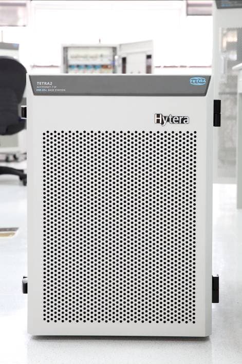
Click to zoom
Application Details
- Equipment Class
- TNB - Licensed Non-Broadcast Station Transmitter
- Date of Grant
- Sep 29, 2015
- Application Purpose
- Original Equipment
- Date of Application
- Sep 29, 2015
- Equipment Note
- TETRA Digital base station
- Frequency Range
- 854.00000000 - 869.00000000
- Company
- Hytera Mobilfunk GmbH
- Country
- Germany
Documents & Files
Document Text
Text extracted from the exhibit documents filed with the FCC. Open a document above to read the original.
Users Manual
DIB-R5 advanced Digital Integrated Base Station Operation Manual ACCESSNET ® -T IP 90DIBR5advancedOM02 - 1.0© 2014 Hytera Mobilfunk GmbH Read the instructions thoroughly prior to performing any tasks! Keep these instructions for reference. Subject to change without notice. Data without tolerance limits is not binding. ACCESSNET and all derivatives are registered trademarks of Hytera Mobilfunk GmbH. HYT and Hytera are registered trademarks of Hytera Communications Corporation Limited. Hytera Mobilfunk GmbH Fritz-Hahne-Straße 7 D-31848 Bad Münder Germany Telephone: +49 (0)5042 / 998-0 Fax: +49 (0)5042 / 998-105 E-mail: [email protected] Internet: www.hytera-mobilfunk.com DIB-R5 advanced 2Operation Manual 90DIBR5advancedOM02 - 1.0 Table of contents 1 Notes on the document..................................................................................................7 1.1 Objectives of the document...........................................................................................7 1.2 Intended audience of the document.............................................................................7 1.3 Qualification of the personnel.......................................................................................7 1.4 Reading and navigation aids in the document ...........................................................8 1.5 Figures and special notations used..............................................................................8 1.5.1 Figures used.....................................................................................................................8 1.5.2 Special notations..............................................................................................................8 1.5.2.1 Operating procedures.......................................................................................................9 1.5.2.2 Safety instructions used.................................................................................................... 9 1.5.2.3 General instructions used...............................................................................................10 1.5.2.4 Text formatting used.......................................................................................................10 1.6 Further applicable documents....................................................................................11 1.7 Support information.....................................................................................................12 2 Safety regulations.........................................................................................................13 2.1 Intended use..................................................................................................................13 2.2 Safety measures...........................................................................................................13 2.2.1 Authorized personnel......................................................................................................14 2.2.2 Electromagnetic compatibility.........................................................................................14 2.2.3 Notes on the electrical system........................................................................................15 2.3 Safety and responsibility.............................................................................................15 2.4 Safety markings............................................................................................................15 2.4.1 Safety markings on the product......................................................................................15 2.4.2 Safety markings on transport boxes...............................................................................15 2.4.2.1 Safety marking "Fragile".................................................................................................16 2.4.2.2 Safety marking "Transport Upright"................................................................................16 2.4.2.3 Safety marking "Keep dry"..............................................................................................17 3 Product description......................................................................................................19 3.1 Characteristics of the DIB-R5......................................................................................26 3.2 Components..................................................................................................................27 3.2.1 Connection and control panel.........................................................................................28 3.2.1.1 On/off switch...................................................................................................................29 3.2.1.2 Connection panel............................................................................................................29 3.2.1.3 GNSS splitter..................................................................................................................31 Table of contents DIB-R5 advanced 3Operation Manual 90DIBR5advancedOM02 - 1.0 3.2.2 V AC voltage supply..........................................................................................................31 3.2.2.1 AC Power Distribution Module (APDM)..........................................................................31 3.2.2.2 Power Supply Unit (PSU) including Power Supply Module (PSM).................................33 3.2.3 V DC voltage supply..........................................................................................................35 3.2.4 Divider Unit (DIU)............................................................................................................37 3.2.4.1 RX FILTER.....................................................................................................................38 3.2.4.2 Passive Divider Unit (PDU) ‒ only in case of a CHU exp…
Text truncated - open the document above for the full version.
Users Manual
FCC Warning Any Changes or modifications not expressly approved by the party responsible for compliance could void the user’s authority to operate the equipment. This device complies with part 15 of the FCC Rules. Operation is subject to the following two conditions: (1) This device may not cause harmful interference, and (2) this device must accept any interference received, including interference that may cause undesired operation. This equipment complies with FCC radiation exposure limits set forth for an uncontrolled environment. This equipment should be installed and operated with minimum distance 250cm between the radiator& your body. These products can operations in uncontrolled RF exposure Environments. In order to comply with the FCC RF exposure requirements, the antenna installation must comply with following: Users must be fully aware of the hazards of the exposure and able to exercise control over their RF exposure to qualify for the higher exposure limits. In order to comply with the FCC RF exposure requirements, the antenna installation must comply with following: The base station antenna must be installed so as to provide a minimum separation distance of 250cm between the antenna and persons within the area. This antenna should with gain less than 8dBi, VSWR≤1.5:1, ZO=50ohms) IC Warning This device complies with Industry Canada RSS 119 standard (s). Operation is subject to the following two conditions: (1) this device may not cause interference, and (2) this device must accept any interference,including interference that may cause undesired operation of the device. Le présentappareilestconforme aux CNR d'IndustrieCanadaapplicables aux appareils radio exempts de licence. L'exploitationestautorisée aux deux conditions suivantes: (1) l'appareil ne doit pas produire de brouillage, et (2) l'utilisateur de l'appareildoit accepter tout brouillageradioélectriquesubi, mêmesi le brouillageest susceptible d'encompromettre le fonctionnement. IC Radiation Exposure Statement: This equipment complies with IC RF radiation exposure limits set forth for an uncontrolled environment. This equipment should be installed and operated with minimum distance 250cm between the radiator & your body. IC exposition aux radiations: Cet équipement est conforme avec IC les limites d'exposition aux rayonnements définies pour un contrôlé environnement. Cet émetteur ne doit pas être co-localisés ou fonctionner en conjonction avec une autre antenne ou émetteur. Cetéquipementdoitêtreinstallé et utilisé avec un minimum de 250cm de distance entre le radiateur et votre corps. Any Changes or modifications not expressly approved by the party responsible for compliance could void the user’s authority to operate the equipment. In order to comply with the IC RF exposure requirements, the antenna installation must comply with following: The base station antenna must be installed so as to provide a minimum separation distance of 250cm between the antenna and persons within the area. This antenna should with gain less than 8dBi, VSWR≤1.5:1, ZO=50ohms)
Attestation Statements
Hytera Mobilfunk GmbH Add: Fritz-Hahne-Str. 7 Bad Muender Germany 31848 Tel: +49(0)5042998373 Fax: +49(0)5042998305 Justification Letter DATE: 2015-08-20 FEDERAL COMMUNICATIONS COMMISSIONS Authorization and Evaluation Division 7435 Oakland Mills Road Columbia, MD 21046 FCC ID: ZW4DIB5800 Model number: DIB-R5 To whom it may concern: We, Hytera Mobilfunk GmbH , acknowledge that this device will not be marketed to USA users with the frequency band which is not allowed by rule part 90.and it is a violation of FCC rules if this device is operated on unauthorized frequencies inside the U.S.A. We, Hytera Mobilfunk GmbH , acknowledge this equipment meets the requirements of FCC Rules, Parts 90.203 (e) and (g) as applicable. Programming of this product's transmit frequencies can be performed ONLY by the manufacturer or by service or maintenance personnel. The operator cannot program transmit frequencies using the equipment's external operation. Sincerely, Signature: Joern von Haefen Director Hardware Development
Cover Letter(s)
Hytera Mobilfunk GmbH Add: Fritz-Hahne-Str.7,31848BadMuender, Germany Tel: +49(0)5042998373Fax:+49(0)5042998305 FCCConfidentialAuthorization Date:20 15-08-20 FEDERfiLCOMMIJNICATIONS COMMISSION Authorization and Evaluation Division 7435OaklandMillsRoad Columbia,MD21046 Subject:ConfidentialityRequestregarding application forcertiticationofFCCID: ZW4DIB5800 InaccordancewithSections 0.457and0.459oftheCommission‘sRules,Hytera Mobilfunk GmbH,herebyrequestslong-termconfidentialtreatmentofinformation accornpanying thisappiicationasoutlinedbelow: •Block Diagram •Schematics •OperationDescription •Partlist As weilasshort-term confidentialtreatmentofinformationaccompanyingthis application as outlined below: •InternalPhotos •User‘sManual •ExternalPhotos •TestSet-upPhotos The above materialscontainproprietary and confidential information notcustomariiy releasedtothepublic.Thepublicdisclosure ofthesematerialsprovidesunjustified benefitstoitscompetitors in the market. Sincerely, Signature: / o.b. (i.A.) JoernvonHaefen Head ofDepartmentBasestationPlatform QA-FR-172-A Director Hardware Development Tune up procedure
External Photos
EXHIBIT B - EUT EXTERNAL PHOTOGRAPHS Compact: EUT –Back 1 View EUT –Back 2 View EUT –Front 1 View EUT –Front 2 View EUT –Side 1 View EUT –Side 2 View EUT –Top View Advanced EUT –Back 1 View EUT –Back 2 View EUT –Front 1 View EUT –Front 2 View EUT –Side View EUT –Top View
ID Label/Location Info
EXHIBIT A - FCC ID LABELING AND LOCATION FCC ID Label Proposed FCC ID Label Location The label shown shall be permanently affixed at a conspicuous location on the device and be readily visible to the user at the time purchase (Labeling requirements per 2.925)
Internal Photos
EXHIBIT C - EUT INTERNAL PHOTOGRAPHS EUT –ABU Unit View EUT –ABU Alarm Board Top View EUT –ABU Alarm Board Bottom View EUT –EIB BoardTop View EUT –EIB Board Bottom View EUT –ATC Top View EUT –ATC Bottom View EUT –ATC Side View EUT –ATC Side View EUT –ATC Side View EUT –ATC Side View EUT –BSCU Unit View EUT –CUMB Board Top View EUT –CUMB Board Bottom View EUT –GNSS Board Top View EUT –GNSS Board Bottom View EUT –MCB Board Top View EUT –MCB Board Bottom View EUT –MCB Board Top Uncover View EUT –MCB Board Bottom Uncover View EUT –CHU Unit View EUT –BCB Board Top View EUT –BCB Board Bottom View EUT –DPA View EUT- PDA Board Top View EUT –PDA Board Bottom View EUT –LPS Board Top View EUT –LPS Board Bottom View EUT –DIU RX-Filter Unit View EUT –DIU Duplex Unit View EUT –ADB Active DIU Board Top View EUT –ADB Active DIU Board Bottom View EUT –FAN View EUT –FANU View EUT –FMCB Board Top View EUT –FMCA Board Bottom View EUT ICB Board Top View EUT –ICB Bottom View EUT –APDU View
RF Exposure Info
Bay Area Compliance Laboratories Corp. (Dongguan) Report No.: RDG150803003-00A FCC Part 90 Page 7 of 31 FCC§1.1307 (b) (1) & §2.1091- MAXIMUM PERMISSIBLE EXPOSURE (MPE) Applicable Standard According to subpart 1.1307 (b)(1), 2.1091 systems operating under the provisions of this section shall be operated in a manner that ensures the public is not exposed to RF energy level in excess of the communication guidelines. Limits for General Population/Uncontrolled Exposure Frequency Range (MHz) Electric Field Strength (E) (V/m) Magnetic Field Strength (H) (A/m) Power Density (S) (mW/cm 2 ) Averaging Time |E|, |H| or S (minutes) 0.3-1.34 614 1.63 *100 30 1.34-30 824/f 2.19/f *180/f 2 30 30-300 27.5 0.073 0.2 30 300-1,500 f/1500 30 1,500-100,000 1.0 30 f = frequency in MHz * = Plane-wave equivalent power density Result Calculated Formulary: Predication of MPE limit at a given distance S = 2 4R PG π S = power density (in appropriate units, e.g. mW/cm2) P = power input to the antenna (in appropriate units, e.g., mW). G = power gain of the antenna in the direction of interest relative to an isotropic radiator, the power gain factor, is normally numeric gain. R = distance to the center of radiation of the antenna (appropriate units, e.g., cm) Frequency (MHz) Antenna Gain Conducted Power Evaluation Distance (cm) Power Density (mW/cm 2 ) MPE Limit (mW/cm 2 ) (dBi) (numeric) (dBm) (mW) 854.0125 8 6.31 45 31623 250 0.25 0.57 To comply with FCC RF exposure requirements, a minimum separation distance of 250 cm is required between the antenna and persons. Result: Compliance
Test Report
Note: This test report is prepared for the customer shown above and for the device described herein. It may not be duplicated or used in part without prior written consent from Bay Area Compliance Laboratories Corp. (Dongguan). This report is valid only with a valid digital signature. The digital signature may be available only under the Adobe software above version 7.0. FCC PART 90 TEST REPORT For Hytera Mobilfunk GmbH Fritz-Hahne-Str 7 D-31848 Bad Muender Germany FCC ID: ZW4DIB5800 Report Type: Original Report Product Type: TETRA Digital base station Test En gineer: Dean Liu Re port Number: RDG150803003-00A Re port Date: 2015-08-26 Reviewed B y: Sula Huang RF Leader Test Laboratory: Bay Area Compliance Laboratories Corp. (Dongguan) No.69 Pulongcun, Puxinhu Industrial Zone, Tangxia, Dongguan, Guangdong, China Tel: +86-769-86858888 Fax: +86-769-86858891 www.baclcorp.com.cn Bay Area Compliance Laboratories Corp. (Dongguan) Report No.: RDG150803003-00A FCC Part 90 Page 2 of 31 TABLE OF CONTENTS GENERAL INFORMATION ....................................................................................................................................... 3 PRODUCT DESCRIPTION FOR EQUIPMENT UNDER TEST (EUT) ..................................................................................... 3 OBJECTIVE ................................................................................................................................................................... 3 RELATED SUBMITTAL(S)/GRANT(S) ............................................................................................................................. 3 TEST METHODOLOGY .................................................................................................................................................. 3 TEST FACILITY ............................................................................................................................................................. 3 SYSTEM TEST CONFIGURATION .......................................................................................................................... 4 DESCRIPTION OF TEST CONFIGURATION ...................................................................................................................... 4 EQUIPMENT MODIFICATIONS ....................................................................................................................................... 4 SUPPORT EQUIPMENT LIST AND DETAILS .................................................................................................................... 4 EXTERNAL I/O CABLE .................................................................................................................................................. 4 TEST CONFIGURATION BLOCK DIAGRAM .................................................................................................................... 4 BLOCK DIAGRAM OF TEST SETUP ................................................................................................................................ 5 SUMMARY OF TEST RESULTS ............................................................................................................................... 6 FCC§1.1307 (b) (1) & §2.1091- MAXIMUM PERMISSIBLE EXPOSURE (MPE) .................................................... 7 APPLICABLE STANDARD .............................................................................................................................................. 7 RESULT ........................................................................................................................................................................ 7 FCC §2.1046 & §90.205- RF OUTPUT POWER ........................................................................................................ 8 APPLICABLE STANDARD .............................................................................................................................................. 8 TEST PROCEDURE ........................................................................................................................................................ 8 TEST EQUIPMENT LIST AND DETAILS ........................................................................................................................... 8 TEST DATA .................................................................................................................................................................. 8 FCC §2.1046, §90.210& §90.221- ADJACENT CHANNEL POWER .................................................................... 10 APPLICABLE STANDARD ............................................................................................................................................ 10 TEST PROCEDURE ...................................................................................................................................................... 10 TEST EQUIPMENT LIST AND DETAILS ......................................................................................................................... 10 TEST DATA ................................................................................................................................................................ 10 FCC §2.1049 & §90.209, §90.210§90.691 – OCCUPIED BANDWIDTH & EMISSION MASK ......................... 15 APPLICABLE STANDARD ............................................................................................................................................ 15 TEST PROCEDURE ...................................................................................................................................................... 16 TEST EQUIPMENT LIST AND DETAILS ......................................................................................................................... 16 TEST DATA ...............................................................................................…
Text truncated - open the document above for the full version.
Test Setup Photos
EXHIBIT D - TEST SETUP PHOTOGRAPHS Transmitting Radiated Emissions Below 1 GHz– Front View (AC Source) Transmitting Radiated Emissions Below 1 GHz– Rear View (AC Source) Transmitting Radiated Emissions Below 1 GHz– Front View (With ATC) Transmitting Radiated Emissions Below 1 GHz– Rear View (With ATC) Transmitting Radiated Emissions Below 1 GHz– Front View (DC Source) Transmitting Radiated Emissions Below 1 GHz– Rear View (DC Source) Transmitting Radiated Emissions Above 1 GHz– Front View (AC Source) Transmitting Radiated Emissions Above 1 GHz– Rear View (AC Source) Transmitting Radiated Emissions Above 1 GHz– Front View (ATC) Transmitting Radiated Emissions Above 1 GHz– Rear View (ATC) Transmitting Radiated Emissions Above 1 GHz– Front View (DC Source) Transmitting Radiated Emissions Above 1 GHz– Rear View (DC Source)
Contact Information
Applicant
Lutz Schacht(Director Hardware Development)
Test Firm
Bay Area Compliance Laboratories Corp. (Dongguan)John Chan
[email protected]86-769-86858888
Technical Specifications
| # | Rule Parts | Frequency Range | Power Output | Emission | Tolerance |
|---|---|---|---|---|---|
| 2 | 9 | 854 MHz - 869 MHz | 10 W | 21K4DXW | 0.1 ppm |
Other Applications from Hytera Mobilfunk GmbH

ZW4TIB500800
Dec 22, 2011TETRA Indoor Base Transceiver
Equipment Class
TNB - Licensed Non-Broadcast Station Transmitter
ZW4TIB500400
Dec 22, 2011TETRA Indoor Base Transceiver
Equipment Class
TNB - Licensed Non-Broadcast Station Transmitter