ZWIBNXT1BioNomadix Transmitter
BIOPAC Systems, Inc.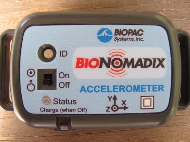
Click to zoom
Application Details
- Equipment Class
- DXT - Part 15 Low Power Transceiver, Rx Verified
- Date of Grant
- Dec 08, 2011
- Application Purpose
- Original Equipment
- Date of Application
- Dec 08, 2011
- Equipment Note
- BioNomadix Transmitter
- Frequency Range
- 2402.00000000 - 2481.00000000
- Company
- BIOPAC Systems, Inc.
- Country
- United States
Documents & Files
Document Text
Text extracted from the exhibit documents filed with the FCC. Open a document above to read the original.
Users Manual
User Guide for BioNomadix Transmitter (BN- TX) and BioNomadix Receiver (BN-RX) The BioNomadix Hardware Guide describes how to connect and set up the BioNomadix Accelerometer Transmitter/Receiver module for use with an MP150 System, Isolated Power Supply, (IPS100C) and details applications and uses for the MP System. All specifications are subject to change without notice. Rev. 1.1 11.22.2011 This manual supersedes all previous manuals BIOPAC Systems, Inc. 42 Aero Camino, Goleta, CA 93117 Tel (805) 685-0066 | Fax (805) 685-0067 www.biopac.com B IONOMADIX BN-ACCL3 MODULE BioNomadix Accelerometry X, Y, Z — Wireless Physiology The BioNomadix Tri-axial Accelerometer (BN-ACCL3) is a broad spectrum acceleration measurement system. The transmitter can be attached to any part of the subject's body to measure three-axis acceleration associated with movement in that particular location. The system comes factory preset to support an operational range of ±16 G, with a maximum system bandwidth of 400 Hz. Ranges can be set to as low as ±2 G with bandwidths as low as 3 Hz. The system can also be configured to act as a "tap detector," detect either single or double taps. In this mode, the system can act as an event recorder for self-report. When "double-tapped," for example, the system will output a pulse to precisely mark the time location of the observed event. In Acceleration measurement mode, the BN-ACCL3 will output X, Y and Z acceleration values on three associated channels. The system is very well suited for mobile applications. The system can measure the acceleration of gravity (static) for tilt-sensing and can also measure very fast-changing, dynamic acceleration resulting from rapid movement or impact. The BioNomadix Accelerometer module is capable of recording three independent X, Y and Z channels. 2 BioNomadix BN-ACCL3 Hardware User Guide Setup Overview 1. Setup the BioNo madix ACCL3 Transmitter (BN-TX) with subject. 2. Setup the BioNomadix ACCL3 Receiver (BN-RX). 3. Setup the software. Hardware Setup The BioNomadix ACCL3 Transmitter and Receiver unit are shipped as a matched pair and must always be used as a pair (see serial number and ID sync options). Up to 16 channels per BioNomadix system can be monitored simultaneously, returning data quality equal to standard BIOPAC MP modules. Normal operating range between transmitter and receiver is 10 meters line of sight in standard laboratory environments. BioNomadix Transmitter Setup 1. Secure the Transm itter module on Subject, (i.e. with a strap, or inside a BioNomadix shirt pocket). For optimum results, the BioNomadix Custom Sport Shirt is recommended. This specially-designed shirt is made of a lightweight material with numerous “pockets” for housing multiple transmitters. 2. Set the power switch on the BioNomadix Transmitter to ON. The Status light will flash sequences based upon connectivity and battery life. Single blinks every half second indicates that the transmitter and receiver are not communicating. 3. Double blinks occurring every two seconds indicate successful pairing and normal operation between transmitter and receiver. Controls ID: Press to illuminate Status light of matching Receiver unit. On/Off: Power switch for the transmitter. The transmitter power must be turned OFF for charging. Status: Solid amber when battery power is low. Approximately one hour of operation remains after light turns amber, full-charge with BN-BAT-CGR battery charger typically requires one hour. BioNomadix Receiver BEFORE BEGINNING: Decide whether one or both available channels will be used. (If using only one channel, set “X” to ON and “Y” and “Z” to OFF) Set channel slider to correct position. Attach Receiver unit to the right side of the MP150 unit, or the left side of the IPS100C. The Status light will turn green when communicating with transmitter. Set desired channel options on the Receiver module. www.biopac.com 3 Accelerometer Receiver unit controls: Wireless antenna input Receiver LED: Steady green when paired with transmitter. Blinks amber once per 4 BioNomadix BN-ACCL3 Hardware User Guide second when communication is interrupted. Input Signals: X, Y & Z “X” Assigns the input signals for channels 1-4. “Y” Assigns the input signals for channels 5-8 “Z” Assigns the input signals for channels 9-12. On/Off Enables or disables module channels: “X” channels 1-4, “Y” channels 5-8, Z channels 9-12. Transmitter Battery Life Transmitter battery life is described below as a change of color in the sequence of LED flashes. LED Color Pattern Charge % green green green green 75% - 100% yellow green green green 50% - 75% yellow yellow green green 25% - 50% yellow yellow yellow green 5% - 25% yellow yellow yellow yellow < 5% System Setup Connect the BioNomadix Receiver to the right side of the MP150, and then turn on the MP150 power button. Data acquisition to MP150 will proceed as programmed. Transmitter Characteristics If the paired signal is interrupted due to electrical interference or a subject wandering out of range, the most recently-acquired data point to the MP150 will be retained, with normal wireless transmission continuing once communication is reestablished. See BioNomadix Operational Range and Characteristics on page 6. BioNomadix Accelerometer Module Specs BioNomadix BN-ACCL3 (Consists of BN-TX and BN-RX) Signal type: G (X, Y, Z) Bandlimits Max: Factory preset: Filter Options: Alternative signal: ±2, ±4, ±8 or ±16 G ± 16 G at 400 Hz LP DC to 3.13 Hz LP up to 400 Hz LP (in power of 2 steps) Tap Event Mark Mode (replaces G) Noise (resolution): X: 5 mg rms, Y: 6 mg rms, Z: 9 mg (rms) (±2 G scale at 400 Hz LP) Signal range: Selectable: ±2, ±4, ±8 or ±16 G Output Voltage range: ±10 V (receiver output) Transmitter type & rate Type: Ultra-low power, 2.4 GHz bi-directional digital RF transmitter Operational range: 10 meters (line-of-sight) typical in standard laboratory setups. See Operational Range and Characteristics on page 6. Transmitte…
Text truncated - open the document above for the full version.
Attestation Statements
Septembers, 2011 CETCB 114 Olinda Drive Brea, CA 92823 Gentlemen: This is a letter of authorization to accept Compatible Electronics, Inc., specifically including the employees of Compatible Electronics, as an Agent for filO-l1 AC Systems, Inc., 42 A,ero Cainino, Groieta, CA 93.1.17, f°r a period of one year, to sign applications before the Commission on our behalf, to make representations to you on our behalf, and to receive and exchange data between our company and the Commission in connection with certification of the following BIOPAC product: BN-X Wireless .transmitter/receiver under FCC Docket Number 20780 and General Docket Number 80-284 pursuant to Part 15 of FCC Rules and Regulations. Please also accept this letter as an attestation that neither BIOPAC nor any of its officers, directors, or persons holding 5% or more of the outstanding stock or snares, voting or non-voting, have been denied federal benefits under section 5301 of the Anti-Drug-Abuse act of 1988,21 U.S.C. 853(a). In addition, BIOPAC will notify the Federal Communications Commission if, at any time, the situation changes causing BIOPAC to be denied federal benefits. If you have any further questions or need additional information, please feel free to give me a call at (805) 685-0066. Sincerely, ' -'"-7 Alan Macy R&D Director BIOPAC Systems, Inc.
Attestation Statements
BIOPAC Systems, In Septembers. 2011 Compatible Electronics TCB 114 Olinda Drive Brea, California 92823 Subject: TCB application submittal Gentlemen: We, BIOPAC Systems, Inc., would like to declare that the applications being submitted for the devices with FCC IDs: ZWIBNXTl and ZWIBNXRl, have not been submitted to another TCB or FCC for certification. If you have any questions, please do not hesitate to contact us at (805) 685-0066. Sincerely, Alan Macy R&D Director BIOPAC Systems, Inc.
Cover Letter(s)
Systems, Inc. Septembers, 2011 Compatible Electronics TCB 114 Olinda Drive Brea, California 92823 Subject: Request for withholding from public disclosure the schematics, block diagrams, and operational description pursuant to an application for certification Gentlemen: We, BIOPAC Systems, Inc., would like to request that all schematics, block diagrams, and operational descriptions submitted with the application for certification be withheld from public disclosure as per Section 0.459 of FCC Rules. This request is made under the provisions of Section 0.457 (d) of the Commission's Rules, and Section 552 (b)(4) of the Freedom of Information Act. These sections authorize the withholding from public inspection, those materials which would be privileged as a matter of law if retained by the person submitting them, and materials which would not customarily be released to the public by that person. If you have any questions, please do not hesitate to contact us at (805) '685-006(5; Sincerely, ' r VA Alan Macy R&D Director BIOPAC Systems, Inc.
Cover Letter(s)
Correspondence by Project Project Number: Correspondence NumberMemo ZWIBNXT1-1 1) Please provide additional information regarding the type of modulation that is used by the device. Response: The EUT uses FSK Modulation 2) The Information to User statement is not included in the user manual. Please provide a new manual with the statement included. Response: The owner’s manual has been revised to include this statement. 3) The schematics provided do not have all the components that are on the device. Specifically, the internal photos show many components between U3 and the antenna that are not included on the schematics. Please provide corrected schematics. Response: The schematics have been revised Correspondence NumberMemo ZWIBNXT1-1 1) Please provide additional information regarding the type of modulation that is used by the device. Response: The EUT uses FSK Modulation 2) The Information to User statement is not included in the user manual. Please provide a new manual with the statement included. Response: The owner’s manual has been revised to include this statement. 3) The schematics provided do not have all the components that are on the device. Specifically, the internal photos show many components between U3 and the antenna that are not included on the schematics. Please provide corrected schematics. Response: The unit was retested because the client provided the wrong version. The new test report with data and photos of the new version have been uploaded.
Test Report
Report Number: B11129D1 FCC Part 15 Subpart B and C, Section 15.205, 15.209 and 15.249 Test Report BioNomadix Transmitter Model: BN-TX Brea Division 114 Olinda Drive Brea, CA 92823 (714) 579-0500 Agoura Division 2337 Troutdale Drive Agoura, CA 91301 (818) 597-0600 Silverado Division 19121 El Toro Road Silverado, CA 92676 (949) 589-0700 Lake Forest Division 20621 Pascal Way Lake Forest, CA 92630 (949) 587-0400 Page 1 of 16 FCC PART 15 SUBPART B and C TEST REPORT for BIONOMADIX TRANSMITTER MODEL: BN-TX Prepared for BIOPAC SYSTEMS, INC. 42 AERO CAMINO SANTA BARBARA, CALIFORNIA 93117 Prepared by:_____________________ DAVID TRAN Approved by:____________________ KYLE FUJIMOTO COMPATIBLE ELECTRONICS INC. 114 OLINDA DRIVE BREA, CALIFORNIA 92823 (714) 579-0500 DATE: NOVEMBER 30, 2011 REPORT APPENDICES TOTAL BODY A B C D E PAGES 16 2 2 2 13 29 64 This report shall not be reproduced except in full, without the written approval of Compatible Electronics. Report Number: B11129D1 FCC Part 15 Subpart B and C, Section 15.205, 15.209 and 15.249 Test Report BioNomadix Transmitter Model: BN-TX Brea Division 114 Olinda Drive Brea, CA 92823 (714) 579-0500 Agoura Division 2337 Troutdale Drive Agoura, CA 91301 (818) 597-0600 Silverado Division 19121 El Toro Road Silverado, CA 92676 (949) 589-0700 Lake Forest Division 20621 Pascal Way Lake Forest, CA 92630 (949) 587-0400 Page 2 of 16 TABLE OF CONTENTS Section / Title PAGE GENERAL REPORT SUMMARY 4 SUMMARY OF TEST RESULTS 4 1. PURPOSE 5 2. ADMINISTRATIVE DATA 6 2.1 Location of Testing 6 2.2 Traceability Statement 6 2.3 Cognizant Personnel 6 2.4 Date Test Sample was Received 6 2.5 Disposition of the Test Sample 6 2.6 Abbreviations and Acronyms 6 3. APPLICABLE DOCUMENTS 7 4. DESCRIPTION OF TEST CONFIGURATION 8 4.1 Description of Test Configuration – Emissions 8 4.1.1 Cable Construction and Termination 8 5. LISTS OF EUT, ACCESSORIES AND TEST EQUIPMENT 9 5.1 EUT and Accessory List 9 5.2 Emissions Test Equipment 10 6. TEST SITE DESCRIPTION 11 6.1 Test Facility Description 11 6.2 EUT Mounting, Bonding and Grounding 11 6.3 Facility Environmental Characteristics 11 7. TEST PROCEDURES 12 7.1 RF Emissions 12 7.1.1 Conducted Emissions Test 12 7.1.2 Radiated Emissions (Spurious and Harmonics) Test 13 7.1.3 RF Emissions Test Results 15 8. CONCLUSIONS 16 Report Number: B11129D1 FCC Part 15 Subpart B and C, Section 15.205, 15.209 and 15.249 Test Report BioNomadix Transmitter Model: BN-TX Brea Division 114 Olinda Drive Brea, CA 92823 (714) 579-0500 Agoura Division 2337 Troutdale Drive Agoura, CA 91301 (818) 597-0600 Silverado Division 19121 El Toro Road Silverado, CA 92676 (949) 589-0700 Lake Forest Division 20621 Pascal Way Lake Forest, CA 92630 (949) 587-0400 Page 3 of 16 LIST OF APPENDICES APPENDIX TITLE A Laboratory Accreditations and Recognitions B Modifications to the EUT C Additional Models Covered Under This Report D Diagram, Charts, and Photos Test Setup Diagram Antenna and Amplifier Factors Radiated Emissions Photos E Data Sheets LIST OF FIGURES FIGURE TITLE 1 Conducted Emissions Test Setup 2 Plot Map And Layout of Radiated Test Site – 3 Meters Report Number: B11129D1 FCC Part 15 Subpart B and C, Section 15.205, 15.209 and 15.249 Test Report BioNomadix Transmitter Model: BN-TX Brea Division 114 Olinda Drive Brea, CA 92823 (714) 579-0500 Agoura Division 2337 Troutdale Drive Agoura, CA 91301 (818) 597-0600 Silverado Division 19121 El Toro Road Silverado, CA 92676 (949) 589-0700 Lake Forest Division 20621 Pascal Way Lake Forest, CA 92630 (949) 587-0400 Page 4 of 16 GENERAL REPORT SUMMARY Compatible Electronics Inc. generates this electromagnetic emission test report, which is an independent testing and consulting firm. The test report is based on testing performed by Compatible Electronics personnel according to the measurement procedures described in the test specifications given below and in the "Test Procedures" section of this report. The measurement data and conclusions appearing herein relate only to the sample tested and this report may not be reproduced without the written permission of Compatible Electronics, unless done so in full. This report must not be used to claim product endorsement by NVLAP, NIST or any other agency of the U.S. Government. Device Tested: BioNomadix Transmitter Model: BN-TX S/N: ACCL311007000111 Product Description: See Expository Statement Modifications: The EUT was not modified in order to meet the specifications. Customer: BIOPAC Systems, Inc. 42 Aero Camino Santa Barbara, California 93117 Test Date(s): 11/28/2011 – 11/29/2011 Test Specifications: Emissions requirements CFR Title 47, Part 15, Subpart B and Subpart C, Sections 15.205, 15.209, and 15.249 Test Procedure: ANSI C63.4 Test Deviations: The test procedure was not deviated from during the testing. SUMMARY OF TEST RESULTS TEST DESCRIPTION RESULTS 1 Conducted RF Emissions 150 kHz to 30 MHz This test was not performed because the EUT operates on battery power only and cannot be plugged into the AC public mains. 2 Radiated RF Emissions 10 kHz to 25000 MHz (Transmitter, Receiver, and Digital Portion) Complies with the Class B limits of CFR Title 47, Part 15, Subpart B; and Subpart C, sections 15.205, 15.209, and 15.249. Report Number: B11129D1 FCC Part 15 Subpart B and C, Section 15.205, 15.209 and 15.249 Test Report BioNomadix Transmitter Model: BN-TX Brea Division 114 Olinda Drive Brea, CA 92823 (714) 579-0500 Agoura Division 2337 Troutdale Drive Agoura, CA 91301 (818) 597-0600 Silverado Division 19121 El Toro Road Silverado, CA 92676 (949) 589-0700 Lake Forest Division 20621 Pascal Way Lake Forest, CA 92630 (949) 587-0400 Page 5 of 16 1. PURPOSE This document is a qualification test report based on the Electromagnetic Interference (EMI) tests performed on the BioNomadix Transmitter, Model: BN-TX. The Emissions measurements were performed according to the measurement procedure described in ANSI C63.4. The tests were performed in order to determine whether the electromagnetic …
Text truncated - open the document above for the full version.
Contact Information
Applicant
Alan Macy(R&D Manager)
Technical Contact
Compatible Electronics, Inc.Kyle Fujimoto
[email protected]714-579-0500
114 Olinda Drive · Brea, California · United States
Test Firm
Compatible Electronics, Inc.Michael Christensen
Technical Specifications
| # | Rule Parts | Frequency Range | Power Output |
|---|---|---|---|
| 1 | 15C | 2.40 GHz - 2.48 GHz | - |
Other Applications from BIOPAC Systems, Inc.
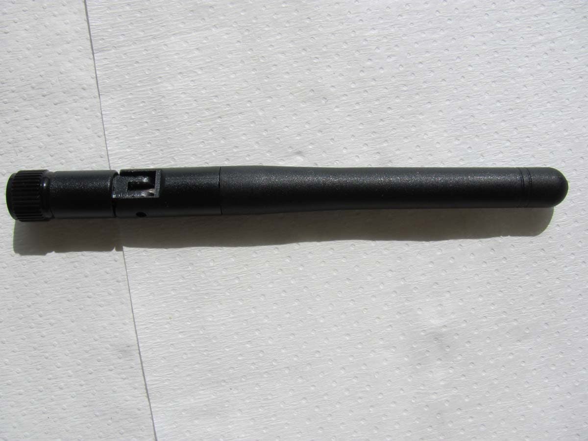
ZWIBNXR1
Dec 08, 2011BioNomadix Receiver
Equipment Class
DXT - Part 15 Low Power Transceiver, Rx Verified