FCCID.CO- FCC ID Database
HomeCompaniesEquipment ClassesSearch

© 2026 FCC ID Database. All rights reserved.

AboutContactData sourced from FCC public records
  1. Home/
  2. Audyssey Laboratories Inc./
  3. ZWSAUDWMSB01

ZWSAUDWMSB01Wireless Media Speaker

Audyssey Laboratories Inc.
Wireless Media Speaker - FCC ID ZWSAUDWMSB01 - Audyssey Laboratories Inc.
Click to zoom

Application Details

Equipment Class
DXX - Part 15 Low Power Communication Device Transmitter
Date of Grant
Jul 11, 2012
Application Purpose
Original Equipment
Date of Application
Jul 11, 2012
Equipment Note
Wireless Media Speaker
Frequency Range
2402.00000000 - 2480.00000000
Company
Audyssey Laboratories Inc.
Country
United States

Documents & Files

Select a file to view

Users Manual

↗

Cover Letter(s)

↗
↗

External Photos

↗

ID Label/Location Info

↗

Internal Photos

↗

Test Report

↗

Test Setup Photos

↗

Document Text

Text extracted from the exhibit documents filed with the FCC. Open a document above to read the original.

Users Manual

Wireless Speakers Quick Start Guide Please get the latest information and full product manual from our website at audyssey.com/support. 23 TOUR THE WIRELESS SPEAKERSIN THE BOX Wireless Speakers Power Supply Netzteil Fuente de alimentación eléctrica Alimentation électrique Alimentatore 電源ケーブル 3.5 mm Audio Cable 3,5-mm-Audiokabel Cable de audio de 3,5 mm Câble audio 3,5 mm Cavo audio 3,5 mm 3.5 mmオーディオケーブル Speaker Interconnect Cable Lautsprecherkabel Cable de interconexión de los altavoces Câble d’interconnexion des haut-parleurs Cavo di collegamento diffusori スピーカー相互接続ケーブル FRONT BACK PAIR PAIR Power LED Bluetooth LED 3.5 mm Audio Input Jack 3.5 mm Headphone Output Power Cable Plug Volume Control & Standby Knob Speaker Interconnect Cable Jacks Bluetooth Pairing Button 52 Connect your speakers to each other with the supplied Speaker Interconnect Cable. Verbinden Sie die Lautsprecher mithilfe des mitgelieferten Lautsprecherverbindungskabels miteinander. Conecte entre sí los altavoces mediante el cable de interconexión suministrado. Connectez les haut-parleurs à l’aide du câble d’interconnexion des haut-parleurs fourni. Collegare tra loro i diffusori utilizzando l’apposito cavo fornito. 各スピーカーを付属のスピーカー相互接続ケーブルで接続します。 Подсоедините динамики друг с другом с помощью входящего в комплект поставки соединительного кабеля для динамиков. STEP 1 CONNECT YOUR SPEAKERS Connect the Power Supply to the Power Supply Jack on the back of the Audyssey Wireless Speakers. Plug the Power Supply into a power outlet and confirm the Power LED on the front of the right speaker is solid red. Schließen Sie das Netzteil an die Stromversorgungsbuchse an der Rückseite der Audyssey Wireless-Lautsprecher an. Schließen Sie das Netzteil an eine Steckdose an, und vergewissern Sie sich, dass die Betriebs-LED an der Vorderseite des rechten Lautsprechers rot leuchtet. Conecte la fuente de alimentación eléctrica al conector para alimentación eléctrica de la parte trasera del Altavoz Wireless Audyssey. Enchufe la fuente de alimentación en una toma de corriente eléctrica y compruebe que el indicador LED de encendido de la parte delantera del altavoz derecho esté iluminado de forma continua en color rojo. Connectez l’alimentation électrique à la prise d’alimentation électrique à l’arrière du Haut-parleur Wireless Audyssey. Branchez l’alimentation électrique à une prise murale, et assurez-vous que le voyant d’alimentation placé sur la face avant du haut-parleur de droite reste allumé en rouge. Collegare l’alimentatore alla presa di alimentazione sul retro del Diffusore Wireless Audyssey. Inserire l’alimentatore in una presa elettrica e verificare che il LED di alimentazione sul diffusore destro si accenda fisso in rosso. 電源ケーブルをAudyssey Wireless Speaker背面の電源ケーブルコネクターに接続します。 電源ケーブルを電源コンセントに接続して、右側スピーカー正面の電源LEDが赤色に点灯していることを確認 します。 Подсоедините источник питания к разъему источника питания на задней панели динамиков Audyssey с функцией Wireless. Подключите источник питания к розетке. При этом индикатор на передней панели правого динамика должен непрерывно гореть красным цветом. STEP 2 PLUG IN SPEAKERS 67 Press the Wireless Speaker Volume Knob to switch your speakers from Standby (solid red Power LED) to On (solid green Power LED). Drücken Sie den Wireless-Lautsprecher-Lautstärkeregler, um die Lautsprecher vom Standby-Modus (rot leuchtende Betriebs-LED) in den eingeschalteten Modus (grün leuchtende Betriebs-LED) zu schalten. Presione el mando de volumen del altavoz Wireless para hacer que los altavoces pasen del modo en espera (indicador LED de encendido de forma continua en color rojo) a estar encendidos (indicador LED de encendido de forma continua en color verde). Appuyez sur le bouton de contrôle du volume du Haut-parleur Wireless pour passer les haut-parleurs du mode Veille (voyant d’alimentation rouge fixe) au mode Marche (voyant d’alimentation vert fixe). Premere la manopola volume del diffusore Wireless per accendere i diffusori che passeranno dallo stato standby (LED rosso fisso) allo stato acceso (LED verde fisso). Wirelessスピーカー]ボリュームノブを押して、スピーカーをスタンバイ(電源に点灯)からオン(電源に点灯)に切 り替えます。 Нажмите ручку громкости динамиков с функцией Wireless для перевода динамиков из режима ожидания (непрерывно горит красный индикатор) в рабочее положение (непрерывно горит зеленый индикатор). STEP 3 TURN YOUR SPEAKERS ON PAIR STEP 4 PAIR YOUR SPEAKERS Press the Pairing Button (labeled PAIR) on the back of the right speaker. The speakers will beep twice and the green Bluetooth LED on the back of the right speaker will begin flashing. This indicates that the speakers are ready to pair to your device. Drücken Sie die Kopplungstaste (mit PAIR beschriftet) an der Rückseite des rechten Lautsprechers. Die Lautsprecher piepen zweimal und die grüne Bluetooth-LED an der Rückseite des rechten Lautsprechers beginnt zu blinken. Dies weist darauf hin, dass die Lautsprecher zum Koppeln mit dem Gerät bereit sind. Presione el botón de emparejamiento (que lleva el rótulo “PAIR”) situado en la parte trasera del altavoz derecho. Los altavoces emitirán un pitido dos veces y el indicador LED de Bluetooth de color verde situado en la parte trasera del altavoz derecho empezará a titilar, lo que indica que los altavoces están listos para ser emparejados con el dispositivo elegido. Appuyez sur le bouton de liaison (le bouton PAIR) placé à l’arrière du haut-parleur droit. Les haut-parleurs émettent deux bips sonores, et le voyant Bluetooth vert à l’arrière du haut-parleur droit se met à clignoter, indiquant que les haut-parleurs sont prêts à être liés au dispositif. Premere il tasto di accoppiamento (etichettato PAIR) sul retro del diffusore destro. I diffusori emetteranno due segnali acustici e il LED verde Bluetooth sul retro del diffusore destro inizierà a lampeggiare a indicare che sono pronti per l’accoppiamento con il dispositivo. 右側スピーカー背面のペアリングボタン(PAIR)を押します。 スピーカーから応答音が2回鳴り、右側スピ ーカー背面の緑色のBluetooth LEDが点滅を開始します。これで、スピーカーとご使用のデバイスをペア リングできます。 Нажмите кнопку сопряжения (с марк…

Text truncated - open the document above for the full version.

Cover Letter(s)

Ausyssey Laboratories Inc. PHOENIX TEST-LAB GmbH Product Certification Königswinkel 10 D 32825 Blomberg Date: 07.07.2012 Authority to Act as an Agent We declare that the following representative (agent) Name Mark Wen Position General Manager Company Name Most Technology Service Co., Ltd. Address No.5, 2 nd Langshan Road, North District, Hi-Tech Industrial Park, Nanshan, Shenzhen, Guangdong, China Tel / Fax 86-755-86170306/86-755-86170310 E-Mail [email protected] to act on our behalf on all matters concerning the application and documents submitted to PHOENIX TEST-LAB for product certification below Product Name Audyssey Wireless Media Speakers Model Name AUD020004000102 Brand Name AUDYSSEY We also authorize BZT – TCP Certification GmbH, Ms.Wanida Patthanavoj (address: Hermann - Loens - Weg 6, 15859 Storkow b. Berlin Germany) to process the application. Yours sincerely, Signatory Name Luis Lopez Position Program Manager Company Name Audyssey Laboratories Inc Address 350 S.Figueroa Street Suite 233 Los Angeles CA 90071 Tel / Fax 2136254300/2136254383 E-Mail [email protected] In case of FCC, we certify that we are not subject to a denial of Federal benefits, that include FCC benefits, pursuant to Section 5301 of the Anti-Drug Abuse Act of 1988, 21 U.S.C. §862 because of a conviction for possession or distribution of a controlled substance.

Cover Letter(s)

Audyssey Laboratories Inc. Federal Communications Commission Equipment Authorization Branch 7435 Oakland Mills Road Columbia, MD 21046 Request for Confidentiality Company name: Audyssey Laboratories Inc FCC ID: ZWSAUDWMSB01 FCC Part 15 Certification Gentlemen, Pursuant to 47 CFR 0.457(d)(1)(ii) and 0.459 we hereby requests permanent confidentiality of the following documents for the subject application: Exhibit Type Description X Schematics All circuitry of devices and component values X Block Diagrams Details of device showing the frequency of all oscillators Note: Exhibit types that are commonly held confidential are: (1) Schematics, (2) Block Diagrams, (3) Bill Of Materials, (4) Operational Descriptions. Any exhibit NOT granted confidentiality is viewable on the FCC website as soon as a grant is issued. These documents contain detailed system and equipment description and related information about the product which we considers to be proprietary, confidential and a custom design and otherwise would not release to the general public. Since the design is a basis from which future technological products will evolve, we consider that this information would be of benefit to its competitors and that the disclosure of the information in these documents would give competitors an unfair advantage in the market. Yours sincerely, Signatory Name Luis Lopez Position Program Manager Company Name Audyssey Laboratories Inc. Address 350 S.Figueroa Street Suite 233 Los Angeles CA 90071 Tel / Fax 2136254300/2136254383 E-Mail [email protected] X Operational Description Description of the circuit functions

External Photos

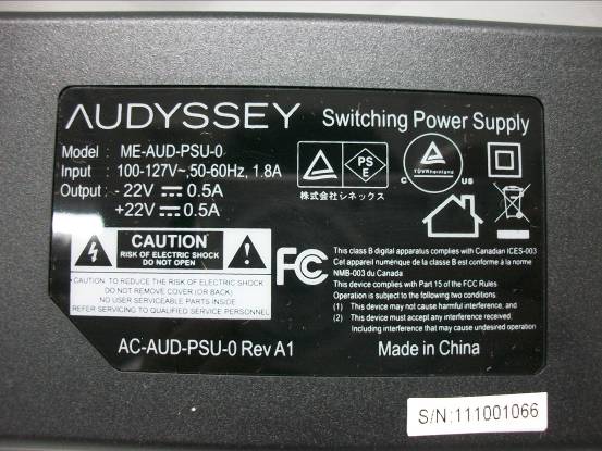
FRONT VIEW OF EUT BACK VIEW OF EUT BOTTOM VIEW OF EUT TOP VIEW OF EUT LEFT VIEW OF EUT RIGHT VIEW OF EUT ENTIRE VIEW OF SAMPLE ENTIRE VIEW OF SAMPLE VIEW PHOTO OF AC Adapter

ID Label/Location Info

United States and International patents applied for Wireless Media Speakers Model No.: AUD020004000102 Designed in USA, Made in China AC-CCSBT-LBL-RAT-US Rev A1 FCC ID:ZWSAUDWMSB01 IC:9951A-AUDWMSD01 Mo

Internal Photos

INTERNAL PHOTO OF SAMPLE – 1 INTERNAL PHOTO OF SAMPLE – 2 INTERNAL PHOTO OF SAMPLE –3 INTERNAL PHOTO OF SAMPLE –4 INTERNAL PHOTO OF SAMPLE –5 INTERNAL PHOTO OF Adapter – 1 INTERNAL PHOTO OF Adapter – 2 INTERNAL PHOTO OF Adapter – 3

Test Report

FCC 47 CFR PART 15 SUBPART C TEST REPORT For Applicant: Audyssey Laboratories Inc Address: 350 S.Figueroa Street Suite 233 Los Angeles CA 90071 Product Name: Audyssey Wireless Media Speakers Model Name: AUD020004000102, AUD02000400010X(X can be “0-9”) Brand Name: AUDYSSEY FCC ID: ZWSAUDWMSB01 Report No.: MTE/EAH/D12060741 Date of Issue: Jun. 12, 2012 Issued by : Most Technology Service Co., Ltd. Address : No.5, Langshan 2nd Road, North District, Hi-tech Industrial Park, Nanshan, Shenzhen, Guangdong, China Tel : 86-755-8617 0306 Fax : 86-755-8617 0310 The report consists 45 pages in total. It may be duplicated completely for legal use with the approval of the applicant. It should not be reproduced except in full, without the written approval of our laboratory. The client should not use it to claim product endorsement by MOST. The test results in the report only apply to the tested sample. The test report shall be invalid without all the signatures of testing engineers, reviewer and approver. FCC ID: ZWSAUDWMSB01 Report No.: MTE/EAH/E12060741 Page 2 of 45 TABLE OF CONTENTS 1. VERIFICATION OF CONFORMITY.......................................................................................... 4 2. GENERAL INFORMATION....................................................................................................... 5 2.1 Product Information ................................................................................................................ 5 2.2 Objective ................................................................................................................................ 6 2.3 Test Standards and Results .................................................................................................... 6 2.4 Environmental Conditions....................................................................................................... 6 2.5 MEASUREMENT UNCERTAINTY ......................................................................................... 6 3. TEST FACILITY........................................................................................................................ 7 3.1TEST FACILITY....................................................................................................................... 7 3.2 Test Conditions ....................................................................................................................... 7 3.3 Channel List ........................................................................................................................... 8 3.4 Description of Test Modes ...................................................................................................... 8 3.5 Table of Parameters of Text Software Setting......................................................................... 9 3.6 FCC PART 15.205 RESTRICTED BANDS OF OPERATIONS............................................. 10 4. SETUP OF EQUIPMENT UNDER TEST.................................................................................11 4.1 SUPPORT EQUIPMENT .......................................................................................................11 4.2 TEST EQUIPMENT LIST...................................................................................................... 12 5. 47 CFR Part 15C 15.249 Requirements................................................................................. 13 5.1 Spurious Emission Test ........................................................................................................ 13 5.1.1 Requirement...................................................................................................................... 13 5.1.2 Test Description ................................................................................................................. 14 5.1.3 Test Description ................................................................................................................. 15 5.1.5 Test Result .....................................................................................................................16 5.2 Band Edge............................................................................................................................ 28 5.2.1 Requirement...................................................................................................................... 28 5.2.2 Test Description ................................................................................................................. 28 5.2.3Test Result.......................................................................................................................... 28 5.3 LINE CONDUCTED EMISSION TEST................................................................................. 34 5.3.1. LIMITS OF LINE CONDUCTED EMISSION TEST........................................................... 34 5.3.2. BLOCK DIAGRAM OF TEST SETUP............................................................................... 34 5.3.3. PRELIMINARY PROCEDURE OF LINE CONDUCTED EMISSION TEST ...................... 35 5.3.4. FINAL PROCEDURE OF LINE CONDUCTED EMISSION TEST .................................... 35 5.3.5. Test result ......................................................................................................................... 35 5.3.5. TEST RESULT OF LINE CONDUCTED EMISSION TEST .............................................. 36 FCC ID: ZWSAUDWMSB01 Report No.: MTE/EAH/E12060741 Page 3 of 45 5.4 20 dB Bandwidth .................................................................................................................. 38 5.4.1 Definition ........................................................................................................................... 38 5.4.2 Block Diagram Of Test Setup ............................................................................................ 38 5.4.3 Test Result..........................................................…

Text truncated - open the document above for the full version.

Test Setup Photos

CONDUCTED TEST SETUP CE TEST SETUP RE TEST SETUP

Contact Information

Applicant

Luis A Lopez(Program Manager)
[email protected]2136254300Fax: 2136254383

Test Firm

Most Technology Service Co., Ltd.Mark Wen
[email protected]86-755-86170306Fax: 86-755-86170310

Technical Specifications

#Rule PartsFrequency RangePower Output
115C2.40 GHz - 2.48 GHz-
Confidentiality
Long Term

Other Applications from Audyssey Laboratories Inc.
LOWER EAST SIDE AUDIO DOCK AIR - FCC ID ZWSLESAIRD01 - Audyssey Laboratories Inc.
ZWSLESAIRD01

LOWER EAST SIDE AUDIO DOCK AIR

Nov 28, 2011

Equipment Class

DTS - Digital Transmission System