ZXZMCWA60AMPLIFIER
Dayton Audio Division of Parts Express
Click to zoom
Application Details
- Equipment Class
- DTS - Digital Transmission System
- Date of Grant
- Feb 01, 2015
- Application Purpose
- Original Equipment
- Date of Application
- Feb 01, 2015
- Equipment Note
- AMPLIFIER
- Frequency Range
- 2412.00000000 - 2462.00000000
- Country
- United States
Documents & Files
Document Text
Text extracted from the exhibit documents filed with the FCC. Open a document above to read the original.
Users Manual
60 WATT CLASS D PLATE AMPLIFIER with W BLUETOOTH 4.0 aptX Model: MCWA60 User Manual (3) REMOTE CONTROL POWER – Toggles the power state of the amplifier from STANDBY to ON. When the unit is ON, the indicator LED will illuminate BLUE. When the unit is in STANDBY, the indicator LED will illuminate RED. (Note: Turning OFF the rear power switch will turn power completely off to the unit, disabling the remote.) VOLUME – Adjusts the volume level of the amplifier. If the source device has a volume control in itself, set the volume to full then control the volume with the MCWA60 volume control. As the volume increases or decreases the blue indicator LED will flash. When volume is at min or MAX, the blue indicator LED will not flash. MUTE – Press once to temporarily mute the amplifier. The blue indicator LED will flash slowly while the MCWA60 is muted. PLAY/PAUSE – Press once to play or pause program audio in Bluetooth mode only. PREVIOUS/SKIP – Press to move to the beginning of the current song or advance to the next song in Bluetooth mode only. AUX 1/2 – Press once to switch to the corresponding analog input on the amplifier. The blue indicator LED will flash once. OPTICAL – Press once to switch to the S/PDIF Toslink input on the amplifier. The blue indicator LED will flash once. BLUETOOTH – Press to switch to and pair with the Bluetooth input on the amplifier. The blue indicator LED will flash once. WiFi – Press once to switch to and pair with the Wi-Fi input on the amplifier. The blue indicator LED will flash once. OPERATION Once you have completed installation of the MCWA60 into your project it is best to test the system using a known operating source component connected to one of the analog inputs. The default state of the amplifier at power-ON is to enter STANDBY mode; use the remote to turn the power on and select an input to begin listening. PHYSICAL CONNECTION Connect an audio source to any of the three external inputs. Permanent connection of sources including CD/BD/DVD players, television/satellite/cable boxes, game consoles, and other sources are best supported using the OPTICAL or AUX 1 (RCA) inputs, while portable music players and PCs are best supported by the AUX 2 (3.5mm) input. WIRELESS CONNECTION – BLUETOOTH ® Bluetooth connectivity provides an easy, wireless connection for a personal audio device such as a tablet or mobile phone. The MCWA60 utilizes a Bluetooth 4.0 transceiver featuring aptX ® decoding for CD quality audio, and also supports legacy A2DP, AVRCP, HFP, and HSP Bluetooth audio profiles. This is a Class II Bluetooth receiver with a range of approximately 10 meters. To pair your device, put the phone or tablet into pairing mode. Press the Bluetooth button on the remote control. Press “scan“ on the phone or tablet and select the device labeled “DABTA“. The blue indicator LED will illuminate brightly to show pairing was successful. Note: The remote control functions PREVIOUS, SKIP, PLAY, and PAUSE are only available for use in Bluetooth mode. WIRELESS CONNECTION – Wi-Fi The Wi-Fi connection in the MCWA60 operates using the same principles as your home Wi-Fi internet connection; however, the MCWA60 does not connect to your home Wi-Fi or to the internet. Instead, it creates its own Wi-Fi network, which your source device connects to. The Wi-Fi connection provides an easy, wireless connection for a personal audio device such as a smartphone, tablet, or PC. Note: Each MCWA60 is assigned a unique Wi-Fi serial Identifier. This number can be found on the amplifier’s face (same as serial number). Open the Wi-Fi settings in your smartphone, tablet, or PC. Press the Wi-Fi button on the remote control. Scan for Wi-Fi networks and select the network labeled DAWAXXX, where “XXX“ is a unique string of numbers assigned to the Wi-Fi module. Note: In most cases your smartphone, tablet, or PC will lose internet WiFi connectivity while connected to and streaming audio to the MCWA60 amplifier. STANDBY MODE The MCWA60 will automatically switch to standby mode if no signal is sensed for 15 minutes. When a signal is sensed, the MCWA60 will “wake-up“ automatically and begin to operate. Power consumption in standby mode is less than 0.5W. ® Power: Inputs: Outputs: Frequency response: Operating power: Standby power: Bluetooth module: Bluetooth Audio Profiles: Bluetooth range: Wi-Fi: Signal to noise ratio: 2 x 30 Watts RMS (Class D) AUX 1: 2 x RCA, AUX 2: 3.5mm Stereo, S/PDIF Optical: Toslink 30" lead with 0.205" disconnects, Dual 5-way binding posts, RCA LFE Output (80 Hz Xover) 45-20,000 Hz 90 ~ 230 Vac, 50/60 Hz, 80Watts <0.5Watts V4.0 + EDR, Class II aptX, A2DP, AVRCP, HFP, and HSP 10 meters 2.4 GHz, Apple AirPlay® compatible >95dB Specificati ons and design subject to modificati on without notic e This equipment has been tested and found to comply with the limits for a Class B digital device, pursuant to Part 15 of the FCC Rules. These limits are designed to provide reasonable protection against harmful interference in a residential installation. This equipment generates uses and can radiate radio frequency energy and, if not installed and used in accordance with the instructions, may cause harmful interference to radio communications. However, there is no guarantee that interference will not occur in a particular installation. If this equipment does cause harmful interference to radio or television reception, which can be determined by turning the equipment off and on, the user is encouraged to try to correct the interference by one or more of the following measures: -- Reorient or relocate the receiving antenna. -- Increase the separation between the equipment and receiver. -- Connect the equipment into an outlet on a circuit different from that to which the receiver is connected. -- Consult the dealer or an experienced radio/TV technician for help. This device complies with part 15 of the FCC Rules. Operation is subject to the following two conditions:(1) This device may not cause harmf…
Text truncated - open the document above for the full version.
Cover Letter(s)
SCS-F19: Confidentiality Request Letter Page 1 of 2 Rev 3.0 775 Montague Expressway Milpitas, CA 95035 Tel: 408-526-1188 Fax: 408-526-1088 Email: [email protected] Confidentiality Request Letter Revision History Reason for Amendment (current / obsolete) From To Approved Date Initial Release (obsolete) 1.0 1.0 Nov-14-2006 Adding CFR 2.459 (obsolete) 1.0 2.0 August – 11 - 2008 Updated company template & Added text box (current) 2.0 3.0 Jan-31-2012 SCS-F19: Confidentiality Request Letter Page 2 of 2 Rev 3.0 Dayton Audio Division of Parts Express 725 Pleasant Valley Rd Springboro, Ohio 45066 USA 2014-12-26 To: Federal Communications Commission Authorization and Evaluation Division 7435 Oakland Mills Road Columbia, MD Subject: Permanent Confidentiality Request for FCC ID: ZXZMCWA60 We hereby request confidential treatment of information accompanying this application as outlined below: Block Diagram Schematics Operational Description The above materials contain trade secrets and proprietary information not customarily released to the public. The public disclosure of these materials may be harmful to the applicant and provide unjustified benefits to its competitors. The applicant understands that pursuant to Section 0.457 & 0.459 of the Rules, disclosure of this application and all accompanying documentation will not be made before the date of the Grant for this application. Sincerely, signature : name / title: Rich Taylor / Marketing Manager address: 725 Pleasant Valley Rd Springboro, Ohio 45066 USA
ID Label/Location Info
Label location 铁面板丝印 Bh4 AMP 要求: 1.烤漆黑平光(粉体)素材同B H-4 2.黑 色 丝印成白色 3. PANTONE:2945C 4.丝 印不能有偏色,偏移,毛边等现像 (5012115162) FCC ID:ZXZMCWA60
Internal Photos
WIFI Antenna BT Antenna
RF Exposure Info
FCC ID: ZXZMCWA60 1. RF EXPOSURE EVALUATION 1.1. Limits The criteria listed in the following table shall be used to evaluate the environment impact of human exposure to radio frequency (RF) radiation as specified in 1.1307(b) Limits for Maximum Permissible Exposure (MPE) f = frequency in MHz Friis transmission formula: Pd = (Pout*G)/(4*pi*r 2 ) Where Pd = power density in mW/cm 2 , Pout = output power to antenna in mW; G = gain of antenna in linear scale, Pi = 3.1416; R = distance between observation point and center of the radiator in cm Pd id the limit of MPE, 1 mW/cm 2 . If we know the maximum gain of the antenna and the total power input to the antenna, through the calculation, we will know the distance r where the MPE limit is reached. 1.2. Test Procedure Software provided by client enabled the EUT to transmit and receive data at lowest, middle and highest channel individually. FCC ID: ZXZMCWA60 1.3. Test Result of RF Exposure Evaluation Channel Frequency (MHz) Maximum Target Value (dBm) Maximum Target Value (mW) Antenna Gain (dBi) Power Density at R=20cm (mW/cm2) Limit (mW /cm 2 ) Result 802.11b 16.0 39.81 2.0 0.01255 1.0 Pass 802.11g 13.0 19.95 2.0 0.00629 1.0 Pass 802.11n (HT20) 12.0 15.85 2.0 0.00500 1.0 Pass 802.11n (HT40) 12.0 15.85 2.0 0.00500 1.0 Pass
Test Report
FCC ID: ZXZMCWA60 Keyway Testing Technology Co., Ltd. Report No. 14KWE122288F Page 1 of 47 FCC TEST REPORT for Dayton Audio Division of Parts Express AMPLIFIER Model Number: MCWA60 FCC ID: ZXZMCWA60 Prepared for : Dayton Audio Division of Parts Express Address : 725 Pleasant Valley Rd Springboro, Ohio 45066 USA Prepared by : Keyway Testing Technology Co., Ltd. Address : Baishun Industrial Zone, Zhangmutou Town, Dongguan, Guangdong, China Report No. : 14KWE122288F Date of Test : Dec 5~9, 2014 Date of Report : Dec 12, 2014 FCC ID: ZXZMCWA60 Keyway Testing Technology Co., Ltd. Report No. 14KWE122288F Page 2 of 47 TABLE OF CONTENTS Test Report Declaration Page 1. TEST SUMMARY ........................................................................................................................ 4 2. GENERAL PRODUCT INFORMATION ....................................................................................... 4 2.1. Product Function .................................................................................................................. 4 2.2. Description of Device (EUT) ................................................................................................. 4 2.3. Independent Operation Modes ............................................................................................. 5 2.4. Test Supporting System ....................................................................................................... 5 3. TEST SITES ................................................................................................................................ 6 3.1. Test Facilities ....................................................................................................................... 6 3.2. List of Test and Measurement Instruments .......................................................................... 7 4. TEST SET-UP AND OPERATION MODES ................................................................................. 8 4.1. Principle of Configuration Selection ...................................................................................... 8 4.2. Block Diagram of Test Set-up .............................................................................................. 8 4.3. Test Operation Mode and Test Software .............................................................................. 8 4.4. Special Accessories and Auxiliary Equipment ...................................................................... 8 4.5. Countermeasures to Achieve EMC Compliance ................................................................... 8 4.6. Test Environment: ................................................................................................................ 8 5. EMISSION TEST RESULTS ........................................................................................................ 9 5.1. Conducted Emission at the Mains Terminals Test ................................................................ 9 5.2. Radiated Emission Test ..................................................................................................... 12 6. 6DB OCCUPY BANDWIDTH ..................................................................................................... 27 6.1. Limits ................................................................................................................................. 27 6.2. Test setup .......................................................................................................................... 27 6.3. Test result .......................................................................................................................... 27 7. BAND EDGE COMPLIANCE TEST ........................................................................................... 34 7.1. Limits ................................................................................................................................. 34 7.2. Test setup .......................................................................................................................... 34 8. OUTPUT POWER TEST ........................................................................................................... 36 8.1. Limits ................................................................................................................................. 36 8.2. Test setup .......................................................................................................................... 36 8.3. Test result .......................................................................................................................... 36 9. POWER SPECTRAL DENSITY TEST ....................................................................................... 37 9.1. Limits ................................................................................................................................. 37 9.2. Test setup .......................................................................................................................... 37 9.3. Test result .......................................................................................................................... 37 10. ANTENNA REQUIREMENTS ................................................................................................ 40 10.1. Limits ................................................................................................................................. 40 10.2. Result................................................................................................................................. 40 11. PHOTOGRAPHS OF TEST SET-UP ..................................................................................... 41 12. PHOTOGRAPHS OF THE EUT ............................................................................................. 43 FCC ID: ZXZMCWA60 Keyway Testing Technology Co., Ltd. Report No. 14KWE122288F Page 3 of 47 Keyway Testing Technology Co…
Text truncated - open the document above for the full version.
Test Setup Photos
Conducted Emission Radiated Emission Test
Contact Information
Applicant
Brian Myers(Product Development Manager)
Test Firm
Keyway Testing Technology Co., Ltd.Jade Yang
Technical Specifications
| # | Rule Parts | Frequency Range | Power Output |
|---|---|---|---|
| 1 | 15C | 2.41 GHz - 2.46 GHz | 34.00 mW |
Other Applications from Dayton Audio Division of Parts Express
ZXZ2401A
Jan 28, 2024Speaker
Equipment Class
DSS - Part 15 Spread Spectrum Transmitter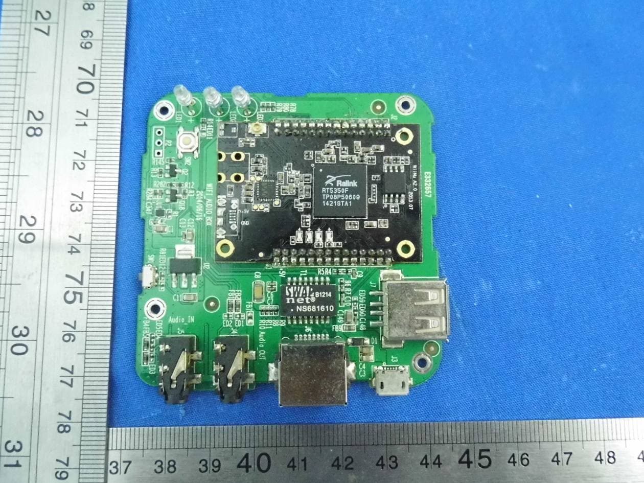
ZXZWFA02
Nov 19, 2015WiFi Multiroom Audio Adapter
Equipment Class
DTS - Digital Transmission System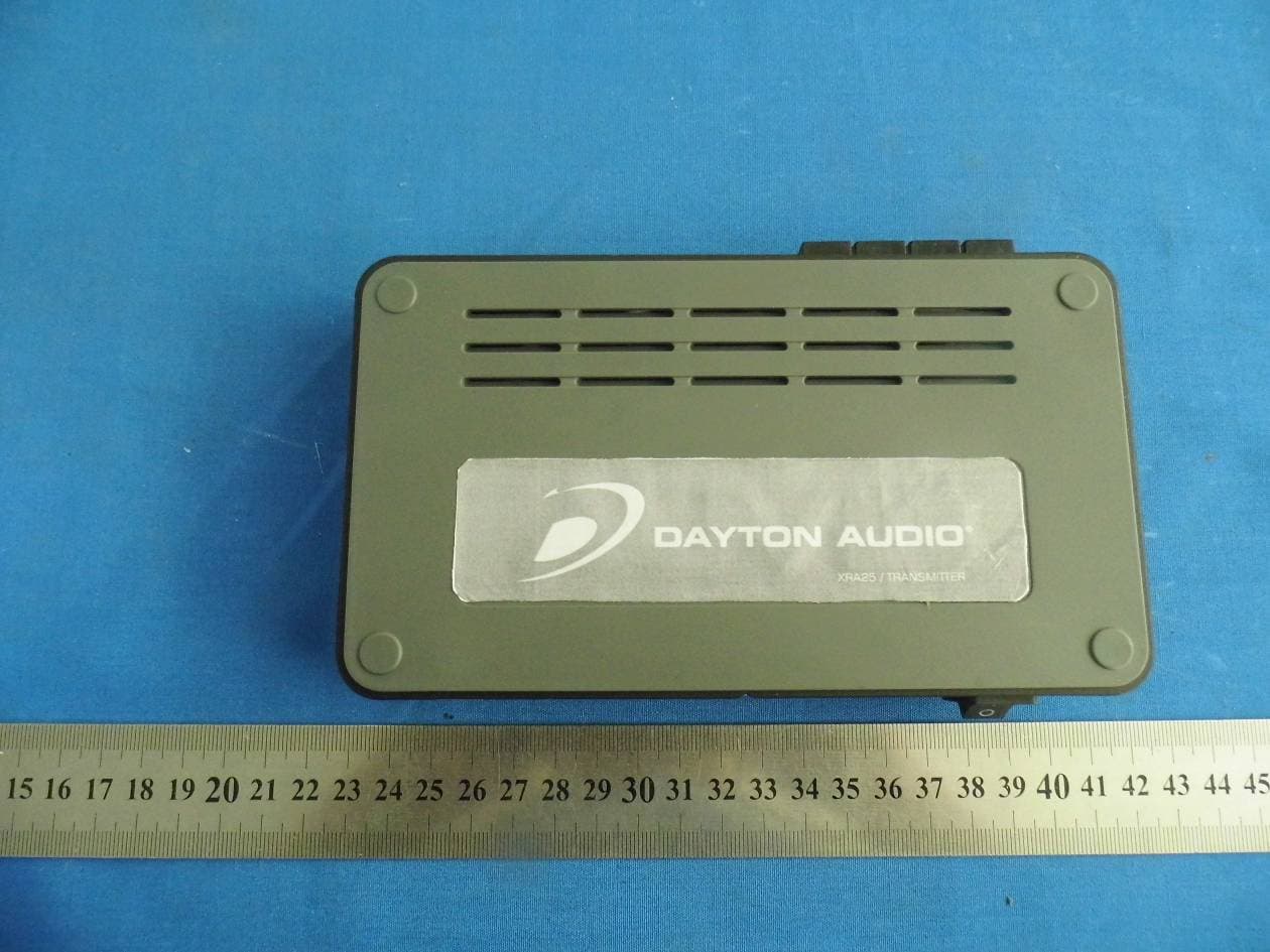
ZXZ-XRA25
Jul 28, 2014Wireless Speaker Kit with Subwoofer Output
Equipment Class
DXX - Part 15 Low Power Communication Device TransmitterZXZ-DTA-1T
Aug 29, 2011Wireless Audio Amplifier
Equipment Class
DXX - Part 15 Low Power Communication Device Transmitter