ZY2DP01UPCS DECT PHONE BASE
APROTECH CO. LTD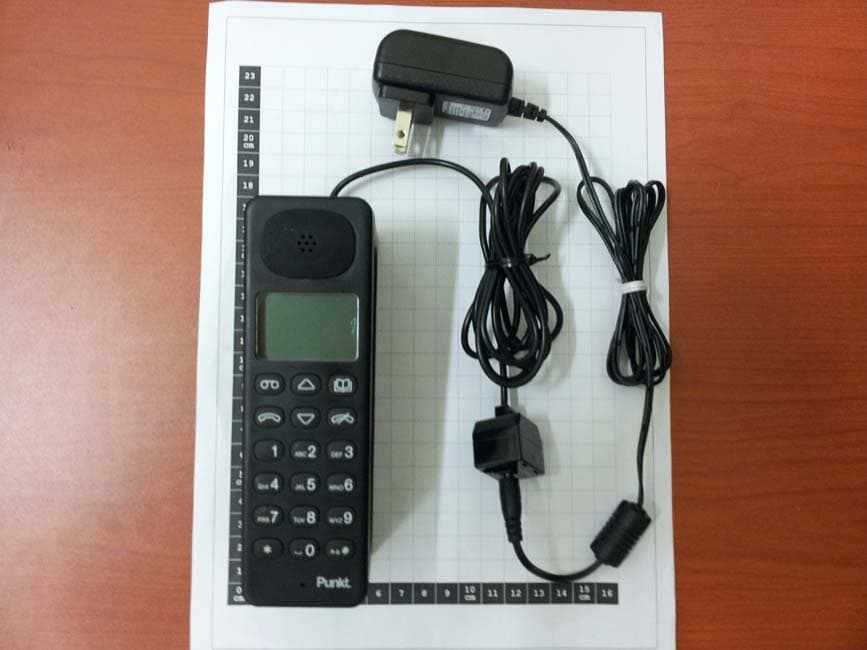
Click to zoom
Application Details
- Equipment Class
- PUB - Part 15 Unlicensed PCS Base Station
- Date of Grant
- Nov 01, 2011
- Application Purpose
- Original Equipment
- Date of Application
- Nov 01, 2011
- Equipment Note
- UPCS DECT PHONE BASE
- Frequency Range
- 1921.53600000 - 1928.44800000
- Company
- APROTECH CO. LTD
- Country
- South Korea
Documents & Files
Document Text
Text extracted from the exhibit documents filed with the FCC. Open a document above to read the original.
Users Manual
1 Remove back of phone 2 Insert batteries into the handset, then replace back 3 Insert phone cable 4 Insert power cable 5 Connect to phone and power sockets. 6 Place the handset on the base for charging 2 1 5 6 4 3 Installation A Select (/Send/Yes) B Cancel (/End/No/Backspace) (Power On/Off - hold for 5 seconds) C Scroll up and scroll down D Phone Book E Answer phone F Signal Power G Number of answer phone message(s) H Battery Power (flashes on charging, static when full) I Keypad Change language: – Press select “Handset settings” and press – Select “Language” and press – Select required language – Press to confirm. Set time/date: – Press select “Time/Date” and press – Enter time and press – Enter date and press – Press to confirm Change ringtone: – Press select sounds and press – Select ringtone and press – Press to select favorite sound – Press to confirm Display icons & function keysBasic usage of the phone E C D I H F G A C B Make a phone call: – Enter the number using the key pad – Press to start call – Press to end the call Make a phone call using the phone book: – Press to open phone book – Use to browse your contacts – Press to select the desired contact – Use to browse the phone numbers – Press to start the call – Press to end the call Hands free mode: – When in call press on handsfree to toggle on/off Volume control: – When in call press select “Volume” – Press – Press to adjust the volume. – Press or wait 3 secs to return to incall menu Enter a new contact in the phone book: – Press to open phone book – Press to select “New” – Use the keypad to enter the name, operates as backspace – Press – Press to confirm – Press to select the option you want to assign a number – Press to select – Enter the number using the keypad – Press – Press to confirm Activate/deactivate answering machine: – Press to open answer phone – Press and select “Settings” – Press – Press to toggle answering machine On/Off Listen to all new messages: – Press – Press – Press to play all Listen to a selected new message: – Press – Press – Press to browse the messages – Press to select – Press to play RL1818_Punkt Phone_Quick Guide 5.indd 11/4/10 13:39:01 DP 01 DECT Phone Quick Guide RL1818_Punkt Phone_Quick Guide 5.indd 21/4/10 13:39:06 PUNKT DP01 - DP01S: TECHNICAL, SAFETY & COMPLIANCE INFORMATION (ver 1.0) SAVE THESE INSTRUCTIONS! Important Safety Instructions! When using your telephone equipment, basic safety precautions should always be followed to reduce the risk of fire, electric shock and injury to persons, including the following: This unit is NOT waterproof. DO NOT expose it to rain or moisture. Keep batteries out of reach of children. Do not use this product near water, for example, near a bath tub, wash bowl, kitchen sink or laundry tub, in a wet basement or near a swimming pool. Avoid sources of noise and heat, such as motors, fluorescent lighting, microwave ovens, heating appliances and direct sunlight. Avoid using a telephone (other than a cordless type) during an electrical storm. There may be a remote risk of electric shock from lightning. Do not use the telephone to report a gas leak in the vicinity of the leak. Use only the power cord and batteries indicated in the “Technical information” section of this information sheet. Do not dispose of batteries in a fire. They may explode. Check with local codes for possible special disposal instructions. Do not place the handset in any charging cradle without the batteries installed and the battery cover securely in place. IMPORTANT: Because cordless phones operate on electricity, you should have at least one phone in your home that isn’t cordless, in case the power in your home goes out. Technical Information AC-DC Power Adapter Information AC-DC Adapter for the Base (DP01) and Handset Charger (DP01S) Adapter model DYS052-050070W-1 Input voltage 100-240V AC, 50/60Hz Output voltage 5.0V ; 0.7 A Use only the supplied AC adapter. Do not place the unit in direct sunlight or subject it to high temperatures. Batteries Information Rechargeable batteries (with normal use) Number of batteries 2 Battery type Ni-MH “AAA” size rechargeable batteries Capacity 1.2V, 650 mAh Talk time about 10 hours Standby time about 100 hours Time required for first charging about 16 hours Time required for the next charging cycles about 8 hours Use only 2 Ni-MH type, “AAA” size, 1.2V 650mAh rechargeable batteries, as the ones provided in this package or with identical mechanical and electrical specifications. Leave the handset located on the base unit (for DP01 model) or battery charger (for DP01S model) for 16 hours before using the DP01 handset for the first time. After that time, the batteries will be fully charged and the handset can be used to make and receive phone calls. Next charging cycles will take around 8 hours (from full discharge). Keep batteries out of reach of children. When the batteries charging level gets low, the handset beeps and shows a low battery alert; recharge the batteries. Rechargeable Battery Warning This equipment contains 2 rechargeable Nickel-Metal-Hydride (Ni-MH) batteries. Nickel is a chemical known to the state of California to cause cancer. Do not short-circuit the batteries. The batteries in this equipment may explode if disposed of in a fire. Do not charge the batteries in any charger other than the original DP01(DP01S) handsets itself. Using another charger may damage the battery or cause it to explode. CAUTION! Risk of explosion if battery is replaced by an incorrect type! Rechargeable batteries must be recycled or disposed of properly. Do not open or mutilate the batteries. Remove the batteries from the handset before shipping this product. Telephone Jack Requirements To use this phone, you need an RJ11C type modular telephone jack, which might look like the one pictured here, installed in your home. If you don’t have a modular jack, call your local phone company to find out how to get one installed. G…
Text truncated - open the document above for the full version.
Cover Letter(s)
APROTECH CO.,LTD. (201-23 Anyang-7Dong, Manan-gu, Anyang-Si, Gyeonggi-do 430-817 KOR ) Date : 2011/09/01 Timco Engineering, Inc. 849 NW State Road 45, P.O. Box 370 To whom it may concern: We, the undersigned, hereby authorize Korea Testing Laboratory, to act on our behalf in all manners relating to application for equipment authorization, including signing of all documents relating to these matters. Any and all acts carried out by Korea Testing Laboratory on our behalf shall have the same effect as acts of our own. In authorizing KTL as our agent, we still recognize that we are responsible to: a) comply with the relevant provisions of the certification program; b) make all necessary arrangements for the conduct of the evaluation, including provision for examining documentation and access to all areas, records (including internal audit reports) and personnel for the purposes of evaluation (e.g. testing, inspection, assessment, surveillance, reassessment) and resolution of complaints; c) make claims regarding certification only in respect of the scope for which certification has been granted; d) do not use our product certification in such a manner as to bring the Certification Division into disrepute and not make any statement regarding our product certification which the Certification Division may consider misleading or unauthorized; e) upon suspension or cancellation of certification, discontinue use of all advertising matter that contains any reference thereto and return any certification documents as required by the Certification Division; f) use certification only to indicate the products are certified as being in conformity with specified standards; g) endeavor to ensure that no certificate or report nor any part thereof is used in a misleading manner; h) ensure that any reference to our product certification in communication media such as documents, brochures or advertising, complies with the requirements of the Certification Division; i) keep a record of all complaints made known to the us relating to the product’s compliance with requirements of the relevant standard and to make these records available to the Certification Division when requested; j) take appropriate action with respect to such complaints and any deficiencies found in products or services that affect compliance with the requirements for certification; k) document the actions taken. This authorization is valid until further written notice from the applicant. Sincerely Yours, Signature Here Printed Name: Chung-Hwa Lee Title: Engineer REMARK: 1. This authorization letter will be sent along with your application when filing with the Certification Division. 2. Please follow the format and type it on company letterhead and send original to us.
Cover Letter(s)
Address : 201-23 Anyang-7Dong, Manan-gu, Anyang-Si, Gyeonggi-do 430-817 KOR E-MAIL : [email protected] Federal Communications Commission 7435 Oakland Mills Road Columbia, MD 21046 Attention : Equipment Authorization Branch REQUEST FOR CONFIDENTIALITY Pursuant to Sections 0.457 (d) and 0.459 of the Commission’s Rules, the Applicant hereby requests confidential treatment of some of the information accompanying this Application of FCC ID : ZY2-DP01 and as outlined below: 1. Block Diagram 2. Schematic Diagram 3. Operational description These materials contain trade secrets and proprietary information not customarily released to the public and the public disclosure of these matters might be harmful to the Applicant and provide unjustified benefits to its competitors. The Applicant understands that pursuant to Rule 0.457(d) disclosure of this Application . Sincerely, Date 09 of 09 , 2011 By: Chung-Hwa Lee Title : Engineer ============================================================
External Photos
FCCID : ZY2DP01(Base) Photographs (Exterior) <Base + Handy Configurations> FCCID : ZY2DP01(Base) Photographs (Exterior) FCCID : ZY2DP01(Base) Photographs (Exterior) FCCID : ZY2DP01(Base) Photographs (Exterior)
ID Label/Location Info
D310 FCC Label2011.11.02 Model : DP01 FCC ID : ZY2DP01 US : A2TW401BDP01 Complies with FCC Part68 Rules Telco Jack Type USOC RJ11 V : DC5V 0.7A Model : DP01H FCC ID : ZY2DP01H US : A2TW401BDP01 Complies with FCC Part68 Rules Use only with battery listed in operational manual Made in PRC
Internal Photos
FCCID : ZY2DP01(Base) Photographs (Interior) FCCID : ZY2DP01(Base) Photographs (Interior) FCCID : ZY2DP01(Base) Photographs (Interior)
RF Exposure Info
723, Haean-ro, Sa-dong, Sangnok-gu, Ansan-si, Gyeonggi-do, 426-910 KOREA Tel. : +82-31-5000-133 http://www.ktl.re.kr Fax. : +82-31-5000-149 FP-204-03-01 RF EXPOSURE INFORMATION 1. MPE Limits The limit for Maximum Permissible Exposure (MPE), specified in FCC §1.1310 is listed in Table 1. According to this rule: the criteria listed in the following tables shall be used to evaluate the environmental impact of human exposure to radio-frequency radiation. Table1. FCC LIMITS FOR MAXIMUM PERMISSIBLE EXPOSURE Frequency Range (MHz) Electric Field Strength (V/m) Magnetic Field Strength (A/m) Power Density (mW/cm 2 ) Average Time (Minutes) (A) Limits For Occupational / Control Exposures (f= frequency) 30-300 61.4 0.163 1.0 6 300-1500 ... ... ... 6 1500-100,000 ... ... ... 6 (B) Limits For General Population / Uncontrolled Exposure (f=frequency) 30-300 27.5 0.073 0.2 30 300-1500 ... ... f/1500 30 1500-100,000 ... ... 1.0 30 2. EUT INFORMATION - Applicant : APROTECH CO.,LTD. - Name : Digital Enhanced Cordless Telephone (Punkt) - Model Name : DP01 - FCC ID : ZY2DP01 - Tx Frequency Band : 1921.536 MHz ~ 1928.448 MHz 3. PROCEDURES The procedure used to determine the RF power density was based upon a calculation for determining compliance with the MPE requirements. This calculation is based on the highest EIRP possible from the system, considering maximum power and antenna gain, and considering the limit of uncontrolled exposure limit. The power density level is calculated at a distance of 20 cm. And Minimum distance is also calculated. MPE calculations are calculated under Maximum Power condition in the band. Formula P d =PG / (4πr 2 ) 723, Haean-ro, Sa-dong, Sangnok-gu, Ansan-si, Gyeonggi-do, 426-910 KOREA Tel. : +82-31-5000-133 http://www.ktl.re.kr Fax. : +82-31-5000-149 FP-204-03-01 Where, P d = Power Density (mW/cm 2 ) P= Power input to the antenna (in appropriate units, e.g., mW) G= Power gain of the antenna in the direction of interest relative to an isotropic radiator π=3.1416 r=distance between observation point and centre of the radiator (cm) 4. Calculated MPE The power density limit for General Population/Uncontrolled Exposure at each frequency is determined based on the information in Table 1. MPE calculations are calculated at the Maximum Power frequency channel. Table2. UPCS Calculated MPE Data Frequency 1924.992 MHz (3ch) Limit 1mW/cm 2 Distance (cm), R 20 cm Ant. Gain, G 1.0 dBi Conducted Power 19.13 dBm (81.85 mW) Power Density (mW/cm 2 ) 0.0205 Minimum Distance 2.86 cm 5. MPE Results Based on the above calculation for 20cm separation, the power density does not exceed FCC limit of 1mW/ cm 2 And the minimum distance satisfying the FCC limit is 2.86 cm.
Test Report
Report No.: 11-2341-032-02 Page 1 of 50 Pages 723, Haean-ro, Sa-dong, Sangnok-gu, Ansan-si, Gyeonggi-do, 426-910 KOREA Tel: +82-31-500-0133 http://www.ktl.re.kr Fax: +82-31-500-0149 FP-204-03-01 TEST REPORT 1. Applicant Name : APROTECH CO.,LTD. Address : 201-23, Anyang-Dong, Manan-Gu, Anyang-Si, Gyeonggi-Do, 430-817, Korea 2. Products Name : Digital Enhanced Cordless Telephone (Punkt) Model : DP01 (Base) Manufacturer : APROTECH CO.,LTD. 3. Test Standard/Method : FCC Part 15 Subpart D/ ANSI C63.17 4. Test Results : Positive 5. Use of Report : - 6. Date of Application : August 22, 2011 7. Date of Issue : September 19, 2011 Tested by Approved by ` Sung-kyu Cho Jeong-min Kim Telecommunication Center Engineer Telecommunication Center Manager The test results contained apply only to the test sample(s) supplied by the applicant, and this test report shall not be reproduced in full or in part without approval of the KTL in advance. Report No.: 11-2341-032-02 Page 2 of 50 Pages 723, Haean-ro, Sa-dong, Sangnok-gu, Ansan-si, Gyeonggi-do, 426-910 KOREA Tel : +82-31-500-0133 http://www.ktl.re.kr Fax: +82-31-500-0149 FP-204-03-01 TABLE OF CONTENTS 1. GENERAL INFORMATIONS .................................................................................................. 3 2. SUMMARY OF TEST RESULTS ............................................................................................ 5 3. TEST RESULTS ..................................................................................................................... 7 3.1 ANTENNA REQUIREMENTS ................................................................................................................................................. 7 3.2 DIGITAL MODULATION TECHNICS ...................................................................................................................................... 8 3.3 EMISSION BANDWIDTH ........................................................................................................................................................ 9 3.4 POWER ADJUSTMENT FOR ANTENNA GAIN ................................................................................................................... 11 3.5 RADIATED OUT OF BAND EMISSION ................................................................................................................................ 12 3.6 PEAK TRANSMIT POWER .................................................................................................................................................. 13 3.7 POWER SPECTRAL DENSITY ............................................................................................................................................ 16 3.8 AUTOMATICALLY DISCONTINUED TRANSMISSION........................................................................................................ 18 3.9 IN-BAND EMISSIONS .......................................................................................................................................................... 19 3.10 OUT-OF-BAND EMISSIONS ................................................................................................................................................ 21 3.11 CARRIER FREQUENCY STABILITY ................................................................................................................................... 28 3.12 FRAME REPETITION STABILITY ........................................................................................................................................ 29 3.13 FRAME PERIOD AND JITTER ............................................................................................................................................. 30 3.14 MONITORING TIME ............................................................................................................................................................. 31 3.15 MONITORING THRESHOLD ................................................................................................................................................ 32 3.16 MAXIMUM TRANSMIT TIME ................................................................................................................................................ 33 3.17 SYSTEM ACKNOWLEDGEMENT ........................................................................................................................................ 34 3.18 LEAST INTERFERED CHANNEL & CHANNEL CONFIRMATION ...................................................................................... 35 3.19 RANDOM WAITTING ............................................................................................................................................................ 36 3.20 MONITORING BANDWIDTH ................................................................................................................................................ 37 3.21 MAXIMUM REACTION TIME ............................................................................................................................................... 40 3.22 MONITORING ANTENNA .................................................................................................................................................... 42 3.23 DUPLEX CONNECTIONS .................................................................................................................................................... 43 3.24 ALTERNATIVE MONITORING INTERVAL FOR CO-LOCATED DEVICE ............................................................................ 44 3.25 CONDUCTED EMISSIONS...........................................................................................................................45 4. SELF DECLARATION .......................................................................................................... 47 5. TEST SET UP ....................................................................................................…
Text truncated - open the document above for the full version.
Test Setup Photos
FCC ID : ZY2DP01 Test Setup Photos
Contact Information
Applicant
Chung-Hwa Patrick Lee(Marketing Team Leader)
Test Firm
Korea Testing LaboratoryYang-hyun Kim
Technical Specifications
| # | Rule Parts | Frequency Range | Power Output |
|---|---|---|---|
| 1 | 15D | 1.92 GHz - 1.93 GHz | 100.00 mW |
Other Applications from APROTECH CO. LTD
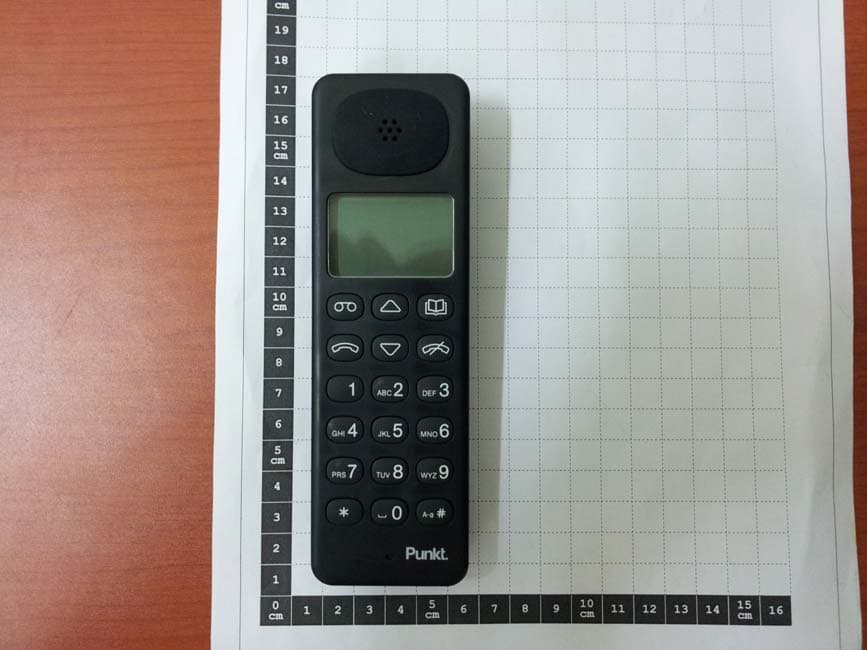
ZY2DP01H
Nov 01, 2011UPCS DECT PHONE HANDSET
Equipment Class
PUE - Part 15 Unlicensed PCS portable Tx held to ear