2A22JOTMODULES7591-01, 7591-02, 7591-04
TSI Incorporated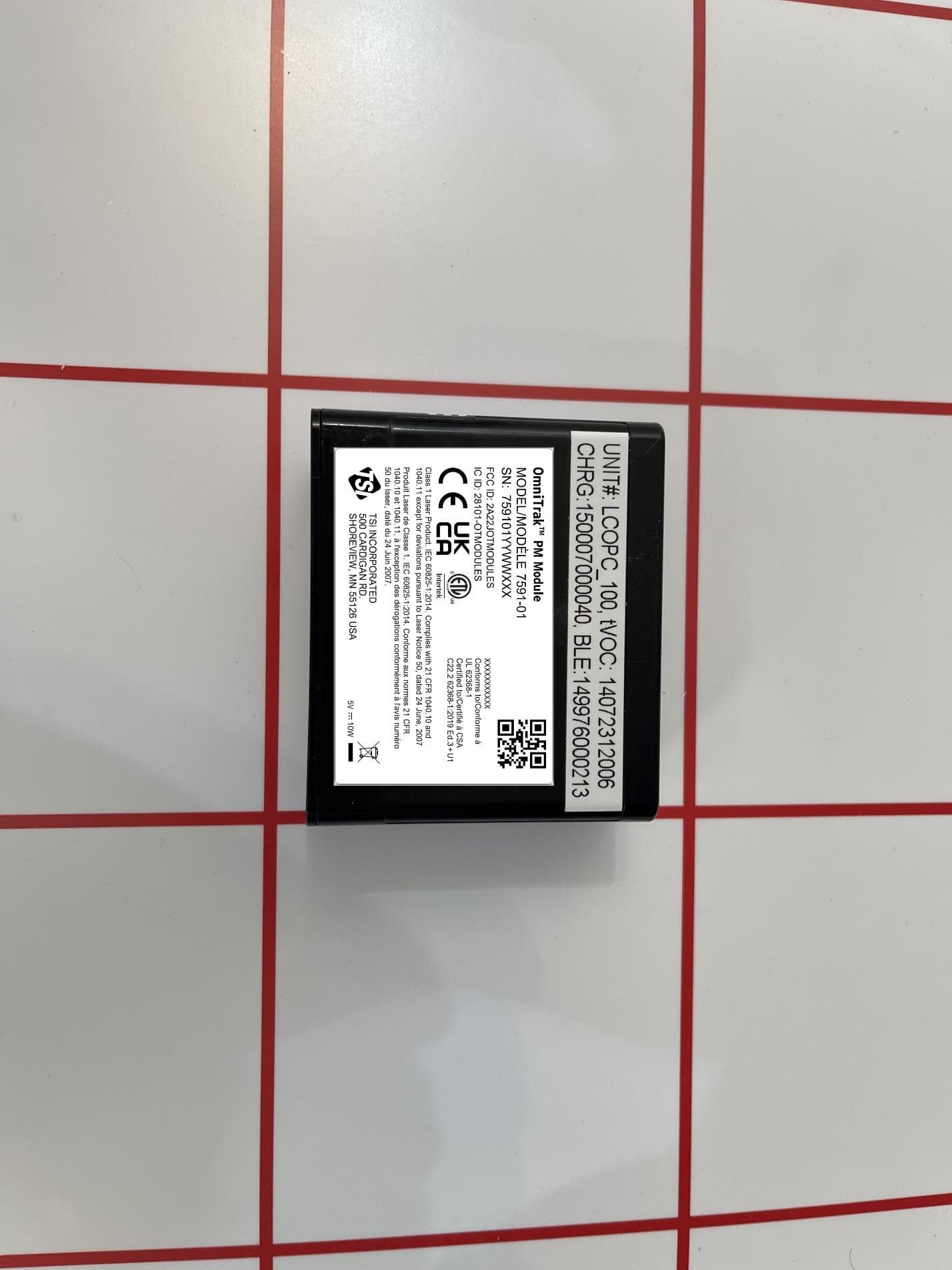
Click to zoom
Application Details
- Equipment Class
- DTS - Digital Transmission System
- Date of Grant
- Jul 13, 2023
- Application Purpose
- Original Equipment
- Date of Application
- Jul 13, 2023
- Equipment Note
- 7591-01, 7591-02, 7591-04
- Frequency Range
- 2402.00000000 - 2480.00000000
- Company
- TSI Incorporated
- Country
- United States
Documents & Files
Document Text
Text extracted from the exhibit documents filed with the FCC. Open a document above to read the original.
Users Manual
PM Module Model 7591-01 Operation Instructions 1. Power On: Hold down power button on left side of module for 1 second. 2. Power Off: Hold down power button on left side of module until you see a light sequence of green, yellow, red. That indicates module is off. 3. Charging: Plug USB-C into bottom of module and into power source. A blinking green light indicates module is charging. 4. Connecting to a Smart Station: Power on module by holding down the circle on the left for 1 second. A blue LED light will start to blink indicating Bluetooth® is on. - The module will appear in the list on the Smart Station. If not, hit Refresh. - Press desired module on screen to connect to Smart Station. A green check mark indicates a successful connection. - Press Done Now you’re ready to take measurements. The OmniTrak™ Smart Station can be used in conjunction with any OmniTrak™ Module to provide immediate feedback as to the conditions in the immediate area. Take measurements, create reports, and analyze data provided to help improve conditions. This instrument is a handheld device, not to be worn on the body, or near an individual’s head. Dispose of battery in accordance with local rules and regulations. What’s Included in the Box ▪ Device ▪ USB-C Cable NOTE: All modules, by default, are shipped in ‘Sleep Mode’ to protect the battery. It will not be possible to power on the Module, using the side button, until ‘Sleep Mode’ is disabled. To disable, plug the module into a power source and charge the module for a few minutes. This process is required only once. PM Module Model 7591-01 SpecificationsSpecifications PM Sensor Specifications Number Concentration Range0 to 3’000—#/cm³ Number Concentration Size Range NC0.50.3 to 0.5μm NC1.00.5 to 1.0μm NC2.51.0 to 2.5μm NC42.5 to 4.0μm NC104.0 to 10.0μm Number Concentration Precision for PM0.5, PM1, and PM2.5 0 to 1000 #/cm³±100#/cm³ 1000 to 3000 #/cm³±10% m.v. Number Concentration Precision for PM4, PM10 0 to 1000 #/cm³ ±250#/cm³ 1000 to 3000 #/cm³±25% m.v. Mass Concentration Range0 to 1’000—μg/m³ Number Concentration Size Range PM1.00.3 to 1.0μm PM2.50.3 to 2.5μm PM4.00.3 to 4.0μm PM10.00.3 to 10.0μm Number Concentration Precision for PM1, and PM2.5 0 to 100 μg/m³±10μg/m³ 100 to 1000 μg/m³±10% m.v. Number Concentration Precision for PM4, PM10 0 to 100 μg/m³±25μg/m³ 100 to 1000 μg/m³±25% m.v. AC and DC Power Requirements AC/DC Power SupplyAC/DC Power Supply 100 to 240 VAC, 100 to 240 VAC, 50/60 Hz, 0.3A50/60 Hz, 0.3A Device Input PowerDevice Input Power5 VDC, 2A, 10W 5 VDC, 2A, 10W Environmental/Installation Requirements Maximum AltitudeMaximum Altitude 3000 meters 3000 meters (10,000 feet)(10,000 feet) Pollution DegreePollution Degree22 Installation CategoryInstallation CategoryII Operating Operating TemperatureTemperature 5°C to 40°C5°C to 40°C Storage TemperatureStorage Temperature-20°C to 60°C-20°C to 60°C HumidityHumidity 0% - 95% 0% - 95% (non-condensing)(non-condensing) Compliance This device contains license-exempt This device contains license-exempt transmitter(s)/receiver(s) that comply with transmitter(s)/receiver(s) that comply with Innovation, Science and Economic Development Innovation, Science and Economic Development Canada’s license-exempt RSS(s). Operation is Canada’s license-exempt RSS(s). Operation is subject to the following two conditions:subject to the following two conditions: 1. This device may not cause interference.1. This device may not cause interference. 2. This device must accept any interference, 2. This device must accept any interference, including interference that may cause including interference that may cause undesired operation of the device.undesired operation of the device. Le présent appareil est conforme aux CNR Le présent appareil est conforme aux CNR d’Industrie Canada applicables aux appareils radio d’Industrie Canada applicables aux appareils radio exempts de licence. L’exploitation est autorisée exempts de licence. L’exploitation est autorisée aux deux conditions suivantes: aux deux conditions suivantes: 1. l’appareil ne doit pas produire de brouillage, et 1. l’appareil ne doit pas produire de brouillage, et 2. l’utilisateur de l’appareil doit accepter tout 2. l’utilisateur de l’appareil doit accepter tout brouillage radioélectrique subi, même si le brouillage radioélectrique subi, même si le brouillage est susceptible d’en compromettre brouillage est susceptible d’en compromettre le fonctionnement.le fonctionnement. To satisfy RF exposure requirements, this device To satisfy RF exposure requirements, this device and its antenna may be operated near a persons and its antenna may be operated near a persons body and the extremities, but must be operated body and the extremities, but must be operated with a separation distance of at least 20 cm from with a separation distance of at least 20 cm from all person’s head.all person’s head. Pour satisfaire aux exigences d’exposition RF, Pour satisfaire aux exigences d’exposition RF, cet appareil et son antenne peuvent être utilisés cet appareil et son antenne peuvent être utilisés à proximité du corps et des extrémités d’une à proximité du corps et des extrémités d’une personne, mais doivent être utilisés avec une personne, mais doivent être utilisés avec une distance de séparation d’au moins 20 cm distance de séparation d’au moins 20 cm de la tête de toute personne. de la tête de toute personne. Compliance FCC ID: FCC ID: 2A22JOTMODULES2A22JOTMODULES IC ID: IC ID: 28101-OTMODULES28101-OTMODULES This device complies with part 15 of the This device complies with part 15 of the FCC Rules. Operation is subject to the FCC Rules. Operation is subject to the following two conditions: following two conditions: 1. This device may not cause harmful interference. 1. This device may not cause harmful interference. 2. This device must accept any interference 2. This device must accept any interference received, including interference that may cause received, including interference t…
Text truncated - open the document above for the full version.
Users Manual
PM + tVOC-PID (PPM) Module Model 7591-04 Operation Instructions 1. Power On: Hold down power button on left side of module for 1 second. 2. Power Off: Hold down power button on left side of module until you see a light sequence of green, yellow, red. That indicates module is off. 3. Charging: Plug USB-C into bottom of module and into power source. A blinking green light indicates module is charging. 4. Connecting to a Smart Station: Power on module by holding down the circle on the left for 1 second. A blue LED light will start to blink indicating Bluetooth® is on. - The module will appear in the list on the Smart Station. If not, hit Refresh. - Press desired module on screen to connect to Smart Station. A green check mark indicates a successful connection. - Press Done Now you’re ready to take measurements. The OmniTrak™ Smart Station can be used in conjunction with any OmniTrak™ Module to provide immediate feedback as to the conditions in the immediate area. Take measurements, create reports, and analyze data provided to help improve conditions. This instrument is a handheld device, not to be worn on the body, or near an individual’s head. Dispose of battery in accordance with local rules and regulations. What’s Included in the Box ▪ Device ▪ USB-C Cable DISCLAIMER The tVOC measurement sensor is sensitive to radio frequency interference. Electromagnetic fields produced by items including, but not limited to, microwave ovens, Wi-Fi® routers, cellular phones, and personal communication devices, i.e., walkie-talkie, two-way radios, etc. have the potential to adversely affect the measurement. To ensure a proper measurement these devices should be TURNED OFF or placed in a mode that does not transmit. If these devices are not turned off or placed in a mode that does not transmit, the accuracy of the measurement may be compromised if these devices are located within four meters of the sensor module. NOTE: All modules, by default, are shipped in ‘Sleep Mode’ to protect the battery. It will not be possible to power on the Module, using the side button, until ‘Sleep Mode’ is disabled. To disable, plug the module into a power source and charge the module for a few minutes. This process is required only once. SpecificationsSpecifications tVOC Sensor Specifications Sensor TypePID (Photo Isonization Detector) Range0-2000 ppm Resolution0.1 ppm Accuracy+/- (5ppm + 15% displayed value) ppm Response Time< 10 seconds PM + tVOC-PID (PPM) Module Model 7591-04 PM Sensor Specifications Number Concentration Range0 to 3’000—#/cm³ Number Concentration Size Range NC0.50.3 to 0.5μm NC1.00.5 to 1.0μm NC2.51.0 to 2.5μm NC42.5 to 4.0μm NC104.0 to 10.0μm Number Concentration Precision for PM0.5, PM1, and PM2.5 0 to 1000 #/cm³±100#/cm³ 1000 to 3000 #/cm³±10% m.v. Number Concentration Precision for PM4, PM10 0 to 1000 #/cm³ ±250#/cm³ 1000 to 3000 #/cm³±25% m.v. Mass Concentration Range0 to 1’000—μg/m³ Number Concentration Size Range PM1.00.3 to 1.0μm PM2.50.3 to 2.5μm PM4.00.3 to 4.0μm PM10.00.3 to 10.0μm Number Concentration Precision for PM1, and PM2.5 0 to 100 μg/m³±10μg/m³ 100 to 1000 μg/m³±10% m.v. Number Concentration Precision for PM4, PM10 0 to 100 μg/m³±25μg/m³ 100 to 1000 μg/m³±25% m.v. AC and DC Power Requirements AC/DC Power SupplyAC/DC Power Supply 100 to 240 VAC, 100 to 240 VAC, 50/60 Hz, 0.3A50/60 Hz, 0.3A Device Input PowerDevice Input Power5 VDC, 2A, 10W 5 VDC, 2A, 10W Environmental/Installation Requirements Maximum AltitudeMaximum Altitude 3000 meters 3000 meters (10,000 feet)(10,000 feet) Pollution DegreePollution Degree22 Installation CategoryInstallation CategoryII Operating Operating TemperatureTemperature 5°C to 40°C5°C to 40°C Storage TemperatureStorage Temperature-20°C to 60°C-20°C to 60°C HumidityHumidity 0% - 95% 0% - 95% (non-condensing)(non-condensing) Compliance This device contains license-exempt This device contains license-exempt transmitter(s)/receiver(s) that comply with transmitter(s)/receiver(s) that comply with Innovation, Science and Economic Development Innovation, Science and Economic Development Canada’s license-exempt RSS(s). Operation is Canada’s license-exempt RSS(s). Operation is subject to the following two conditions:subject to the following two conditions: 1. This device may not cause interference.1. This device may not cause interference. 2. This device must accept any interference, 2. This device must accept any interference, including interference that may cause including interference that may cause undesired operation of the device.undesired operation of the device. Le présent appareil est conforme aux CNR Le présent appareil est conforme aux CNR d’Industrie Canada applicables aux appareils radio d’Industrie Canada applicables aux appareils radio exempts de licence. L’exploitation est autorisée exempts de licence. L’exploitation est autorisée aux deux conditions suivantes: aux deux conditions suivantes: 1. l’appareil ne doit pas produire de brouillage, et 1. l’appareil ne doit pas produire de brouillage, et 2. l’utilisateur de l’appareil doit accepter tout 2. l’utilisateur de l’appareil doit accepter tout brouillage radioélectrique subi, même si le brouillage radioélectrique subi, même si le brouillage est susceptible d’en compromettre brouillage est susceptible d’en compromettre le fonctionnement.le fonctionnement. To satisfy RF exposure requirements, this device To satisfy RF exposure requirements, this device and its antenna may be operated near a persons and its antenna may be operated near a persons body and the extremities, but must be operated body and the extremities, but must be operated with a separation distance of at least 20 cm from with a separation distance of at least 20 cm from all person’s head.all person’s head. Pour satisfaire aux exigences d’exposition RF, Pour satisfaire aux exigences d’exposition RF, cet appareil et son antenne peuvent être utilisés cet appareil et son antenne peuvent être utilisés à proximité du corps et des extrémités d’une …
Text truncated - open the document above for the full version.
Users Manual
tVOC-PID (PPM) Module Model 7591-02 Operation Instructions 1. Power On: Hold down power button on left side of module for 1 second. 2. Power Off: Hold down power button on left side of module until you see a light sequence of green, yellow, red. That indicates module is off. 3. Charging: Plug USB-C into bottom of module and into power source. A blinking green light indicates module is charging. 4. Connecting to a Smart Station: Power on module by holding down the circle on the left for 1 second. A blue LED light will start to blink indicating Bluetooth® is on. - The module will appear in the list on the Smart Station. If not, hit Refresh. - Press desired module on screen to connect to Smart Station. A green check mark indicates a successful connection. - Press Done Now you’re ready to take measurements. The OmniTrak™ Smart Station can be used in conjunction with any OmniTrak™ Module to provide immediate feedback as to the conditions in the immediate area. Take measurements, create reports, and analyze data provided to help improve conditions. This instrument is a handheld device, not to be worn on the body, or near an individual’s head. Dispose of battery in accordance with local rules and regulations. What’s Included in the Box ▪ Device ▪ USB-C Cable NOTE: All modules, by default, are shipped in ‘Sleep Mode’ to protect the battery. It will not be possible to power on the Module, using the side button, until ‘Sleep Mode’ is disabled. To disable, plug the module into a power source and charge the module for a few minutes. This process is required only once. SpecificationsSpecifications tVOC Sensor Specifications Sensor TypePID (Photo Isonization Detector) Range0-2000ppm Resolution0.1ppm Accuracy+/-15% displayed value Response Time< 10seconds tVOC-PID (PPM) Module Model 7591-02 AC and DC Power Requirements AC/DC Power SupplyAC/DC Power Supply 100 to 240 VAC, 100 to 240 VAC, 50/60 Hz, 0.3A50/60 Hz, 0.3A Device Input PowerDevice Input Power5 VDC, 2A, 10W 5 VDC, 2A, 10W Environmental/Installation Requirements Maximum AltitudeMaximum Altitude 3000 meters 3000 meters (10,000 feet) (10,000 feet) Pollution DegreePollution Degree22 Installation CategoryInstallation CategoryII Operating Operating TemperatureTemperature 5°C to 40°C5°C to 40°C Storage TemperatureStorage Temperature-20°C to 60°C-20°C to 60°C HumidityHumidity 0% - 95% 0% - 95% (non-condensing)(non-condensing) Compliance This device contains license-exempt This device contains license-exempt transmitter(s)/receiver(s) that comply with transmitter(s)/receiver(s) that comply with Innovation, Science and Economic Development Innovation, Science and Economic Development Canada’s license-exempt RSS(s). Operation is Canada’s license-exempt RSS(s). Operation is subject to the following two conditions:subject to the following two conditions: 1. This device may not cause interference.1. This device may not cause interference. 2. This device must accept any interference, 2. This device must accept any interference, including interference that may cause including interference that may cause undesired operation of the device.undesired operation of the device. Le présent appareil est conforme aux CNR Le présent appareil est conforme aux CNR d’Industrie Canada applicables aux appareils radio d’Industrie Canada applicables aux appareils radio exempts de licence. L’exploitation est autorisée exempts de licence. L’exploitation est autorisée aux deux conditions suivantes: aux deux conditions suivantes: 1. l’appareil ne doit pas produire de brouillage, et 1. l’appareil ne doit pas produire de brouillage, et 2. l’utilisateur de l’appareil doit accepter tout 2. l’utilisateur de l’appareil doit accepter tout brouillage radioélectrique subi, même si le brouillage radioélectrique subi, même si le brouillage est susceptible d’en compromettre brouillage est susceptible d’en compromettre le fonctionnement.le fonctionnement. To satisfy RF exposure requirements, this device To satisfy RF exposure requirements, this device and its antenna may be operated near a persons and its antenna may be operated near a persons body and the extremities, but must be operated body and the extremities, but must be operated with a separation distance of at least 20 cm from with a separation distance of at least 20 cm from all person’s head.all person’s head. Pour satisfaire aux exigences d’exposition RF, Pour satisfaire aux exigences d’exposition RF, cet appareil et son antenne peuvent être utilisés cet appareil et son antenne peuvent être utilisés à proximité du corps et des extrémités d’une à proximité du corps et des extrémités d’une personne, mais doivent être utilisés avec une personne, mais doivent être utilisés avec une distance de séparation d’au moins 20 cm de la distance de séparation d’au moins 20 cm de la tête de toute personne. tête de toute personne. Compliance FCC ID: FCC ID: 2A22JOTMODULES2A22JOTMODULES IC ID: IC ID: 28101-OTMODULES28101-OTMODULES This device complies with part 15 of the This device complies with part 15 of the FCC Rules. Operation is subject to the FCC Rules. Operation is subject to the following two conditions: following two conditions: 1. This device may not cause harmful interference. 1. This device may not cause harmful interference. 2. This device must accept any interference 2. This device must accept any interference received, including interference that may cause received, including interference that may cause undesired operation.undesired operation. Per FCC 15.21 Changes or modifications not Per FCC 15.21 Changes or modifications not expressly approved by TSI will void the product expressly approved by TSI will void the product warranty and may void the user’s authority to warranty and may void the user’s authority to operate the equipment.operate the equipment. tVOC-PID (PPM) Module Model 7591-02 4420176118 TSI Incorporated - Visit our website www.tsi.com for more information. USA Tel: +1 800 874 2811 UK Tel: +44 149 4 459200 France Tel: +…
Text truncated - open the document above for the full version.
Cover Letter(s)
2023-06-02 Federal Communications Commission Authorization and Evaluation Division 7435 Oakland Mills Road Columbia, Maryland 21046 Request for Confidentiality Letter Date: June 2, 2023 To whom it may concern, We hereby respectfully request that under the provision of 47 CFR 0.459 and 0.457(d), the documents listed below and attached with this application for certification be provided with confidential status. Exhibit Type Document Number or Name Schematics NINA-B3.SCH.11-1 Parts List NINA-B3_BOM_04-1 Any exhibit / information for which we have requested confidentiality, but which may not be accorded such treatment by the FCC, should be returned to us The above exhibits, owned solely by u-blox AG, contain trade secrets and proprietary information not customarily release to the public. The public disclosure of these materials may be harmful to u-blox AG and provide unjustified benefits to its competitors. Yours Sincerely, Request_for_C onfident iality _Letter_TSI_ FC CRequest_for_C onfident iality _Letter_TSI_ FC CRequest_for_C onfident iality _Letter_TSI_ FC CRequest_for_C onfident iality _Letter_TSI_ FC CRequest_for_C onfident iality _Letter_TSI_ FC CRequest_for_ Confident iality _Letter_TSI_ FCC Filip Kruzela Certification manager, u-blox AG u-blox AG Zürcherstrasse 68 8800 Thalwil Switzerland Phone +41 44 722 74 44 Fax +41 44 722 74 47 [email protected] [email protected]
External Photos
7591-01 External Photos
External Photos
7591-02 External Photos
External Photos
7591-04 External Photos
ID Label/Location Info
7591-01 Label and Location
ID Label/Location Info
7591-02 Label and Location
ID Label/Location Info
7591-04 Label and Location
Internal Photos
7951-01 Internal Photos
Internal Photos
7951-02 Internal Photos
Internal Photos
7951-04 Internal Photos
RF Exposure Info
APPENDIX A: SAR TEST PLOTS A1 ELEMENT DUT: 7591-04 Type: Portable Handset; Serial: 00059 Communication System: UID:106 70 - AAA, Bluetooth; MAIA: Y; Frequency: 2402.0 MHz Medium: 2450 Head; Medium parameters used: f = 2402.0 MHz; cond = 1.75 S/m; perm = 38.7; density = 1000 kg/m3 Phantom Section: Flat; Space: 0.00 mm Test Date: 03/30/2023; Ambient Temp: 22.0°C; Tissue Temp: 19.6°C Probe: EX3DV4 - SN7570; ConvF:(7.55,7.55,7.55); Calibrated: 2023-01-11 Sensor-Surface: 1.4mm (VMS + 6p) Electronics: DAE4 Sn1558; Calibrated: 2023-01-17 Phantom: Twin-SAM V8.0; Serial: 2060 Measurement SW: DASY Module SAR V16.2.0.1425 Mode: Bluetooth, Body SAR, Ch. 0, 1Mbps, Front Side Area Scan (120 .0 x 120.0): Measurement grid: dx=10.0 mm, dy=10.0 mm Zoom Scan (30.0 x 30.0 x 30.0): Measurement grid: dx=2.9 mm, dy=2.9 mm, dz=1.2 mm; Graded Ratio: 1.2 Reference Value = 0.02 W/kg; Power Drift = 0.10 dB Peak SAR (extrapolated) = 0.071 W/kg SAR(10 g) = 0.007 W/kg Smallest distance from peaks to all points 3 dB below is 4.7 mm Ratio of SAR at M2 to SAR at M1 = 74.7 %
RF Exposure Info
APPENDIX B: SAR DIPOLE VERIFICATION PLOTS B1 ELEMENT DUT: Dipole 2450.0 MHz; Type: D2450V2 - SN981 Communication System: UID: 0, CW; Frequency: 2450.0 MHz Medium: 2450 Head; Medium parameters used: f = 2450.0 MHz; cond = 1.79 S/m; perm = 38.6; density = 1000 kg/m3 Phantom Section: Flat; Space: 10 mm Test Date: 03/30/2023; Ambient Temp: 22.0°C; Tissue Temp: 19.6°C Probe: EX3DV4 - SN7570; ConvF:(7.55,7.55,7.55); Calibrated: 2023-01-11 Sensor-Surface: 1.4mm (VMS + 6p) Electronics: DAE4 Sn1558; Calibrated: 2023-01-17 Phantom: Twin-SAM V8.0; Serial: 2060 Measurement SW: DASY Module SAR V16.2.0.1425 2450 MHz System Verification at 20 dBm (100 mW) Area Scan (40.0 x 80.0): Measurement grid: dx=10.0 mm, dy=10.0 mm Zoom Scan (30.0 x 30.0 x 30.0): Measurement grid: dx=5.0 mm, dy=5.0 mm, dz=1.5 mm; Graded Ratio: 1.5 Peak SAR (extrapolated) = 10.3 W/kg SAR(1 g) = 4.96 W/kg; SAR(10 g) = 2.31 W/kg Deviation (1 g) = -7.98%; Deviation (10 g) = -9.06%;
RF Exposure Info
APPENDIX C: PROBE AND DIPOLE CALIBRATION CERTIFICATES Object: Date Issued: Page 1 of 4 D2450V2 – SN: 981 11/24/2022 Certification of Calibration Object D2450V2 – SN: 981 Calibration procedure(s) Procedure for Calibration Extension for SAR Dipoles. Extension Calibration date: 11/24/2022 Description: SAR Validation Dipole at 2450 MHz. Calibration Equipment used: Measurement Uncertainty = ±23% (k=2) Name Function Signature Calibrated By: Tho Tong Test Engineer Approved By: Kaitlin O’Keefe Senior Technical Manager Manufacturer Model Description Cal Date Cal Interval Cal Due Serial Number Agilent N5182A MXG Vector Signal Generator 1/12/2022 Annual 1/12/2023 MY47420837 Amplifier Research 15S1G6 Amplifier CBT N/A CBT 343971 Anritsu MA2411B Pulse Power Sensor 3/28/2022 Annual 3/28/2023 1339007 Anritsu MA2411B Pulse Power Sensor 3/2/2022 Annual 3/2/2023 1126066 Anritsu ML2496A Power Meter 3/31/2022 Annual 3/31/2023 1138001 Anritsu ML2496A Power Meter 3/17/2022 Annual 3/17/2023 941001 Control Company 4040 Therm./ Clock/ Humidity Monitor 3/12/2021 Biennial 3/12/2023 210202100 Control Company 4352 Ultra Long Stem Thermometer 1/21/2022 Annual 1/21/2023 160508097 Control Company 4352 Long Stem Thermometer 9/10/2021 Biennial 9/10/2023 210774678 Mini-Circuits BW-N20W5+ DC to 18 GHz Precision Fixed 20 dB Attenuator CBT N/A CBT N/A Mini-Circuits NLP-2950+ Low Pass Filter DC to 2700 MHz CBT N/A CBT N/A Narda 4772-3 Attenuator (3dB) CBT N/A CBT 9406 Pasternack PE5011-1 Torque Wrench 12/21/2021 Biennial 12/21/2023 82475 Mini-Circuits ZHDC-16-63-S+ Coupler CBT N/A CBT N/A Rohde & Schwarz ZNLE6 Vector Network Analyzer 10/21/2022 Annual 10/21/2023 101307 SPEAG DAK-3.5 Dielectric Assessment Kit 5/12/2022 Annual 5/12/2023 1070 Keysight Technologies 85033E Standard Mechanical Calibration Kit (DC to 9GHz, 3.5mm) 6/21/2022 Annual 6/21/2023 MY53402352 SPEAG EX3DV4 SAR Probe 2/21/2022 Annual 2/21/2023 7488 SPEAG DAE4 Dasy Data Acquisition Electronics 2/23/2022 Annual 2/23/2023 1415 SPEAG EX3DV4 SAR Probe 6/16/2022 Annual 6/16/2023 7409 SPEAG DAE4 Dasy Data Acquisition Electronics 6/14/2022 Annual 6/14/2023 1334 ELEMENT MATERIALS TECHNOLOGY (formerly PCTEST) 7185 Oakland Mills Road, Columbia, MD 21046 USA Tel. +1.410.290.6652 / Fax +1.410.290.6654 http://www.element.com Object: Date Issued: Page 2 of 4 D2450V2 – SN: 981 11/24/2022 DIPOLE CALIBRATION EXTENSION Per KDB 865664 D01, calibration intervals of up to three years may be considered for reference dipoles when it is demonstrated that the SAR target, impedance and return loss of a dipole have remained stable according to the following requirements: 1. The measured SAR does not deviate more than 10% from the target on the calibration certificate. 2. The return-loss does not deviate more than 20% from the previous measurement and meets the required 20dB minimum return-loss requirement. 3. The measurement of real or imaginary parts of impedance does not deviate more than 5Ω from the previous measurement. The following dipole was checked to pass the above 3 requirements to have 2-year calibration period from the calibration date: Calibration Date Extension Date Certificate Electrical Delay (ns) Certificate SAR Target Head (1g) W/kg @ 20.0 dBm Measured Head SAR (1g) W/kg @ 20.0 dBm Deviation 1g (%) Certificate SAR Target Head (10g) W/kg @ 20.0 dBm Measured Head SAR (10g) W/kg @ 20.0 dBm Deviation 10g (%) Certificate Impedance Head (Ohm) Real Measured Impedance Head (Ohm) Real Difference (Ohm) Real Certificate Impedance Head (Ohm) Imaginary Measured Impedance Head (Ohm) Imaginary Difference (Ohm) Imaginary Certificate Return Loss Head (dB) Measured Return Loss Head (dB) Deviation (%) PASS/FAIL 11/25/2021 11/24/2022 1.163 5.39 5.22 -3.15% 2.54 2.43 -4.33% 53.8 51.4 2.4 5.8 4.1 1.7 -23.6 -27.4 -16.00% PASS Calibration Date Extension Date Certificate Electrical Delay (ns) Certificate SAR Target Body (1g) W/kg @ 20.0 dBm Measured Body SAR (1g) W/kg @ 20.0 dBm Deviation 1g (%) Certificate SAR Target Body (10g) W/kg @ 20.0 dBm Measured Body SAR (10g) W/kg @ 20.0 dBm Deviation 10g (%) Certificate Impedance Body (Ohm) Real Measured Impedance Body (Ohm) Real Difference (Ohm) Real Certificate Impedance Body (Ohm) Imaginary Measured Impedance Body (Ohm) Imaginary Difference (Ohm) Imaginary Certificate Return Loss Body (dB) Measured Return Loss Body (dB) Deviation (%) PASS/FAIL 11/25/2021 11/24/2022 1.163 5.03 4.88 -2.98% 2.37 2.27 -4.22% 50.4 47.9 2.5 8.5 4.6 3.9 -21.5 -25.7 -19.70% PASS Object: Date Issued: Page 3 of 4 D2450V2 – SN: 981 11/24/2022 Impedance & Return-Loss Measurement Plot for Head TSL Object: Date Issued: Page 4 of 4 D2450V2 – SN: 981 11/24/2022 Impedance & Return-Loss Measurement Plot for Body TSL
RF Exposure Info
DUT: 7591-04SAR EVALUATION REPORT Approved by: Technical Manager DUT Type/Apparatus/Device: Portable Sensor APPENDIX D: Page 1 of 2 APPENDIX D: SAR TISSUE SPECIFICATIONS Measurement Procedure for Tissue verification: 1)The network analyzer and probe system was configured and calibrated. 2)The probe was immersed in the tissue. The tissue was placed in a nonmetallic containe r. Trap ped air bubbles beneath the flange were minimized by placing the probe at a slight angle. 3) The complex admittance with respect to the probe aperture was measured 4) The complex relative permittivity ε ’ can be calculated from the below equation (Pournaropoulos and Misra) : whe re Y is the admittance of the probe in contact with the sample, the primed and unprimed coordinates refer to source and observation points, respectively, , is the angular frequency, and . Figure D-1 Note: Liquid recipes are proprietary SPEAG. Since the composition is approximate to the actual liquids utilized, the manufacturer tissue-equivalent liquid data sheets are provided below. b a b a rr ddd r rj ab j Y 0 2/1 0 ' 0 2 0 )(exp cos ln 2 cos2 222 r 1j DUT: 7591-04SAR EVALUATION REPORT Approved by: Technical Manager DUT Type/Apparatus/Device: Portable Sensor APPENDIX D: Page 2 of 2 Figure D-2 600 – 6000 MHz Head Tissue Equivalent Matter
RF Exposure Info
DUT: 7591-04SAR EVALUATION REPORT Approved by: Technical Manager DUT Type/Apparatus/Device: Portable Sensor APPENDIX E: Page 1 of 4 APPENDIX E: DUT ANTENNA DIAGRAM & SAR TEST SETUP PHOTOGRAPHS DUT: 7591-04SAR EVALUATION REPORT Approved by: Technical Manager DUT Type/Apparatus/Device: Portable Sensor APPENDIX E: Page 2 of 4 Note: Exact antenna dimensions and separation distances are shown in the Technical Descriptions . Figure E-1 DUT Antenna Locations DUT: 7591-04SAR EVALUATION REPORT Approved by: Technical Manager DUT Type/Apparatus/Device: Portable Sensor APPENDIX E: Page 3 of 4 SAR Test Setup Photo 1 – Back Side at 0mm SAR Test Setup Photo 2 – Front Side at 0mm DUT: 7591-04SAR EVALUATION REPORT Approved by: Technical Manager DUT Type/Apparatus/Device: Portable Sensor APPENDIX E: Page 4 of 4 SAR Test Setup Photo 3 – Top Edge at 0mm SAR Test Setup Photo 4 – Right Edge at 0mm
RF Exposure Info
FCC ID: 2A22JOTMODULES IC: 28101-OTMODULES SAR EVALUATION REPORT Approved by: Technical Manager Document S/N: 1M2303240040-02-R1.2A22J DUT Type/Apparatus/Device: Portable Sensor Page 1 of 29 REV 22.0 03/30/2022 Unless otherwise specified, no part of this report may be reproduced or utilized in any part, form or by any means, electronic or mechanical, including photocopying and microfilm, without permission in writing from Element. If you have any questions or have an enquiry about obtaining additional rights to this report or assembly of contents thereof, please contact [email protected]. Applicant Name: Date of Testing: TSI Incorporated 03/28/23 – 04/05/23 500 Cardigan Road Test Site/Location: Shoreview, Minnesota 55126 USA Element Washington DC LLC, Columbia, MD, USA Lab Code: 2451B Document Serial No.: 1M2303240040-02-R1.2A22J FCC ID: IC: 2A22JOTMODULES 28101-OTMODULES APPLICANT: TSI INCORPORATED DUT Type/Apparatus/Device: Portable Sensor Application Type: Certification FCC Rule Part(s): IC Specification(s): Additional Standard(s) Radio Equipment Type(s): CFR §2.1093 RSS-102 Issue 5 (March 2015), Health Canada Safety Code 6 IEC/IEEE 62209-1528:2020 Bluetooth Device Model(s)/HVIN: Additional Model(s): 7591-04 7591-01, 7591-02, : Note: This revised Test Report (S/N: 1M2303240040-02-R1.2A22J) supersedes and replaces the previously issued test report on the same subject device for the same type of …
Text truncated - open the document above for the full version.
Contact Information
Applicant
Daniel Happe(General Counsel, Secretary and VP - Export/Import)
Test Firm
Element Materials Technology Minneapolis - BrooklyRenee Walker
[email protected]503 844 4066
Technical Specifications
| # | Rule Parts | Frequency Range | Power Output |
|---|---|---|---|
| 1 | 15C | 2.40 GHz - 2.48 GHz | 300.00 µW |
Other Applications from TSI Incorporated
2A22JOTSTATION
Jul 10, 2023TSI OmniTrak Smart Station
Equipment Class
DTS - Digital Transmission System