2A23B-V12XXMini PCs
Dewolf Technologies, Inc (DBA Protectli)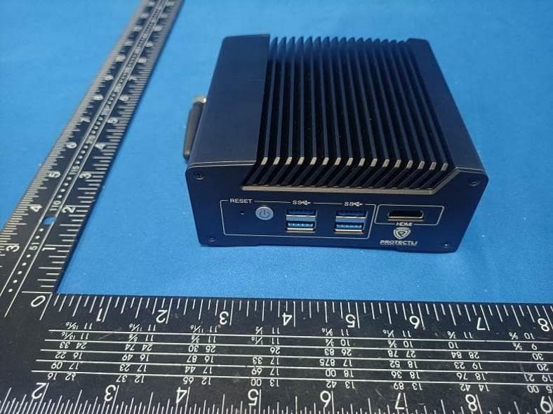
Click to zoom
Application Details
- Equipment Class
- DSS - Part 15 Spread Spectrum Transmitter
- Date of Grant
- Apr 16, 2024
- Application Purpose
- Original Equipment
- Date of Application
- Apr 16, 2024
- Equipment Note
- Mini PCs
- Frequency Range
- 2402.00000000 - 2480.00000000
- Country
- United States
Documents & Files
Document Text
Text extracted from the exhibit documents filed with the FCC. Open a document above to read the original.
Users Manual
User Manual For V1210 Mini PC V2024 1.0 This User Manual was designed for Protectli V12XX series Mini PCs. Including the typical model V1210 which is a 2 port networks hard ware. 1. Application The most important consideration for choosing your hardware is what application it will be used for. The Protectli Vault can be used in a number of different applications. Customers have deployed Vaults as Windows Clients, Linux Desktops and Servers, Hypervisors, and of course firewalls. Thinking about the requirements for your use case will help to narrow your choice when it comes to picking your Vault. Our recommendation: Simple client machines will work great on our smaller 2-port Vaults, while you may want to consider a 4-port or 6-port for firewall or hypervisor applications. 2. Ports The number of ethernet ports you need depends on your application. Firewalls can be configured on as little as a two physical ports, but for simplicity and throughput, consider that you may want multiple physical ports to segment traffic for multiple networks (i.e. a ‘secure’ network, an ‘IoT’ network, a ‘guest’ network, etc). For hypervisor applications, consider that a physical port can be ‘passed through’ to an individual virtual machine so multiple virtual machines may need more physical ports. The Vault is currently available in 2-Port, 4-Port, and 6-Port variations. In addition, some models have 2.5G or 10G Ethernet ports. Our recommendation: It is smart to think about future-proofing your Vault from the start, so consider a model with more Ethernet ports and 3. Throughput Requirements Every Vault’s Ethernet ports are PCIe connected to the CPU and can run at linerate of either 1 Gbps, 2.5 Gbps or 10 Gbps. FIREWALL As a firewall, every Vault has tested at full wire speed between ports using iperf as a synthetic load. As such, for basic routing applications any Vault is capable of gigabit throughput. However, in most firewall application, additional services will be turned on that consume CPU and thus may reduce throughput. These include modest services such as DHCP and DNS or heavy CPU users such as Deep Packet Inspection (DPI). A key consideration is Virtual Private Networking (VPN) support. VPN requires processor intensive encryption. Our recommendation: With a modest throughput of up to ~300 Mbps, you can run many firewall applications in ‘basic’ routing and firewall mode on any of our 2-Port or 4-Port port models. With increased throughput (especially gigabit service) or if implementing VPN, DPI, IPS/IDS, SNORT, Sensei, or other firewall add-ons, we recommend a Vault with a performant CPU such as the VP4600 or VP6600. Note: For sample VPN throughput tests we have performed to show baselined performance across all models, check out our OpenVPN and IPSEC VPN tests. HYPERVISOR For hypervisor applications, the Vault’s multiple gigabit ports are ideal for dedicated physical connections passed through to individual VM’s. Our recommendation: In most circumstances, using a Vault as a hypervisor means that the user will want to run multiple operating systems, requiring CPU, memory, and network connections. As such, we recommend the 6-Port Units . 4. Security Security is an important consideration for any network or compute appliance. coreboot is available as an open source BIOS on all the Vaults. In addition, the Vault Pro (VP) series have additional security features. Our recommendation: If security is important, we recommend coreboot in general and the advanced security features available on the Vault Pro Series. 5. Workload and Hardware Requirements by OS The OS you choose to run can greatly affect the performance requirements of the Vault. Some customers use the Vault to run a basic firewall, while others use it as a hypervisor, desktop, or SD-WAN. Therefore, hardware requirements vary widely. Here are a few examples of usage that typically require a stronger CPU. • Routing all network traffic through a VPN requires higher CPU clock speeds, especially at higher throughput. Click here for more performance results. • Running add-on packages like pfBlocker (pfSense), SNORT (pfSense), or Sensei (OPNsense) • Using the Vault to run a hypervisor, and/or having other software running on the same device. Here are hardware recommendations for common OS’s: 6. The V1210 Photo The Front Side The Back Side 7. The Specifications 8. The Steps For Users Step One: Plug the power adaptor Step Two: Connect any display with HDMI cable Step Three: Press the power-on button, color blue Step four: Install the OS you needed Step Five: Plug in the networks cable and make setting with OS
Users Manual
FCC Caution. § 15.19 Labelling requirements. This device complies with part 15 of the FCC Rules. Operation is subject to the following two conditions: (1) This device may not cause harmful interference, and (2) this device must accept any interference received, including interference that may cause undesired operation. § 15.21 Information to user. Any Changes or modifications not expressly approved by the party responsible for compliance could void the user's authority to operate the equipment. § 15.105 Information to the user. Note: This equipment has been tested and found to comply with the limits for a Class B digital device, pursuant to part 15 of the FCC Rules. These limits are designed to provide reasonable protection against harmful interference in a residential installation. This equipment generates uses and can radiate radio frequency energy and, if not installed and used in accordance with the instructions, may cause harmful interference to radio communications. However, there is no guarantee that interference will not occur in a particular installation. If this equipment does cause harmful interference to radio or television reception, which can be determined by turning the equipment off and on, the user is encouraged to try to correct the interference by one or more of the following measures: -Reorient or relocate the receiving antenna. -Increase the separation between the equipment and receiver. -Connect the equipment into an outlet on a circuit different from that to which the receiver is connected. -Consult the dealer or an experienced radio/TV technician for help. RF warning for Mobile device: This equipment complies with FCC radiation exposure limits set forth for an uncontrolled environment. This equipment should be installed and operated withminimum distan ce 20cm between the radiator & your body.
Attestation Statements
Dewolf Technologies, Inc (DBA Protectli) (2024/04/09) Eurofins Electrical and Electronic Testing NA, Inc. 914 West Patapsco Avenue Baltimore, MD 21230 RE: Attestation Statements Part 2.911(d)(5)(i) request for (2A23B-V12XX) [Dewolf Technologies, Inc (DBA Protectli)] (“the applicant”) certifies that the equipment for which authorization is sought is not “covered” equipment prohibited from receiving an equipment authorization pursuant to section 2.903 of the FCC rules. Sincerely, (Applicant signature) Brent Cowing Dewolf Technologies, Inc (DBA Protectli) (2024/04/09) Eurofins Electrical and Electronic Testing NA, Inc. 914 West Patapsco Avenue Baltimore, MD 21230 RE: Attestation Statements Part 2.911(d)(5)(ii) request for (2A23B-V12XX) [Dewolf Technologies, Inc (DBA Protectli)] (“the applicant”) certifies that, as of the date of the filing of the application, the applicant is not identified on the Covered List as an entity producing “covered” equipment. Sincerely, (Applicant signature) Brent Cowing
Attestation Statements
Attestation Statements (2024/04/09) TO: Federal Communications Commission Authorization and Evaluation Division 7435 Oakland Mills Road Columbia, MD 21046, USA RE: Attestation Statements Part 2.911(d)(7) request for (2A23B-V12XX) (Dewolf Technologies, Inc (DBA Protectli)), the undersigned, hereby authorize (Dewolf Technologies, Inc (DBA Protectli)) to act as our designated U.S. agent for service of process, (Dewolf Technologies, Inc (DBA Protectli)) accepts to maintain an agent for no less than one year after the grantee has terminated all marketing and importation or the conclusion of any Commission-related proceeding involving the equipment. (Dewolf Technologies, Inc (DBA Protectli)) accepts the responsibility to act as designated U.S. agent for service of process. Applicant Information: Company name: Dewolf Technologies, Inc (DBA Protectli) Contact Name: Brent Cowing Address: 1315 Hot Springs Way STE 107 Vista, CA 92081 Telephone No: 1-760-230-5899 Email: [email protected] Signature Brent Cowing U.S. Agent Information: Company Name: Dewolf Technologies, Inc (DBA Protectli) Address: Brent Cowing FRN: 0031329642 Contact Name: Brent Cowing Telephone No: 1-760-230-5899 Email: [email protected] Signature Brent Cowing
Cover Letter(s)
Dewolf Technologies, Inc (DBA Protectli) Model Difference Model: V1210, V1410, V1610, V1810 All the models are the same circuit and RF module, except the models names. Regards Sincerely, Client’s signature Client’s signature: Client’s name / title: Brent Cowing / Manager 1315 Hot Springs Way STE 107 Vista, CA 92081
Cover Letter(s)
Dewolf Technologies, Inc (DBA Protectli) 04/02/2024 Eurofins Electrical and Electronic Testing NA, Inc. 914 West Patapsco Avenue Baltimore, MD 21230 RE: CONFIDENTIALITY REQUEST FOR (Mini PCs / # AND FCC ID: 2A23B-V12XX To Whom It May Concern: This letter serves as an official request for confidentiality under sections 0.457 and 0.459 of CFR 47. We have requested that the - Block Diagram - Schematics - Operational Description required to be submitted with this application be permanently withheld from public review. The above documents are company proprietary information that could never get into the possession of your competition. Please contact me if there is any information you may need. Sincerely, Client’s signature: Client’s name / title: Brent Cowing / Manager 1315 Hot Springs Way STE 107 Vista, CA 92081
Cover Letter(s)
Dewolf Technologies, Inc (DBA Protectli) 04/02/2024 Eurofins Electrical and Electronic Testing NA, Inc. 914 West Patapsco Avenue Baltimore, MD 21230 RE: LETTER OF AGENT AUTHORIZATION To Whom It May Concern: We, the undersigned, hereby authorize (Shenzhen CTA Testing Technology Co., Ltd.) to act on our behalf in all matters relating to application for equipment authorization, including the signing of all documents relating to these matters. We also hereby certify that no party to the application authorized hereunder is subject to the denial of benefits, including FCC benefits, pursuant to Section 5301 of the Anti-Drug Abuse Act of 1988, 21 U.S.C.853(a). This agreement expires one year from the current date. Sincerely, Client’s signature: Client’s name / title: Brent Cowing / Manager 1315 Hot Springs Way STE 107 Vista, CA 92081
External Photos
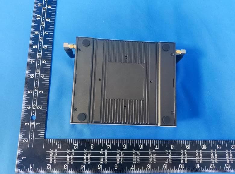
FCC ID: 2A23B-V12XX External Photos of the EUT FCC ID: 2A23B-V12XX BT/2.4G WIFI External Antenna 1 2.4G WIFI External Antenna 2 FCC ID: 2A23B-V12XX
ID Label/Location Info
2.2*4.1cm
Internal Photos
FCC ID: 2A23B-V12XX Internal Photos of the EUT FCC ID: 2A23B-V12XX FCC ID: 2A23B-V12XX FCC ID: 2A23B-V12XX FCC ID: 2A23B-V12XX
RF Exposure Info
RF Exposure evaluation FCC ID: 2A23B-V12XX Exposure category: General population/uncontrolled environment EUT Type: Production Unit Device Type: Mobile Device 1. Reference According to §1.1307(b)(1), systems operating under the provisions of this section shall be operated in a manner that ensures that the public is not exposed to radio frequency energy level in excess of the Commission’s guidelines. According to §1.1310 and §2.1091 RF exposure is calculated. KDB447498 D01: Mobile and Portable Devices RF Exposure Procedures and Equipment Authorization Policies 2. Limit Limits for Maximum Permissible Exposure (MPE)/Controlled Exposure Frequency Range(MHz) Electric Field Strength(V/m) Magnetic Field Strength(A/m) Power Density (mW/cm²) Averaging Time (minute) Limits for Occupational/Controlled Exposure 0.3 – 3.0 3.0 – 30 30 – 300 300 – 1500 1500 – 100,000 614 1842/f 61.4 / / 1.63 4.89/f 0.163 / / (100) * (900/f 2 )* 1.0 f/300 5 6 6 6 6 6 Limits for Maximum Permissible Exposure (MPE)/Uncontrolled Exposure Frequency Range(MHz) Electric Field Strength(V/m) Magnetic Field Strength(A/m) Power Density (mW/cm²) Averaging Time (minute) Limits for Occupational/Controlled Exposure 0.3 – 3.0 3.0 – 30 30 – 300 300 – 1500 1500 – 100,000 614 824/f 27.5 / / 1.63 2.19/f 0.073 / / (100) * (180/f 2 )* 0.2 f/1500 1.0 30 30 30 30 30 F=frequency in MHz *=Plane-wave equivalent power density 3. MPE Calculation Method Predication of MPE limit at a given distance Equation from page 18 of OET Bulletin 65, Edition 97-01 S=PG/4πR² Where: S=power density P=power input to antenna G=power gain of the antenna in the direction of interest relative to an isotropic radiator R=distance to the center of radiation of the antenna 4. Antenna Information Briller can only use antennas certificated as follows provided by manufacturer; Antenna No. Model No. of antenna: Type of antenna: Gain of the antenna (Max.) Frequency range: 2.4GWIFI antenna1/2 / External ANT 2.00dBi for 2400-2500MHz 2.4GBT antenna / External ANT 2.00dBi for 2400-2500MHz 2.4GBLE antenna / External ANT 2.00dBi for 2400-2500MHz 5. Manufacturing Tolerance Antenna1: IEEE 802.11b (Average) Frequency (MHz) 2412 2437 2462 Target (dBm) 15.0 15.0 15.0 Tolerance ± (dB) 1.0 1.0 1.0 IEEE 802.11g (Average) Frequency (MHz) 2412 2437 2462 Target (dBm) 15.0 15.0 15.0 Tolerance ± (dB) 1.0 1.0 1.0 IEEE 802.11n HT20 (Average) Frequency (MHz) 2412 2437 2462 Target (dBm) 15.0 15.0 15.0 Tolerance ± (dB) 1.0 1.0 1.0 Antenna2: IEEE 802.11b (Average) Frequency (MHz) 2412 2437 2462 Target (dBm) 15.0 15.0 15.0 Tolerance ± (dB) 1.0 1.0 1.0 IEEE 802.11g (Average) Frequency (MHz) 2412 2437 2462 Target (dBm) 15.0 15.0 15.0 Tolerance ± (dB) 1.0 1.0 1.0 IEEE 802.11n HT20 (Average) Frequency (MHz) 2412 2437 2462 Target (dBm) 15.0 15.0 15.0 Tolerance ± (dB) 1.0 1.0 1.0 BT 1Mbps Frequency (MHz) 2402 2440 2480 Target (dBm) 0 0 0 Tolerance ± (dB) 1.0 1.0 1.0 BT 2Mbps Frequency (MHz) 2402 2440 2480 Target (dBm) -1 -1 -1 Tolerance ± (dB) 1.0 1.0 1.0 BT 3Mbps Frequency (MHz) 2402 2440 2480 Target (dBm) -1 -1 -1 Tolerance ± (dB) 1.0 1.0 1.0 BLE Frequency (MHz) 2402 2440 2480 Target (dBm) 2.0 2.0 2.0 Tolerance ± (dB) 1.0 1.0 1.0 6. Standalone MPE Result As declared by the Applicant, the EUT is a wireless device used in a fix application, at least 20 cm from any body part of the user or nearby persons; from the maximum EUT RF output power, the minimum separation distance, r =20cm, as well as the gain of the used antenna is 2.0dBi, the RF power density can be obtained. Modulation Type Output power Antenna Gain (dBi) Antenna Gain (linear) MPE (mW/cm 2 ) MPE Limits (mW/cm 2 ) dBm mW 2.4GWIFI ANT1 16.0 39.81 2.0 1.58 0.0125 1.0000 2.4GWIFI ANT2 16.0 39.81 2.0 1.58 0.0125 1.0000 BT ANT 1 1.26 2.0 1.58 0.0004 1.0000 BLE ANT 3 2.00 2.0 1.58 0.0006 1.0000 Remark: 1. Output power (Peak) including turn-up tolerance; 2. MPE evaluate distance is 20cm from user manual provide by manufacturer. 7. simultaneous MPE Result 2.4G WIFI ANT1 MPE (Ratio) 2.4G WIFI ANT2 MPE (Ratio)) simultaneous MPE (Ratio) MPE Limits 0.0125 0.0125 0.025 1 8. Conclusion The measurement results comply with the FCC Limit per 47 CFR 2.1091 for the uncontrolled RF Exposure of mobile device. ----------------THE END OF REPORT---------------
Test Report
1. Antenna Description: Antenna type External antenna Model V1210 Frequency range 2400-2500MHz Manufacturer Shenzhen Gowin Solution Co.,Ltd. ANT Peak Gain 2.00 dBi 2. Antenna Photo: 3. Test Equipment & Conditions 3.1 Test instrument VSWR is tested using Agilent E5071B connected to a hand mechanism, and the status is free space. 3.2 Test environment and methods 4.Antenna Radiation Pattern 2400MHz 2450MHz 2500MHz
Test Report
Shenzhen CTA Testing Technology Co., Ltd. Room 106, Building 1, Yibaolai Industrial Park, Qiaotou Community, Fuhai Street, Bao’an District, Shenzhen, China Shenzhen CTA Testing Technology Co., Ltd. Room 106, Building 1, Yibaolai Industrial Park, Qiaotou Community, Fuhai Street, Bao’an District, Shenzhen, China Tel:+86-755 2322 5875 E-mail:[email protected] Web:http://www.cta-test.cn FCC PART 15 SUBPART C TEST REPORT FCC PART 15.247 Report Reference No. ..................... : FCC ID............................................. : CTA24032501902 2A23B-V12XX Compiled by ( position+printed name+signature) . : File administrators Zoey Cao Supervised by ( position+printed name+signature) . : Project Engineer Amy Wen Approved by ( position+printed name+signature) . : RF Manager Eric Wang Date of issue .................................... : Apr. 01, 2024 Testing Laboratory Name .............. : Shenzhen CTA Testing Technology Co., Ltd. Address ............................................ : Room 106, Building 1, Yibaolai Industrial Park, Qiaotou Community, Fuhai Street, Bao‘an District, Shenzhen, China Applicant’s name ............................ : Dewolf Technologies, Inc (DBA Protectli) Address ............................................ : 1315 Hot Springs Way STE 107 Vista, CA 92081 Test specification ........................... : Standard ........................................... : FCC Part 15.247 Shenzhen CTA Testing Technology Co., Ltd. All rights reserved. This publication may be reproduced in whole or in part for non-commercial purposes as long as the Shenzhen CTA Testing Technology Co., Ltd. is acknowledged as copyright owner and source of the material. Shenzhen CTA Testing Technology Co., Ltd. takes no responsibility for and will not assume liability for damages resulting from the reader's interpretation of the reproduced material due to its placement and context. Test item description ..................... : Mini PCs Trade Mark ....................................... : N/A Manufacturer .................................... : Shenzhen Gowin Solution Co.,Ltd. Model/Type reference ...................... : V1210 Listed Models .................................. : V1410, V1610, V1810 Modulation ....................................... : GFSK, Π/4DQPSK, 8DPSK Frequency ......................................... From 2402MHz to 2480MHz Rating ............................................... : DC 12.0V From external circuit Result ............................................... : PASS Report No.: CTA24032501902 Page 2 of 45 Shenzhen CTA Testing Technology Co., Ltd. Room 106, Building 1, Yibaolai Industrial Park, Qiaotou Community, Fuhai Street, Bao’an District, Shenzhen, China Tel:+86-755 2322 5875 E-mail:[email protected] Web:http://www.cta-test.cn T E S T R E P O R T Equipment under Test : Mini PCs Model /Type : V1210 Listed Models : V1410, V1610, V1810 Applicant : Dewolf Technologies, Inc (DBA Protectli) Address : 1315 Hot Springs Way STE 107 Vista, CA 92081 Manufacturer : Shenzhen Gowin Solution Co.,Ltd. Address : RM212-213, Building C, Liuwei Business Center, Bantian Street, Longgang District, Shenzhen, China 518000 Test Result: PASS The test report merely corresponds to the test sample. It is not permitted to copy extracts of these test result without the written permission of the test laboratory. Report No.: CTA24032501902 Page 3 of 45 Shenzhen CTA Testing Technology Co., Ltd. Room 106, Building 1, Yibaolai Industrial Park, Qiaotou Community, Fuhai Street, Bao’an District, Shenzhen, China Tel:+86-755 2322 5875 E-mail:[email protected] Web:http://www.cta-test.cn Contents 1 T E S T S T A N D A R D S .................................................................. 4 2 S U M M A R Y ............................................................................. 5 2.1 General Remarks 5 2.2 Product Description 5 2.3 Equipment Under Test 5 2.4 Short description of the Equipment under Test (EUT) 5 2.5 EUT operation mode 6 2.6 Block Diagram of Test Setup 6 2.7 Related Submittal(s) / Grant (s) 6 2.8 Modifications 6 3 T E S T E N V I R O N M E N T ............................................................... 7 3.1 Address of the test laboratory 7 3.2 Test Facility 7 3.3 Environmental conditions 7 3.4 Summary of measurement results 8 3.5 Statement of the measurement uncertainty 8 3.6 Equipments Used during the Test 9 4 T E S T C O N D I T I O N S A N D R E S U L T S ............................................ 11 4.1 AC Power Conducted Emission 11 4.2 Radiated Emission 14 4.3 Maximum Peak Output Power 20 4.4 20dB Bandwidth 21 4.5 Frequency Separation 25 4.6 Number of hopping frequency 27 4.7 Time of Occupancy (Dwell Time) 29 4.8 Out-of-band Emissions 33 4.9 Pseudorandom Frequency Hopping Sequence 42 4.10 Antenna Requirement 43 5 T E S T S E T U P P H O T O S O F T H E E U T .......................................... 44 6 P H O T O S O F T H E EUT ............................................................. 45 Report No.: CTA24032501902 Page 4 of 45 Shenzhen CTA Testing Technology Co., Ltd. Room 106, Building 1, Yibaolai Industrial Park, Qiaotou Community, Fuhai Street, Bao’an District, Shenzhen, China Tel:+86-755 2322 5875 E-mail:[email protected] Web:http://www.cta-test.cn 1 T E S T S T A N D A R D S The tests were performed according to following standards: FCC Rules Part 15.247: Frequency Hopping, Direct Spread Spectrum and Hybrid Systems that are in operation within the bands of 902-928 MHz, 2400-2483.5 MHz, and 5725-5850 MHz. ANSI C63.10-2013: American National Standard for Testing Unlicensed Wireless Devices Report No.: CTA24032501902 Page 5 of 45 Shenzhen CTA Testing Technology Co., Ltd. Room 106, Building 1, Yibaolai Industrial Park, Qiaotou Community, Fuhai Street, Bao’an District, Shenzhen, China Tel:+86-755 2322 5875 E-mail:[email protected] Web:http://www.cta-test.cn 2 S U M M A R Y 2.1 General Remarks Date of receipt of test sample : Mar. 22, 2024 Testing commenced on : Mar. 22, 2024 Testing c…
Text truncated - open the document above for the full version.
Test Report
Report No.: CTA24032501902 Page 33 of 45 Shenzhen CTA Testing Technology Co., Ltd. Room 106, Building 1, Yibaolai Industrial Park, Qiaotou Community, Fuhai Street, Bao’an District, Shenzhen, China Tel:+86-755 2322 5875 E-mail:[email protected] Web:http://www.cta-test.cn 4.8 Out-of-band Emissions Limit In any 100 kHz bandwidth outside the frequency band in which the spread spectrum or digitally modulated intentional radiator is operating, the radio frequency power that is produced by the intentional radiator shall be at least 20 dB below that in the 100 kHz bandwidth within the band that contains the highest level of the desired power, based on either an RF con-ducted or a radiated measurement, pro-vided the transmitter demonstrates compliance with the peak conducted power limits. If the transmitter com-plies with the conducted power limits based on the use of RMS averaging over a time interval, as permitted under paragraph (b)(3) of this section, the attenuation required under this paragraph shall be 30 dB instead of 20 dB. Attenuation below the general limits specified in §15.209(a) is not required. Test Procedure Connect the transmitter output to spectrum analyzer using a low loss RF cable, and set the spectrum analyzer to RBW=100 kHz, VBW= 300 kHz, peak detector , and max hold. Measurements utilizing these setting are made of the in-band reference level, bandedge and out-of-band emissions. Test Configuration EUT SPECTRUM ANALYZER Test Results Remark: The measurement frequency range is from 30MHz to the 10th harmonic of the fundamental frequency. The lowest, middle and highest channels are tested to verify the spurious emissions and bandage measurement data. We measured all conditions (DH1, DH3, DH5) and recorded worst case at DH5 Test plot as follows: Report No.: CTA24032501902 Page 34 of 45 Shenzhen CTA Testing Technology Co., Ltd. Room 106, Building 1, Yibaolai Industrial Park, Qiaotou Community, Fuhai Street, Bao’an District, Shenzhen, China Tel:+86-755 2322 5875 E-mail:[email protected] Web:http://www.cta-test.cn GFSK(CH00) GFSK(CH39) reference reference 30MHz-1G 30MHz-1G 1G-25G 1G-25G Report No.: CTA24032501902 Page 35 of 45 Shenzhen CTA Testing Technology Co., Ltd. Room 106, Building 1, Yibaolai Industrial Park, Qiaotou Community, Fuhai Street, Bao’an District, Shenzhen, China Tel:+86-755 2322 5875 E-mail:[email protected] Web:http://www.cta-test.cn GFSK(CH78) π/4DQPSK (CH00) reference reference 30MHz-1G 30MHz-1G 1G-25G 1G-25G Report No.: CTA24032501902 Page 36 of 45 Shenzhen CTA Testing Technology Co., Ltd. Room 106, Building 1, Yibaolai Industrial Park, Qiaotou Community, Fuhai Street, Bao’an District, Shenzhen, China Tel:+86-755 2322 5875 E-mail:[email protected] Web:http://www.cta-test.cn π/4DQPSK (CH39) π/4DQPSK (CH78) reference reference 30MHz-1G 30MHz-1G 1G-25G 1G-25G Report No.: CTA24032501902 Page 37 of 45 Shenzhen CTA Testing Technology Co., Ltd. Room 106, Building 1, Yibaolai Industrial Park, Qiaotou Community, Fuhai Street, Bao’an District, Shenzhen, China Tel:+86-755 2322 5875 E-mail:[email protected] Web:http://www.cta-test.cn 8DPSK (CH00) 8DPSK (CH39) reference reference 30MHz-1G 30MHz-1G 1G-25G 1G-25G Report No.: CTA24032501902 Page 38 of 45 Shenzhen CTA Testing Technology Co., Ltd. Room 106, Building 1, Yibaolai Industrial Park, Qiaotou Community, Fuhai Street, Bao’an District, Shenzhen, China Tel:+86-755 2322 5875 E-mail:[email protected] Web:http://www.cta-test.cn 8DPSK (CH78) reference 30MHz-1G 3G-25G Report No.: CTA24032501902 Page 39 of 45 Shenzhen CTA Testing Technology Co., Ltd. Room 106, Building 1, Yibaolai Industrial Park, Qiaotou Community, Fuhai Street, Bao’an District, Shenzhen, China Tel:+86-755 2322 5875 E-mail:[email protected] Web:http://www.cta-test.cn Band-edge Measurements for RF Conducted Emissions: GFSK Left Band edge hoping off Right Band edge hoping off Left Band edge hoping on Right Band edge hoping on Report No.: CTA24032501902 Page 40 of 45 Shenzhen CTA Testing Technology Co., Ltd. Room 106, Building 1, Yibaolai Industrial Park, Qiaotou Community, Fuhai Street, Bao’an District, Shenzhen, China Tel:+86-755 2322 5875 E-mail:[email protected] Web:http://www.cta-test.cn π/4DQPSK Left Band edge hoping off Right Band edge hoping off Left Band edge hoping on Right Band edge hoping on Report No.: CTA24032501902 Page 41 of 45 Shenzhen CTA Testing Technology Co., Ltd. Room 106, Building 1, Yibaolai Industrial Park, Qiaotou Community, Fuhai Street, Bao’an District, Shenzhen, China Tel:+86-755 2322 5875 E-mail:[email protected] Web:http://www.cta-test.cn 8DPSK Left Band edge hoping off Right Band edge hoping off Left Band edge hoping on Right Band edge hoping on Report No.: CTA24032501902 Page 42 of 45 Shenzhen CTA Testing Technology Co., Ltd. Room 106, Building 1, Yibaolai Industrial Park, Qiaotou Community, Fuhai Street, Bao’an District, Shenzhen, China Tel:+86-755 2322 5875 E-mail:[email protected] Web:http://www.cta-test.cn 4.9 Pseudorandom Frequency Hopping Sequence TEST APPLICABLE For 47 CFR Part 15C section 15.247 (a) (1) requirement: Frequency hopping systems shall have hopping channel carrier frequencies separated by a minimum of 25 kHz or the 20 dB bandwidth of the hop-ping channel, whichever is greater. Alternatively, frequency hopping systems operating in the 2400–2483.5 MHz band may have hopping channel carrier frequencies that are separated by 25 kHz or two-thirds of the 20 dB bandwidth of the hopping channel, whichever is greater, provided the systems operate with an output power no greater than 125 mW. The system shall hop to channel frequencies that are selected at the system hopping rate from a pseudo randomly ordered list of hopping frequencies. Each frequency must be used equally on the average by each transmitter. The system receivers shall have input bandwidths that match the hop-ping channel bandwidths of their corresponding transmitters and shall shift frequencies in synchronization with the transmitted signals. EUT Pseudorandom Frequency Hopp…
Text truncated - open the document above for the full version.
Contact Information
Applicant
Brent Cowing
Technical Contact
Shenzhen CTA Testing Technology Co., Ltd.Eric Wang
[email protected]+8675523225875
Room 106, Building 1, Yibaolai Ind. Park · Shenzhen · China
Test Firm
SHENZHEN CTA TESTING TECHNOLOGY CO., LTD.Eric Wang
[email protected]+86 755 2322 5875
Technical Specifications
| # | Rule Parts | Frequency Range | Power Output |
|---|---|---|---|
| 1 | 15C | 2.40 GHz - 2.48 GHz | 920.00 µW |
Other Applications from Dewolf Technologies, Inc (DBA Protectli)
2A23B-V16XX
Aug 21, 2024Mini PCs
Equipment Class
DTS - Digital Transmission System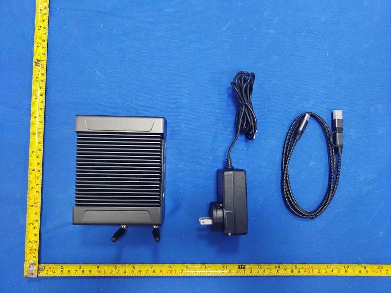
2A23B-V14XX
Jun 24, 2024Mini PCs
Equipment Class
DTS - Digital Transmission System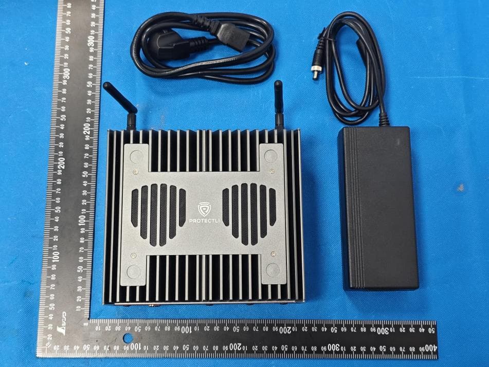
2A23B-VP6XXX
Feb 19, 2024Mini Pc
Equipment Class
DTS - Digital Transmission System