2A2T4-H502Smart Security Kit
Shenzhen XingAniot Technology Co., Ltd.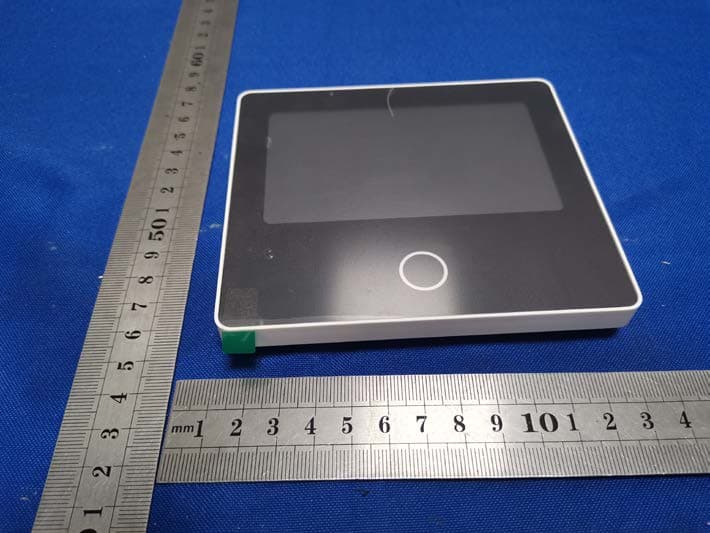
Click to zoom
Application Details
- Equipment Class
- DSC - Part 15 Security/Remote Control Transmitter
- Date of Grant
- Oct 05, 2022
- Application Purpose
- Original Equipment
- Date of Application
- Oct 05, 2022
- Equipment Note
- Smart Security Kit
- Frequency Range
- 433.92000000 - 433.92000000
- Country
- China
Documents & Files
Document Text
Text extracted from the exhibit documents filed with the FCC. Open a document above to read the original.
Users Manual
Smart Security Panel Kit User Manual CONTENT I.General Description................................................................................................................................. 1 1.1 Product Example ...................................................................................................................... 1 1.2 Home Installation Diagram........................................................................................................ 2 II.Set up the Security Devices .................................................................................................................... 3 2.1 Security Panel ............................................................................................................................ 3 2.2 Entry Sensor ............................................................................................................................... 6 2.3 Motion Sensor ............................................................................................................................ 8 2.4 Controller .................................................................................................................................... 9 2.5 Multifunction Button---Doorbell/SOS Button .......................................................................... 10 III.Learn to Use the Security Panel ........................................................................................................... 11 3.1 Main Interface .......................................................................................................................... 11 3.2 Menu introduction .................................................................................................................... 12 IV.Troubleshooting and Maintenance ............................................................................................. 14 V.Hazardous Substance Declaration ....................................................................................................... 15 VI.Warranty Rules ............................................................................................................................. 15 VII.FCC declares ................................................................................................................................ 16 1 / 16 I.General Description 1.1 Product Example Security Panel The central hub of the security system. Using 4.3-inch IPS capacitive touch screen, built-in high- performance low-power intelligent microprocessor. With a variety of installation methods: wall- mounted, desktop placement. Added built-in siren, up to 110dB. It connects all of your accessories to the APP, so you can stay in control of your home from anywhere. Accessories list: (Subject to actual packaging) Multifunction Button Entry Sensor Controller Motion Sensor Send the alarm signal to the panel when the door or window are opened, it is recommended to install at important entrances. Doorbell button or SOS button After pairing with the security panel, quickly "Away", "Home", and "Disarm" the security system, and trigger the emergency alarm. Send the alarm signal to the panel when the movement is detected. 2 / 16 1.2 Home Installation Diagram Motion Sensor Doorbell Button Controller Security Panel Entry Sensor SOS Button 3 / 16 II.Set up the Security Devices 2.1 Security Panel Installation Diagram (1)Wall Mount (2)Placed on the Desktop Security Panel×1 Wall Hanging Plate×1 Screws×2 1. Install the hanging plate on the wall with screws. Note: The screws must be all nailed to the wall, and the hanging board must be parallel. F 2. Align the hole on the back of the panel with the hanging plate and install it. Note: For concealed wire installation, please remove the bracket and cable clip. Note: 1)Installed in the center of the home to facilitate signal reception and transmission. 2)Avoid installing all devices on metal surfaces, as well as on load-bearing walls. Comes with a Stand on the Back It can be directly placed on the desktop, free from the installation of holes on the wall, and can be placed anywhere in the home. 4 / 16 Appearance Design Front View Rear Main View Indicator: 5 / 16 Alarm Modes A.Security Panel Alarm Modes a.Away: The security panel is in a monitoring state, when the accessories are triggered, the security panel will alarm. b.Home: When the user is at home, in this mode, some areas can be monitored and alarms. c.Disarm: The security panel cancels the monitoring state, and only the SOS button or the accessories set to "Always" mode can trigger the alarm. B.Accessories Modes: a.Away/Home: When the security panel is in the "Away" or "Home" state, the panel will alarm after the sensor is triggered. It is recommended that the outdoor sensor can be set to this mode. b.Away: When the security panel is in the "Away" state, the panel will alarm after the sensor is triggered. It is recommended that the outdoor detector can be set to this mode. c.Always: Regardless of the state of the security panel, any time the sensor is triggered, the panel will alarm. It is recommended to set this mode for gas leaks or smoke detectors, etc. d.Disabled: The security panel will not respond to the alarm request of the sensor set in this mode. Note: You can choose which sensors are armed in Home and Away mode, or both, or always active. For example, if you want to avoid triggering the alarm when you are at home, you can set the specific sensor in Away mode. Then when you set the panel in “Home” state, the alarm will not be triggered, only in “Away” state, the alarm will be triggered. 6 / 16 2.2 Entry Sensor Configure On the Security Panel: A. Go to Menu---Accessories---Enter User Code (Default: 1234). B. Press Sensor---“+” ----Entry, then set the Mode, Delay, and Advanced settings. C. Press “+ Pair”, then trigger the Entry sensor (Just separate the two parts). D. Paired successfully, rename the sensors on the APP. Installation The entry se…
Text truncated - open the document above for the full version.
Attestation Statements
Shenzhen XingAniot Technology Co., Ltd. Model Difference Data:2022.09.23 Product description: Smart Security Kit Model name: H502, H700 Trade Name: N/A FCC ID: 2A2T4-H502 All the model are the same circuit and RF module, except model names . Regards Sincerely Client’s signature : Client’s name / title : Zhao Ping(Manager) Contact information / address:1508, towerB, 1003, Nanxin Road, Shenzhen, China 51800
Cover Letter(s)
Shenzhen XingAniot Technology Co., Ltd. (2022.09.23) Eurofins Electrical and Electronic Testing NA, Inc. 914 West Patapsco Avenue Baltimore, MD 21230 RE: CONFIDENTIALITY REQUEST FOR (Smart Security Kit / H502, H700/ FCC ID: 2A2T4-H502) To Whom It May Concern: This letter serves as an official request for confidentiality under sections 0.457 and 0.459 of CFR 47. We have requested that the Exhibits Long-Term Confidentiality Short-Term Confidentiality NOTE 2 ID Label/Location No No Attestation Statement No No External Photos No ☐ Block Diagram ☒ ☐ Schematics ☒ ☐ Test Report No No Test Setup Photos No ☐ User’s Manual ☐ NOTE 1 ☐ Internal Photos ☐ NOTE 1 ☐ Parts List / Tune Up ☐ ☐ RF Exposure Info No No Operational Description ☒ ☐ Cover Letter(s) No No SDR Software / Security Info ☐ No required to be submitted with this application be permanently withheld from public review. Above mentioned document contains detailed system and equipment description are considered as proprietary information in operation of the equipment. The public disclosure of above documents might be harmful to our company and would give competitor an unfair advantage in the market. Please contact me if there is any information you may need. Sincerely, Signature: Name: Zhao Ping Title: Manager
Cover Letter(s)
Shenzhen XingAniot Technology Co., Ltd. (2022.09.23) Eurofins Electrical and Electronic Testing NA, Inc. 914 West Patapsco Avenue Baltimore, MD 21230 RE: LETTER OF AGENT AUTHORIZATION To Whom It May Concern: We, the undersigned, hereby authorize (Shenzhen CTB Testing Technology Co., Ltd.) to act on our behalf in all matters relating to application for equipment authorization, including the signing of all documents relating to these matters. We also hereby certify that no party to the application authorized hereunder is subject to the denial of benefits, including FCC benefits, pursuant to Section 5301 of the Anti-Drug Abuse Act of 1988, 21 U.S.C.853(a). This agreement expires one year from the current date. Sincerely, Signature: Name: Zhao Ping Title: Manager
External Photos
External Photos
ID Label/Location Info
Model: H502 FCC ID: 2A2T4-H502 Label Location
Internal Photos
Internal Photos 433 TX ANT 433 RX ANT
Parts List/Tune Up Info
APPlication(型号)TT02-2 ※Bluetooth Home RF(433天线) ※ISM band 2.4GHz (频率 433MHz) Applications(参数) Dimension(尺寸)
Test Report
Shenzhen CTB Testing Technology Co., Ltd. Report No.: CTB220922039RFX Report Tel: 4008-707-283 Web: http://www.ctb-lab.net Page 1 of 28 TEST REPORT Compiled by: Reviewed by: Approved by: Chen Zheng Arron Liu Bin Mei / Director The test report is effective only with both signature and specialized stamp. This result(s) shown in this report r Note: If there is any objection to the inspection results in this report, please submit a written report to the company within 15 days from the date of receiving the report. The test report is effective only with both signature and specialized stamp. This result(s) shown in this report refer only to the sample(s) tested. Without written approval of Shenzhen CTB Testing Technology Co., Ltd. this report can’t be reproduced except in full. The tested sample(s) and the sample information are provided by the client. “*” indicates the testing items were fulfilled by subcontracted lab. “#” indicates the items are not in CNAS accreditation scope. Product Name: Smart Security Kit FCC ID: 2A2T4-H502 Trademark: N/A Model Number: H502, H700 Prepared For: Shenzhen XingAniot Technology Co., Ltd. Address: 1508, towerB, 1003, Nanxin Road, Shenzhen, China 51800 Manufacturer: Shenzhen XingAniot Technology Co., Ltd. Address: 1508, towerB, 1003, Nanxin Road, Shenzhen, China 51800 Prepared By: Shenzhen CTB Testing Technology Co., Ltd. Address: Floor 1&2, Building A, No. 26 of Xinhe Road, Xinqiao Community, Xinqiao Street, Baoan District, Shenzhen, Guangdong, China. Sample Received Date: Sep. 14, 2022 Sample tested Date: Sep. 14, 2022 to Sep. 22, 2022 Issue Date: Sep. 22, 2022 Report No.: CTB220922039RFX Test Standards FCC Part15.231 ANSI C63.10:2013 Test Results PASS Remark: This is 433MHz radio test report. Shenzhen CTB Testing Technology Co., Ltd. Report No.: CTB220922039RFX Report Tel: 4008-707-283 Web: http://www.ctb-lab.net Page 2 of 28 TABLE OF CONTENT Test Report Declaration Page 1. VERSION ........................................................................................................................................ 3 2. TEST SUMMARY ........................................................................................................................... 4 3. MEASUREMENT UNCERTAINTY ................................................................................................. 5 4. PRODUCT INFORMATION AND TEST SETUP ............................................................................ 6 4.1 Product Information .......................................................................................................................... 6 4.2 Test Setup Configuration .................................................................................................................. 6 4.3 Support Equipment........................................................................................................................... 6 4.4 Test Mode ........................................................................................................................................ 7 4.5 Test Environment ............................................................................................................................. 7 5. TEST FACILITY AND TEST INSTRUMENT USED ....................................................................... 8 5.1 Test Facility ...................................................................................................................................... 8 5.2 Test Instrument Used ....................................................................................................................... 8 6. AC POWER LINE CONDUCTED EMISSION .................................................................................. 11 6.1 Block Diagram Of Test Setup ......................................................................................................... 11 6.2 Limit ................................................................................................................................................ 11 6.3 Test procedure ............................................................................................................................... 11 6.4 Test Result ..................................................................................................................................... 12 7. RADIATED EMISSION ................................................................................................................. 13 7.1 Block Diagram Of Test Setup ......................................................................................................... 13 7.2 Limit ................................................................................................................................................ 13 7.3 Test procedure ............................................................................................................................... 14 7.4 Test Result ..................................................................................................................................... 16 8. DWELL TIME ................................................................................................................................ 22 8.1 Block Diagram Of Test Setup ......................................................................................................... 22 8.2 Limit ................................................................................................................................................ 22 8.3 Test procedure ............................................................................................................................... 22 8.4 Test Result ..................................................................................................................................... 23 9. OCCUPIED BANDWIDTH ............................................................................................................ 24 9.1 Block Diagram Of …
Text truncated - open the document above for the full version.
Test Setup Photos
Radiated Emission Below 1G Above 1GHz
Contact Information
Applicant
Zhao Ping(Manager)
Technical Contact
Shenzhen XingAniot Technology Co., Ltd.Zhao Ping
[email protected]13692280695
1508, towerB, 1003, Nanxin Road, · Shenzhen, · China
Test Firm
Shenzhen CTB Testing Technology Co., Ltd.Rita Xiao
[email protected]86-13538218145
Technical Specifications
| # | Rule Parts | Frequency Range | Power Output |
|---|---|---|---|
| 1 | 15.231 | 433.92 MHz - 433.92 MHz | - |
Other Applications from Shenzhen XingAniot Technology Co., Ltd.
2A2T4-H320
Jul 31, 2023SecCube 3
Equipment Class
DSC - Part 15 Security/Remote Control Transmitter