2A2UNSR8C008-CHANNEL RECEIVER
ShenZhen FLYSKY Technology Co.,Ltd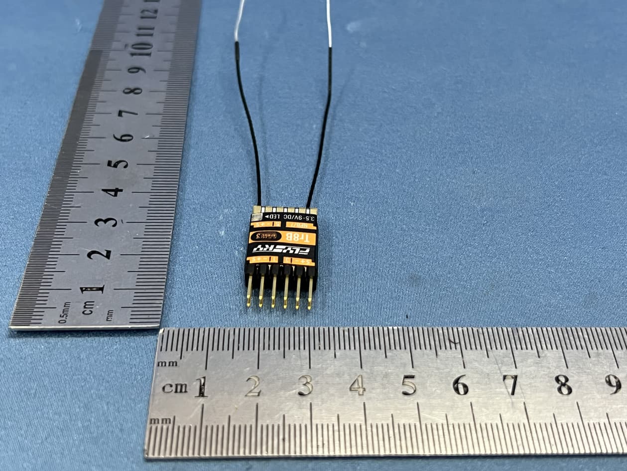
Click to zoom
Application Details
- Equipment Class
- DSS - Part 15 Spread Spectrum Transmitter
- Date of Grant
- Apr 28, 2022
- Application Purpose
- Original Equipment
- Date of Application
- Apr 28, 2022
- Equipment Note
- 8-CHANNEL RECEIVER
- Frequency Range
- 2406.00000000 - 2472.00000000
- Country
- China
Documents & Files
Document Text
Text extracted from the exhibit documents filed with the FCC. Open a document above to read the original.
Users Manual
FS-SR8C 接收机 Receiver http://www.flysky-cn.com Copyright ©2022 Flysky Technology co., ltd 产品型号:FS-SR8C 适配发射机:ANT 协议发射机(如 FS-ST8) 适合机种:固定翼、三角翼、滑翔机或机器人等 通道个数:8 无线频率:2.4GHz ISM 发射功率:小于 20dBm 无线标准:ANT 通道分辨率:4096 级 天线类型:双天线 (ipex4) 遥控距离:> 800 米 ( 空旷无干扰空中距离 ) 输入电源:3.5~9V/DC 工作电流:70mA/5V 输出数据:PWM/PPM/i-BUS/S.BUS 在线更新:支持 温度范围:-10°C ~ +60°C 湿度范围:20% ~ 95% 外形尺寸:22*15*3mm(不含插针和天线) 机身重量:1g(不含插针和天线) 2g(含 4*3Pin 插针和双天线) 认证:CE,FCC ID: 2A2UNSR8C00 FS-SR8C 是一款采用 ANT 协议支持 8 个 PWM 通道信号输出 的微型接收机。它具有扣式双天线,支持双向传输和回传功 能,设计小巧,可适配多种模型使用。本款接收机还提供了 DIY 配件,以满足不同的需求。 产品介绍 Introduction 接收机概览 Overview 产品规格 Specifications [1] CH1 通道接口 /PPM [2] CH3 通道接口 [3] 天线 [4] CH7 通道接口 [5] CH5 通道接口 [6] LED 灯 [7] CH6 通道接口 [8] CH8 通道接口 [9] BVD 线焊点 [10]SENS 信号端焊点 [11] SERVO/S.BUS 信号端焊点 [12] CH2 通道接口 [13] CH4 通道接口 [14] S( 信号端) [15] +( 电源正极 ) [1] CH1/PPM [2] CH3 [3] Antennas [4] CH7 [5] CH5 [6] LED [7] CH6 [8] CH8 [9] BVD cable welding point [10] SENS signal welding joint [11] SERVO signal welding joint [12]CH2 [13] CH4[14] Signal pin [15] + (Power anode) [16] - (Power cathode) Product Name: FS-SR8C Compatible Transmitters: Adapts transmitters with ANT protocol, such as FS-ST8 Compatible Models: Fixed-wing aircraft, delta-wing airplanes, gliders, or robots Numbers of Channel: 8 RF: 2.4GHz ISM Maximum Power: < 20dBm (e.i.r.p.) (EU) 2.4G Protocol: ANT Resolution: 4096 Antenna: Two antennas (ipex4) Distance: > 800m (Air distance without interference) Input Power: 3.5~9V/DC Working Current: 70mA/5V Data Output: PWM/PPM/i-BUS/S.BUS Online Update: Yes Temperature Range: -10°C ~ +60°C Humidity Limit: 20% ~ 95% Dimensions: 22*15*3mm (Excluding pins and antennas) Weight: 1g (Excluding pins and antennas) 2g (Including 4*3 pins and two antennas) Certifications: CE, FCC ID: 2A2UNSR8C00 对码 Binding FS-SR8C is a mini receiver in compliance with the ANT protocol, supporting the output of 8 PWM channels signals.It has two buckle-type antennas, supporting bi- directional transmission and transfer-back function. Featuring the compact design, FS-SR8C can be adapted for a variety of models. DIY accessories are available for the receiver, to meet user different needs. [17][18][19] [16] - ( 电源负极) [17] 焊接头 [18] BVD 线 [19] 接电池正极 [17] Welding joint [18] BVD cable [19] Connect to battery anode DIY 配件介绍: BVD 检测线:当需要使用 BVD 功能检测电压时,先将 BVD 线的焊接头端(左图 [17] 位置 ) 焊接到接收 机的 BVD 焊点处(左图 [9] 位置) , 即可使用 BVD 功能检测电压。 注: 1. 使用 BVD 功能时,需要将检测的电池负极与接收机电源负极(左图 [16] 位置)相连; 2. BVD 电压检测范围: 0~70V 。 两组通道接口插针(对应通道 5、6、7 和 8):当需要使用 4 个以上通道时,将相应的插针焊接到接收 机预留的通道位置处即可。 注:SENS 信号端焊点或 SERVO/S.BUS 信号端焊点:当需要使用 i-BUS 传感器或通过 i-BUS 总线信号扩展 通道时,先将信号线焊接到接收机预留的位置处[10],再将电源线分别连接接收机电源正负极(左图 [15] 和 [16] 位置)。 请注意焊接完毕后,用新的热缩套管套住电路板,以防止使用过程中接触金属而造成短路! 本款接收机上电即自动进入对码状态,即每次上电后,接收机等待 1 秒,若与发射机没有建立连接,即进入对码状态,若接收机进入对码状态 10S 内未与发射机对码成功,则退出对码状态。如之前与发射机成功对码(建立连接),则退出对码状态后,继续等待与已对码的发射机建立连接。 • 当本接收机与发射机完成对码使用时,请先打开发射机再打开接收机,若先打开接收机,此时若有同类发射机处于对码状态,则可能会被错误对码, 请小心避开! [3] [6] [2] [1] [4] [5] [9] [10] [11] [12] [13] [7] [8] [14] [15] [16] DIY accessories: BVD cable: When you need to use the BVD function to detect voltage, first weld the BVD cable welding joint end (in the left figure [17] ) to the receiver's BVD welding point (in the left figure [9] ). Then you can use the BVD function to detect voltage. Notes: 1. When using the BVD function, connect the negative terminal of the detected battery to the receiver's power cathode (in the left figure [16]) . 2. BVD voltage detection range: 0 – 70 V. Two sets of channel interface pins (corresponding to channels 5, 6, 7 and 8): When more than 4 channels need to be used, the corresponding pins can be welded to the reserved channel of the receiver. Note:When it is necessary to use i-BUS sensors or extend channels through i-BUS bus, weld the signal wire to the reserved position in the receiver [10], and then connect the power cables to the anode and cathode on the receiver respectively [15] and [16] shown in the left figure. It should be noted that you use a new heat-shrinkable sleeve to cover the circuit board to prevent from contacting with metal, so as to avoid a short circuit ! FS-SR8C 接收机 Receiver http://www.flysky-cn.com Copyright ©2022 Flysky Technology co., ltd 对码 Binding The firmware of this receiver can be updated through the FlyskyAssistant (Only version 3.0 or above is supported. The firmware of FlyskyAssistant is available on the Flysky official website). This receiver can be updated via the following two ways: 1. After the binding between the transmitter and the receiver (the LED of the receiver is solid on), connect the transmitter to the computer, then open the FlyskyAssistant on the computer to update the firmware. 2. Connect the transmitter to the computer. Then put the receiver to enter the forced update mode by referring to the following way (The LED of the receiver operates in three-flash-one-off manner repeatedly). Afterwards, open the FlyskyAssistant on the computer to update the firmware. • Connect the signal pin of the CH3 to the signal pin of the CH4 first, then power on the receiver. 固件更新 Firmware update 本接收机固件更新需通过富斯遥控管家(FlySkyAssistant)完成(仅 3.0 及以上版本支持,富斯遥控管家固件可从官网 www.flysky- cn.com 获取)。 本接收机可以通过以下两种方式进入更新: 1. 先将发射机与接收机对码后(接收机 LED 灯常亮),再将发射机与电脑连接,然后在电脑端打开富斯遥控管家,通过富斯遥控管家 进行固件更新; 2. 将发射机与电脑连接,参考如下方式使接收机进入强制更新状态(接收机 LED 灯状态三闪一灭),然后在电脑端打开富斯遥控管家, 通过富斯遥控管家进行固件更新。 进入强制更新状态的操作方式如下: • 先将接收机 CH3 和 CH4 通道的信号端相连接,然后给接收机通电。 接收机支持双向对码和单向对码(双向对码完成后发射机将显示接收机回传的信息),因此对码前需先在发射机端设置单向或双向对码。如需对码 接收机与发射机,对码步骤如下所述。 双向对码步骤: 1. 发射机选择双向通信,然后进入对码状态; 2. 接收机上电进入对码状态,接收机 LED 灯快闪; 3. 接收机 LED 灯常亮,即对码成功,发射机对码成功后自动退出对码状态,对码完成; 4. 检查发射机、接收机是否正常工作。如需重新对码,请重复以上步骤。 单向对码步骤: 1. 发射机选择单向通信,然后进入对码状态; 2. 接收机进入对码状态,此时接收机 LED 灯快闪; 3. 接收机 LED 灯慢闪,即对码成功。发射机则需手动将其退出对码状态,接收机 LED 灯常亮,对码完成; 4. 检查发射机、接收机是否正常工作。如需重新对码,请重复以上步骤。 The receiver automatically enters the bind state upon power-on. That is, the receiver waits for 1 second after power-on, it enters the binding state if no connection is established with the transmitter. If the receiver enters the binding state and fails to bind with the transmitter with…
Text truncated - open the document above for the full version.
Cover Letter(s)
ShenZhen FLYSKY Technology Co.,Ltd Letter of Authorization Company: ShenZhen FLYSKY Technology Co.,Ltd Address: 16F, Huafeng Building, No. 6006 Shennan Road, Futian District, Shenzhen, Guangdong, China Product Type: 8-CHANNEL RECEIVER Model Number(s): FS-SR8C Product Description: 8-CHANNEL RECEIVER We authorize MiCOM Labs Inc., 575 Boulder Court, Pleasanton, California 94566, USA, to act on our behalf on all matters concerning the certification of above named equipment. We declare that MiCOM Labs Inc. is allowed to forward all information related to the approval and certification of equipment to the regulatory agencies as required and to discuss any issues concerning the approval application. Any and all acts carried out by MiCOM Labs on our behalf shall have the same effect as acts of our own. Signature: Date: 2022-04-26 Name: Kyle Li Title: RD Manager Company: ShenZhen FLYSKY Technology Co.,Ltd
Cover Letter(s)
ShenZhen FLYSKY Technology Co.,Ltd Office of Engineering Technology Federal Communications Commission 7435 Oakland Mills Road Columbia, MD 21046 USA Date: 2022-04-26 Subject; Request for Confidentiality FCC ID: 2A2UNSR8C00 To Whom It May Concern, Pursuant to the provisions of the Commission’s rules Title 47 Sections §0.457 and §0.459, we are requesting the Commission to withhold the following attachment(s) as confidential documents from public disclosure indefinitely. These documents contain detailed system and equipment descriptions and are considered as proprietary information in operation of the equipment. The public disclosure of these documents might be harmful to our company and would give competitors an unfair advantage in the market. Schematic Diagram Block Diagram Operational Description In additional to above mentioned documents, in order to comply with the marketing regulations in Title 47 CFR §2.803 and the importation rules in Title 47 CFR §2.1204, while ensuring that business sensitive information remains confidential until the actual marketing of newly authorized devices, we request Short Term Confidentiality of the following attachment(s); External Photos Test Setup Photos Internal Photos User Manual For 45 days, pursuant to Public Notice DA 04-1705. OR For 180 days pursuant to KDB 726920 D01. It is our understanding that all measurement test reports, FCC ID label format and correspondence during the certification review process cannot be granted as confidential documents and this information will be available for public review once the grant of equipment authorization is issued. Sincerely, Signature: Name: Kyle Li Title: RD Manager
External Photos
Test Model No.: FS‐SR8C
ID Label/Location Info
20211224 0.25磨砂PC+3M467胶 46.6*17mm 01 彩色印刷 FS-SR8C接收机 FS-SR8C接收机贴纸 B-TFSSR8C-01 Adobe Illustrator CC 2018 李德平 PANTONE Black C White 产品经理确认 PANTONE 485 C
Internal Photos
Test Model No.: FS‐SR8C
RF Exposure Info
FCC ID: 2A2UNSR8C00 RF Exposure Evaluation Limits The criteria listed in the following table shall be used to evaluate the environment impact of human exposure to radio frequency (RF) radiation as specified in 1.1307(b) Limits for Maximum Permissible Exposure (MPE) Frequency range (MHz) Electric field strength (V/m) Magnetic field strength (A/m) Power density (mW/cm 2 ) Averaging time (minutes) (A) Limits for Occupational/Controlled Exposures 0.3–3.0 614 1.63 *(100) 6 3.0–30 1842/f 4.89/f *(900/f 2 ) 6 30–300 61.4 0.163 1.0 6 300–1500 f/300 6 1500–100,000 5 6 (B) Limits for General Population/Uncontrolled Exposure 0.3–1.34 614 1.63 *(100) 30 1.34–30 824/f 2.19/f *(180/f 2 ) 30 30–300 27.5 0.073 0.2 30 300–1500 f/1500 30 1500–100,000 1.0 30 f = frequency in MHz Friis transmission formula: Pd = (Pout*G)/(4*pi*r 2 ) Where Pd = power density in mW/cm 2 , Pout = output power to antenna in mW; G = gain of antenna in linear scale, Pi = 3.1416; R = distance between observation point and center of the radiator in cm Pd id the limit of MPE, 1 mW/cm 2 . If we know the maximum gain of the antenna and the total power input to the antenna, through the calculation, we will know the distance r where the MPE limit is reached. Test Procedure Software provided by client enabled the EUT to transmit and receive data at lowest, middle and highest channel individually. FCC ID: 2A2UNSR8C00 Test Result of RF Exposure Evaluation Channel Output power to antenna (dBm) Output power to antenna (mW) Power Density at R=20cm (mW/cm2) Limit (mW/cm2) Result Lowest 15.65 36.73 0.0058 1.0 PASS Middle 15.97 39.54 0.0062 1.0 PASS Highest 15.71 37.24 0.0059 1.0 PASS Remark: antenna gain=-1dBi
Test Report
Report No.: GTS202204000116F01 Global United Technology Services Co., Ltd. No. 123-128, Tower A, Jinyuan Business Building, No.2, Laodong Industrial Zone, Xixiang Road, Baoan District, Shenzhen, Guangdong, China 518102 Telephone: +86 (0) 755 2779 8480 Fax: +86 (0) 755 2779 8960 Page 1 of 26 Appendix for 15.247 1. Bandwidth 1.1 Test Result Test Mode Frequency (MHz) TX Type ANT No. 20dB Bandwidth Verdict Test Result (MHz) GMSK 2406 SISO ANT1 4.477 PASS 2440 SISO ANT1 4.483 PASS 2472 SISO ANT1 4.373 PASS 2406 SISO ANT2 4.475 PASS 2440 SISO ANT2 4.404 PASS 2472 SISO ANT2 4.339 PASS Test Mode Frequency (MHz) TX Type ANT No. 99% Occupied Bandwidth Test Result (MHz) GMSK 2406 SISO ANT1 4.883 Only for Report Use 2440 SISO ANT1 5.065 Only for Report Use 2472 SISO ANT1 4.604 Only for Report Use 2406 SISO ANT2 4.855 Only for Report Use 2440 SISO ANT2 5.027 Only for Report Use 2472 SISO ANT2 4.559 Only for Report Use Report No.: GTS202204000116F01 Global United Technology Services Co., Ltd. No. 123-128, Tower A, Jinyuan Business Building, No.2, Laodong Industrial Zone, Xixiang Road, Baoan District, Shenzhen, Guangdong, China 518102 Telephone: +86 (0) 755 2779 8480 Fax: +86 (0) 755 2779 8960 Page 2 of 26 1.2 Test Graph - 20dB Bandwidth ANT1: Report No.: GTS202204000116F01 Global United Technology Services Co., Ltd. No. 123-128, Tower A, Jinyuan Business Building, No.2, Laodong Industrial Zone, Xixiang Road, Baoan District, Shenzhen, Guangdong, China 518102 Telephone: +86 (0) 755 2779 8480 Fax: +86 (0) 755 2779 8960 Page 3 of 26 ANT2: Report No.: GTS202204000116F01 Global United Technology Services Co., Ltd. No. 123-128, Tower A, Jinyuan Business Building, No.2, Laodong Industrial Zone, Xixiang Road, Baoan District, Shenzhen, Guangdong, China 518102 Telephone: +86 (0) 755 2779 8480 Fax: +86 (0) 755 2779 8960 Page 4 of 26 Report No.: GTS202204000116F01 Global United Technology Services Co., Ltd. No. 123-128, Tower A, Jinyuan Business Building, No.2, Laodong Industrial Zone, Xixiang Road, Baoan District, Shenzhen, Guangdong, China 518102 Telephone: +86 (0) 755 2779 8480 Fax: +86 (0) 755 2779 8960 Page 5 of 26 2. Maximum Conducted Output Power 2.1 Test Result Test Mode Frequency (MHz) Tx Type Measured Peak Output Power (dBm) Limits (dBm) Verdict Ant 1 GMSK 2406 SISO 15.45 20.97 PASS 2440 SISO 15.48 20.97 PASS 2472 SISO 15.61 20.97 PASS Test Mode Frequency (MHz) Tx Type Measured Peak Output Power (dBm) Limits (dBm) Verdict Ant 2 GMSK 2406 SISO 15.65 20.97 PASS 2440 SISO 15.97 20.97 PASS 2472 SISO 15.71 20.97 PASS Report No.: GTS202204000116F01 Global United Technology Services Co., Ltd. No. 123-128, Tower A, Jinyuan Business Building, No.2, Laodong Industrial Zone, Xixiang Road, Baoan District, Shenzhen, Guangdong, China 518102 Telephone: +86 (0) 755 2779 8480 Fax: +86 (0) 755 2779 8960 Page 6 of 26 2.2 Test Graph ANT1: Report No.: GTS202204000116F01 Global United Technology Services Co., Ltd. No. 123-128, Tower A, Jinyuan Business Building, No.2, Laodong Industrial Zone, Xixiang Road, Baoan District, Shenzhen, Guangdong, China 518102 Telephone: +86 (0) 755 2779 8480 Fax: +86 (0) 755 2779 8960 Page 7 of 26 ANT2: Report No.: GTS202204000116F01 Global United Technology Services Co., Ltd. No. 123-128, Tower A, Jinyuan Business Building, No.2, Laodong Industrial Zone, Xixiang Road, Baoan District, Shenzhen, Guangdong, China 518102 Telephone: +86 (0) 755 2779 8480 Fax: +86 (0) 755 2779 8960 Page 8 of 26 Report No.: GTS202204000116F01 Global United Technology Services Co., Ltd. No. 123-128, Tower A, Jinyuan Business Building, No.2, Laodong Industrial Zone, Xixiang Road, Baoan District, Shenzhen, Guangdong, China 518102 Telephone: +86 (0) 755 2779 8480 Fax: +86 (0) 755 2779 8960 Page 9 of 26 3. Carrier frequency separation 3.1 Test Result ANT No. Test channel Carrier Frequencies Separation (kHz) Limit (kHz) Result 1 Lowest 3017 2985 Pass Middle 3017 2989 Pass Highest 3033 2915 Pass 2 Lowest 3000 2983 Pass Middle 3017 2936 Pass Highest 3033 2893 Pass Report No.: GTS202204000116F01 Global United Technology Services Co., Ltd. No. 123-128, Tower A, Jinyuan Business Building, No.2, Laodong Industrial Zone, Xixiang Road, Baoan District, Shenzhen, Guangdong, China 518102 Telephone: +86 (0) 755 2779 8480 Fax: +86 (0) 755 2779 8960 Page 10 of 26 3.2 Test Graph ANT1: Report No.: GTS202204000116F01 Global United Technology Services Co., Ltd. No. 123-128, Tower A, Jinyuan Business Building, No.2, Laodong Industrial Zone, Xixiang Road, Baoan District, Shenzhen, Guangdong, China 518102 Telephone: +86 (0) 755 2779 8480 Fax: +86 (0) 755 2779 8960 Page 11 of 26 ANT2: Report No.: GTS202204000116F01 Global United Technology Services Co., Ltd. No. 123-128, Tower A, Jinyuan Business Building, No.2, Laodong Industrial Zone, Xixiang Road, Baoan District, Shenzhen, Guangdong, China 518102 Telephone: +86 (0) 755 2779 8480 Fax: +86 (0) 755 2779 8960 Page 12 of 26 Report No.: GTS202204000116F01 Global United Technology Services Co., Ltd. No. 123-128, Tower A, Jinyuan Business Building, No.2, Laodong Industrial Zone, Xixiang Road, Baoan District, Shenzhen, Guangdong, China 518102 Telephone: +86 (0) 755 2779 8480 Fax: +86 (0) 755 2779 8960 Page 13 of 26 4. Number of hopping frequencies 4.1 Test Result Test Mode TX Type ANT No. Num of Hopping Frequencies Limits Verdict FHSS SISO ANT1 20 ≥15 PASS SISO ANT2 20 ≥15 PASS Report No.: GTS202204000116F01 Global United Technology Services Co., Ltd. No. 123-128, Tower A, Jinyuan Business Building, No.2, Laodong Industrial Zone, Xixiang Road, Baoan District, Shenzhen, Guangdong, China 518102 Telephone: +86 (0) 755 2779 8480 Fax: +86 (0) 755 2779 8960 Page 14 of 26 4.2 Test Graph ANT1: ANT2 Report No.: GTS202204000116F01 Global United Technology Services Co., Ltd. No. 123-128, Tower A, Jinyuan Business Building, No.2, Laodong Industrial Zone, Xixiang Road, Baoan District, Shenzhen, Guangdong, China 518102 Telephone: +86 (0) 755 2779 8480 Fax: +86 (0) 755 2779 8960 Page 15 of 26 5. Time of occupancy (dw…
Text truncated - open the document above for the full version.
Test Report
Global United Technology Services Co., Ltd. Report No.: GTS202204000116F01 Authorized Signature: Robinson Luo Laboratory Manager This results shown in this test report refer only to the sample(s) tested, this test report cannot be reproduced, except in full, without prior written permission of the company. The report would be invalid without specific stamp of test institute and the signatures of compiler and approver. Page 1 of 42 TEST REPORT Applicant: ShenZhen FLYSKY Technology Co.,Ltd Address of Applicant: 16F, Huafeng Building, No. 6006 Shennan Road, Futian District, Shenzhen, Guangdong, China Manufacturer: ShenZhen FLYSKY Technology Co.,Ltd Address of Manufacturer: 16F, Huafeng Building, No. 6006 Shennan Road, Futian District, Shenzhen, Guangdong, China Factory: Dongguan Flysky RC Model technology Co.,Ltd Address of Factory: West building 3, HuangjinyuanInd Park, Qiaoli North Gate, Changping Town, Dongguan, China Equipment Under Test (EUT) Product Name: 8-CHANNEL RECEIVER Model No.: FS-SR8C Trade Mark: FLYSKY FCC ID: 2A2UNSR8C00 Applicable standards: FCC CFR Title 47 Part 15 Subpart C Section 15.247 Date of sample receipt: April 11, 2022 Date of Test: April 12-26, 2022 Date of report issued: April 26, 2022 Test Result : PASS * * In the configuration tested, the EUT complied with the standards specified above. Report No.: GTS202204000116F01 Global United Technology Services Co., Ltd. No. 123-128, Tower A, Jinyuan Business Building, No.2, Laodong Industrial Zone, Xixiang Road, Baoan District, Shenzhen, Guangdong, China 518102 Telephone: +86 (0) 755 2779 8480 Fax: +86 (0) 755 2779 8960 Page 2 of 42 2 Version Version No. Date Description 00 April 26, 2022 Original Prepared By: Date: April 26, 2022 Project Engineer Check By: Date: April 26, 2022 Reviewer Report No.: GTS202204000116F01 Global United Technology Services Co., Ltd. No. 123-128, Tower A, Jinyuan Business Building, No.2, Laodong Industrial Zone, Xixiang Road, Baoan District, Shenzhen, Guangdong, China 518102 Telephone: +86 (0) 755 2779 8480 Fax: +86 (0) 755 2779 8960 Page 3 of 42 3 Contents Page 1 COVER PAGE ................................................................................................................................................ 1 2 VERSION ........................................................................................................................................................ 2 3 CONTENTS .................................................................................................................................................... 3 4 TEST SUMMARY ........................................................................................................................................... 4 4.1 MEASUREMENT UNCERTAINTY .................................................................................................................. 4 5 GENERAL INFORMATION ............................................................................................................................ 5 5.1 GENERAL DESCRIPTION OF EUT ............................................................................................................... 5 5.2 TEST MODE .............................................................................................................................................. 7 5.3 TEST FACILITY .......................................................................................................................................... 7 5.4 TEST LOCATION ....................................................................................................................................... 7 5.5 DESCRIPTION OF SUPPORT UNITS ............................................................................................................. 7 5.6 DEVIATION FROM STANDARDS ................................................................................................................... 7 5.7 ABNORMALITIES FROM STANDARD CONDITIONS ......................................................................................... 7 5.8 ADDITIONAL INSTRUCTIONS ....................................................................................................................... 7 6 TEST INSTRUMENTS LIST ........................................................................................................................... 8 7 TEST RESULTS AND MEASUREMENT DATA .......................................................................................... 10 7.1 ANTENNA REQUIREMENT ......................................................................................................................... 10 7.2 CONDUCTED EMISSIONS ......................................................................................................................... 11 7.3 CONDUCTED PEAK OUTPUT POWER ........................................................................................................ 14 7.4 20DB EMISSION BANDWIDTH .................................................................................................................. 15 7.5 CARRIER FREQUENCIES SEPARATION ...................................................................................................... 16 7.6 HOPPING CHANNEL NUMBER .................................................................................................................. 17 7.7 DWELL TIME ........................................................................................................................................... 18 7.8 SPURIOUS EMISSION IN NON-RESTRICTED & RESTRICTED BANDS ............................................................. 19 7.8.1 Conducted Emission Method ........................................................................................................... 19 7.8.2 Radiated Emission Method .............................................................................................................. 20 8 TEST SETUP PHOTO ..................................…
Text truncated - open the document above for the full version.
Test Setup Photos
Test Model No.: FS‐SR8C Radiated Emission Conducted Emission
Contact Information
Applicant
Kyle Li(RD Manager)
Technical Contact
Test Firm
Global United Technology Services Co. Ltd.Robinson Lo
Technical Specifications
| # | Rule Parts | Frequency Range | Power Output |
|---|---|---|---|
| 1 | 15C | 2.41 GHz - 2.47 GHz | 39.50 mW |
Other Applications from ShenZhen FLYSKY Technology Co.,Ltd
2A2UNST1600
Oct 13, 2024Automatic Frequency Hopping Digital System
Equipment Class
DSS - Part 15 Spread Spectrum Transmitter2A2UNGMR-C300
Oct 08, 20243-Channel Receiver
Equipment Class
DSS - Part 15 Spread Spectrum Transmitter
2A2UNMG11OO
Mar 26, 2024Digital Proprotional Radio Control System
Equipment Class
DSS - Part 15 Spread Spectrum Transmitter
2A2UNR11P02
Mar 17, 202411-CHANNEL RECEIVER
Equipment Class
DSS - Part 15 Spread Spectrum Transmitter
2A2UNR6D01
Feb 19, 20246-CHANNEL RECEIVER
Equipment Class
DSS - Part 15 Spread Spectrum Transmitter