2A33X-Q300GNSS Receiver
Qianxun Spatial Intelligence (Zhejiang) Inc.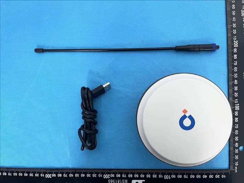
Click to zoom
Application Details
- Equipment Class
- DTS - Digital Transmission System
- Date of Grant
- May 16, 2023
- Application Purpose
- Original Equipment
- Date of Application
- May 16, 2023
- Equipment Note
- GNSS Receiver
- Frequency Range
- 2412.00000000 - 2462.00000000
- Country
- China
Documents & Files
Document Text
Text extracted from the exhibit documents filed with the FCC. Open a document above to read the original.
Users Manual
Qianxun SI RTK Quick Start 【 Product Introduction 】 The Qianxun SI Survey RTK product suite consists of a Qianxun SI Survey RTK Receiver and related accessories. Note: This instruction is applicable to Q300 and Q600 products. Indicator Description: Indicator Light Satellite Status Blue light flashes when searching for stars, always on after finishing positioning Power Status Power light blinks when the power is <10% Data Status Green light blinks 1s for differential data in dynamic RTK mode Static mode blinks at sampling frequency interval Key Description: Key Startup & Shutdown Press and hold for 3s to turn on, long press for 3s to turn off Inquiry Click the key to check the battery status Mode Switch Double-click the button to switch modes and click to confirm [ Turn on the device ] It is suggested to charge the device for the first time before using it. Turn on the RTK host and controller → Press the "APP" button in the controller to start the measurement software. The first time you use it, a privacy agreement will pop up, accept it and use it. [Connecting Instruments] Click the device icon button in the upper right corner of the app to enter the device connection interface. In the device connection interface, you can choose to conn ect the device after using Wi-Fi search, as in Figure 1. Note: Qianxun SI survey RTK products start with "QX" by default, such as QX21000034 【 Activation 】 Host Registration When you use the device for the first time, you need to use the registration code to open the authorization to use the device. Please apply for the registration code from the distributor who purchased the device. Registration method: App upper right corner device icon → click [Device] in the device information after the [Regist] button can be entered, prompt Service Activation If you have purchased a star-based service, you need to use the authorization code to open it in order to achieve high-precision positioning operation without network on a single device. In the device information, you can click the [Regist] button after [XStar] to activate the star-based service, please consult the manufacturer's technical staff for service coverage. Star- based service needs to update the key file once every six months, and you can select the locally imported key file by [Select file]. [New Project] When you enter the App, Qianxun SI has automatically created a project for you. The default project name is controller system time, the coordinate system is WGS84, the projection is horizontal axis Mokato If necessary, you can go to the left menu bar to create a new project or modify the project information and the required coordinate system parameters, as in Figure-2. Figure-2 [Data Import] In the point library, you can select the required data format and file to import data, as shown in Figure 3- 6. [Work Mode Configuration] The first time you turn on the machine, it will automatically enable "Radio", you can directly carry out survey operations. If there is no network on site or you have other needs, you can configure as follows: Enter the device configuration interface through the left menu bar → [Device Config] You can configure rover station, base station and static station as required. Create Rover Station Mode Click the [Create] button, [Type] select [Rover], and choose the data chain mode. Radio: Some models have radio function, at this time you need another RTK to be the Base station and broadcast differential data to the mobile station via radio for measurement operation. This mode is suitable for all outdoor work scenarios. Star -based: Some models are equipped with star-based function. Star-based service does not depend on network and does not need to set up a reference station, and can achieve centimeter- level positioning by a single machine. The satellite-based service needs to be opened according to the area, and high-precision operation can be realized within the coverage of the satellite-based, please consult customer service or authorized distributors for details. Create Base Station Mode Some models have base station function. Click [Create] button, [Type] select [Base], configure radio related parameters and click OK to finish the configuration. If there is a known point, you can select [Known Point] mode, enter the ground point coordinates and antenna slope height to start, as in Figure- 8. Create Static Station Mode Static station mode is used for control network deployment and control point encryption. Click the [Create] button, select [Static] for [Type], and configure the relevant parameters to complete the configuration. The default sample interval is 10s and the default file format is RINEX3.02, as shown in Figure 9. 【 Survey】 Menu bar on the left → [Survey], the main interface switches to point measurement mode. In the point measurement mode, you can select the first configuration button in the right toolbar of the interface to configure the required measurement parameters, as shown in Figure-10. In the main interface, you can switch the type of measurement points ( Control Point, Continuous Point, Rapid Point, Topographic Point, Eccentric Point), enter the required number of observation points and other parameters, and then click [Start survey] to collect the required type of points, as shown in Figure- 11. [Parameter Calculation] Point Correction The first time you go to a survey area, you need to do point correction if you want the measured point to match the known point coordinates. If you are using Qianxun SI network operation mode and your project coordinates match the CGCS2000 coordinates broadcasted by Qianxun SI, you can skip this step. The left menu bar → [CRS] → [Site Calib], you can enter the point correction parameter calculation interface, as in Figure- 12. Select the plane coordinates of known points in N pairs of survey area and the latitude and longitude coordinates under the ellipsoid corresponding to known points, click [Calculate] to solve the plane …
Text truncated - open the document above for the full version.
Attestation Statements
Qianxun Spatial Intelligence (Zhejiang) Inc. CFR 47 §2.911(d)(5)(i)(ii) Attestation Letter Attestation Letter Date: 03/02/2023 FEDERAL COMMUNICATIONS COMMISSIONS Authorization and Evaluation Division 7435 Oakland Mills Road Columbia, MD 21046 Ref: Attestation Statements CFR 47 §2.911(d)(5)(i)(ii) Filing FCC ID: 2A33X-Q300 Qianxun Spatial Intelligence (Zhejiang) Inc. (“the applicant”) certifies that the equipment for which authorization is sought is not “covered” equipment prohibited from receiving an equipment authorization pursuant to section 2.903 of the FCC rules. Qianxun Spatial Intelligence (Zhejiang) Inc. (“the applicant”) certifies that as of the date of the filing of the application, the applicant is not identified on the Covered List as an entity producing “covered” equipment. Sincerely, Signature Contact Person: Yong Zhou Title: Senior Test Specialist Company Name & Address: Qianxun Spatial Intelligence (Zhejiang) Inc./ No.1,Building12,Area C,Deqing Geographic Info Town, Wuyang Street,Deqing County,Huzhou City,Zhejiang Province, China
Cover Letter(s)
QA-FR-170-B Qianxun Spatial Intelligence (Zhejiang) Inc. ADD: No.1,Building12,Area C,Deqing Geographic Info Town, Wuyang Street,Deqing County, Huzhou City,Zhejiang Province, China TEL: +86-18682098095 FAX: +86 021 61409551 E-mail: [email protected] FCC Authorization Date: 2023-03-02 FEDERAL COMMUNICATIONS COMMISSION Authorization and Evaluation Division 7435 Oakland Mills Road Columbia, MD 21046 Subject: Agent Authorization To whom it may concern: We , Qianxun Spatial Intelligence (Zhejiang) Inc., Hereby authorizes China Certification ICT Co., Ltd (Dongguan) to act on its behalf in all matters relating to application for Equipment authorization, including the signing of all documents relating to these matters. All acts carried out by China Certification ICT Co., Ltd (Dongguan) on our behalf shall have the same effect as our own action. We, the undersigned, hereby certify that we are not subject to a denial of federal benefits, that includes FCC benefits, pursuant to Section 5301 of the Anti-Drug Abuse Act of 1988, 21 U.S.C. 862. This authorization is valid until further written notice from the applicant. Sincerely Yours, Client’s signature QA-FR-170-B Printed Name: Yong Zhou Title: Senior Test Specialist
Cover Letter(s)
QA-FR-171-A Qianxun Spatial Intelligence (Zhejiang) Inc. ADD:No.1,Building12,Area C,Deqing Geographic Info Town, Wuyang Street,Deqing County,Huzhou City,Zhejiang Province, China TEL: +86-18682098095 FAX: +86 021 61409551 E-mail: [email protected] FCC Confidential Authorization Date: 2023-03-02 FEDERAL COMMUNICATIONS COMMISSIONS Authorization and Evaluation Division 7435 Oakland Mills Road Columbia, MD 21046 Subject: Confidentiality Request regarding application for certification of FCC ID: 2A33X-Q300 In accordance with Sections 0.457 and 0.459 of the Commission’s Rules, (Qianxun Spatial Intelligence (Zhejiang) Inc.) hereby requests long-term confidential treatment of information accompanying this application as outlined below: Block Diagram Schematics Operation Description The above materials contain proprietary and confidential information not customarily released to the public. The public disclosure of these materials provides unjustified benefits to its competitors in the market. Sincerely, Signature: Printed Name: Yong Zhou Title: Senior Test Specialist
External Photos
EXHIBIT B - EUT EXTERNAL PHOTOGRAPHS Port Port
Internal Photos
EXHIBIT C - EUT INTERNAL PHOTOGRAPHS Uncover Chip Chip Chip Chip Chip Chip Chip GNSS Radio Path BT/Wi-Fi Radio Path WWAN Radio Path (option) Antennas RX Antenna (RTK radio) WWAN Antenna (Option) BT/Wi-Fi Antenna GNSS Antenna
RF Exposure Info
China Certification ICT Co., Ltd (Dongguan) Report No.: CR230208803-00C Page 43 of 43 5. RF EXPOSURE EVALUATION 5.1 Applicable Standard FCC §15.247 (i) Systems operating under the provisions of this section shall be operated in a manner that ensures that the public is not exposed to radio frequency energy levels in excess of the Commission's guidelines. See §1.1307(b)(1) of this chapter. 5.2 Procedure According to §1.1307(b)(3)(i) (C) Or using Table 1 and the minimum separation distance (R in meters) from the body of a nearby person for the frequency (f in MHz) at which the source operates, the ERP (watts) is no more than the calculated value prescribed for that frequency. For the exemption in Table 1 to apply, R must be at least λ/2π, where λ is the free-space operating wavelength in meters. If the ERP of a single RF source is not easily obtained, then the available maximum time-averaged power may be used in lieu of ERP if the physical dimensions of the radiating structure(s) do not exceed the electrical length of λ/4 or if the antenna gain is less than that of a half-wave dipole (1.64 linear value). Table 1 to § 1.1307(b)(3)(i)(C) - Single RF Sources Subject to Routine Environmental Evaluation 113333 Threshold ERP (watts) 0.3-1.34 1,920 R 2 . 1.34-30 3,450 R 2 /f 2 . 30-300 3.83 R 2 . 300-1,500 0.0128 R 2 f. 1,500-100,000 19.2R 2 . 5.3 Measurement Result Radio Frequency (MHz) λ/2 Π (mm) Distance (mm) Exemption ERP (mW) Maximum Conducted Power including Tune-up Tolerance (dBm) Antenna Gain (dBi) ERP MPE- Based Exemption dBm mW WiFi 2412-2462 19.80 200 768 23 3.87 24.72 296.48 Compliant BLE 2402-2480 19.88 200 768 4 3.87 5.72 3.73 Compliant BDR/EDR 2402-2480 19.88 200 768 3 3.87 4.72 2.96 Compliant Note: The Bluetooth and WiFi can’t transmit simultaneously. The Conducted output power including Tune-up Tolerance was provided by applicant Result: The device compliant the MPE-Based Exemption at 20cm distances. ===== END OF REPORT ====
Test Report
Q300 Antenna QX-A910 Specification 1. Key Feature 1). This antenna is with full frequency point of GPS/BEIDOU/GLONASS/GALILEO,BT/WIFI 4G signal reception capability, integrated design. 2). The passive part of the antenna adopts multi-feed point design scheme to ensure the coincidence of phase center and geometric center, which effectively improves the phase center stability of the antenna. 3). Reliable phase center, low elevation signal tracking, and high signal gain offer millimeter position. 4). Great electromagnetic compatibility, easy for integration. 2. QX-910 Performance Antenna Specification Frequency Band BDS B1/ GPS L1 GLONASS G1 GALILEO E1/E2 L_Band(1525M~1550M) BDS B2/B3 GPS L2/L5 GLONASS G2 GALILEO E5a/E5b Bluetooth : 2402~2480MHz WIFI : 2412~2462MHz 2G/3G/4G PolarizationRHCP// Max Gain/Efficiency 4.2dBi4.7dBi3.87dBi Typ: 20~50% Output Impedance50Ω VSWRTyp≤2, max<3≤2Typ≤4 Circular polarization axis ratio ≤3dB/ Horizontal range360 o 360 o Phase Center Stability±2mm/ LNA Flatness in the band≤±1dB/ Input voltage3.3~12V/ Current≤50mA/ Noise figure≤1.8dB/ Environment Operation temp.-40°~ +85°C Storage temp.-55°~ +85°C Humidity95% Non-condensing 3. Dimension 4. Antenna orientation diagram and Axial Ratio 4.1 L1 Frequency 4.2 L2 Frequency 4.3 BT/WIFI 5. Antenna Efficiency 5.1 GNSS Antenna Frequency(MHz) EfficiencyRHCP Gain (dBi) 1160 40%3.134469 1165 43%3.410471 1170 45%3.700392 1175 49%4.039441 1180 53%4.368795 1185 56%4.587912 1190 58%4.781476 1195 60%4.927579 1200 62%5.027958 1205 65%5.255068 1210 67%5.406822 1215 70%5.580892 1220 71%5.674845 1225 70%5.655666 1230 69%5.63626 1235 68%5.607775 1240 67%5.595894 1245 67%5.68955 1250 67%5.706408 1255 66%5.649847 1260 65%5.598963 1265 61%5.315293 1270 58%5.078583 1275 55%4.864292 1280 53%4.654486 1285 52%4.65777 1290 52%4.637341 1520 41%2.773583 1525 43%3.105183 1530 45%3.428458 1535 48%3.687885 1540 50%3.917413 1545 52%4.061545 1550 53%4.200051 1555 53%4.186495 1560 53%4.18374 1565 53%4.214208 1570 53%4.32756 1575 54%4.473828 1580 55%4.618537 1585 54%4.649304 1590 54%4.652438 1595 52%4.511874 1600 50%4.344348 1605 49%4.239414 1610 48%4.175889 1615 47%4.1258 1620 46%4.025725 5.2 BT/WIFI Antenna Frequency(MHz ) EfficiencyGain(dBi) 2400 71%2.304004 2405 72%2.398894 2410 72%2.476124 2415 71%2.45508 2420 71%2.622092 2425 72%2.881636 2430 71%3.038691 2435 71%3.248291 2440 71%3.364268 2445 71%3.522629 2450 72%3.690536 2455 72%3.830902 2460 72%3.869493 2465 71%3.846188 2470 71%3.848527 2475 71%3.833516 2480 70%3.783053 2485 71%3.784878 2490 70%3.707722 2495 70%3.725527 2500 70%3.626609
Test Report
TEST REPORT Applicant: Qianxun Spatial Intelligence (Zhejiang) Inc. Address: No.1,Building12,Area C, Deqing Geographic Info Town, Wuyang Street, Deqing County, Huzhou City, Zhejiang Province, China FCC ID: 2A33X-Q300 Product Name: GNSS Receiver Standard(s): 47 CFR Part 15, Subpart C(15.247) ANSI C63.10-2013 KDB 558074 D01 15.247 Meas Guidance v05r02 The above equipment has been tested and found compliant with the requirement of the relative standards by China Certification ICT Co., Ltd (Dongguan) Report Number: CR230208803-00D Date Of Issue: 2023/5/10 Reviewed By: Sun Zhong Title: Manager Test Laboratory: China Certification ICT Co., Ltd (Dongguan) No. 113, Pingkang Road, Dalang Town, Dongguan, Guangdong, China Tel: +86-769-82016888 China Certification ICT Co., Ltd (Dongguan) Report No.: CR230208803-00D Page 2 of 52 Test Facility The Test site used by China Certification ICT Co., Ltd (Dongguan) to collect test data is located on the No. 113, Pingkang Road, Dalang Town, Dongguan, Guangdong, China. The lab has been recognized as the FCC accredited lab under the KDB 974614 D01 and is listed in the FCC Public Access Link (PAL) database, FCC Registration No. : 442868, the FCC Designation No. : CN1314. The lab has been recognized by Innovation, Science and Economic Development Canada to test to Canadian radio equipment requirements, the CAB identifier: CN0123. Declarations China Certification ICT Co., Ltd (Dongguan) is not responsible for the authenticity of any test data provided by the applicant. Data included from the applicant that may affect test results are marked with a triangle symbol “▲”. Customer model name, addresses, names, trademarks etc. are not considered data. Unless otherwise stated the results shown in this test report refer only to the sample(s) tested. This report cannot be reproduced except in full, without prior written approval of the Company. This report is valid only with a valid digital signature. The digital signature may be available only under the Adobe software above version 7.0. This report may contain data that are not covered by the accreditation scope and shall be marked with an asterisk “★”. China Certification ICT Co., Ltd (Dongguan) Report No.: CR230208803-00D Page 3 of 52 CONTENTS T EST FACILITY .......................................................................................................................................... 2 DECLARATIONS .......................................................................................................................................... 2 DOCUMENT REVISION HISTORY .......................................................................................... 5 1. GENERAL INFORMATION .................................................................................................... 6 1.1 PRODUCT DESCRIPTION FOR EQUIPMENT UNDER TEST (EUT) ....................................................... 6 1.2 DESCRIPTION OF TEST CONFIGURATION ........................................................................................... 8 1.2.1 EUT Operation Condition: ............................................................................................................................. 8 1.2.2 Support Equipment List and Details .............................................................................................................. 8 1.2.3 Support Cable List and Details ...................................................................................................................... 8 1.2.4 Block Diagram of Test Setup ......................................................................................................................... 9 1.3 MEASUREMENT UNCERTAINTY ........................................................................................................ 10 2. SUMMARY OF TEST RESULTS .......................................................................................... 11 3. REQUIREMENTS AND TEST PROCEDURES .................................................................. 12 3.1 AC LINE CONDUCTED EMISSIONS .................................................................................................... 12 3.1.1 Applicable Standard ..................................................................................................................................... 12 3.1.2 EUT Setup.................................................................................................................................................... 13 3.1.3 EMI Test Receiver Setup ............................................................................................................................. 13 3.1.4 Test Procedure ............................................................................................................................................. 14 3.1.5 Corrected Amplitude & Margin Calculation ................................................................................................ 14 3.2 RADIATION SPURIOUS EMISSIONS .................................................................................................... 15 3.2.1 Applicable Standard ..................................................................................................................................... 15 3.2.2 EUT Setup.................................................................................................................................................... 15 3.2.3 EMI Test Receiver & Spectrum Analyzer Setup ......................................................................................... 16 3.2.4 Test Procedure ............................................................................................................................................. 16 3.2.5 Corrected Amplitude & Margin Calculation ................................................................................................ 16 3.3 6 DB EMISSION BANDWIDTH: ..................................................................…
Text truncated - open the document above for the full version.
Test Report
TEST REPORT Applicant: Qianxun Spatial Intelligence (Zhejiang) Inc. Address: No.1,Building12,Area C, Deqing Geographic Info Town, Wuyang Street, Deqing County, Huzhou City, Zhejiang Province, China FCC ID: 2A33X-Q300 Product Name: GNSS Receiver Standard(s): 47 CFR Part 15, Subpart C(15.247) ANSI C63.10-2013 KDB 558074 D01 15.247 Meas Guidance v05r02 The above equipment has been tested and found compliant with the requirement of the relative standards by China Certification ICT Co., Ltd (Dongguan) Report Number: CR230208803-00C Date Of Issue: 2023/4/3 Reviewed By: Sun Zhong Title: Manager Test Laboratory: China Certification ICT Co., Ltd (Dongguan) No. 113, Pingkang Road, Dalang Town, Dongguan, Guangdong, China Tel: +86-769-82016888 China Certification ICT Co., Ltd (Dongguan) Report No.: CR230208803-00C Page 2 of 43 Test Facility The Test site used by China Certification ICT Co., Ltd (Dongguan) to collect test data is located on the No. 113, Pingkang Road, Dalang Town, Dongguan, Guangdong, China. The lab has been recognized as the FCC accredited lab under the KDB 974614 D01 and is listed in the FCC Public Access Link (PAL) database, FCC Registration No. : 442868, the FCC Designation No. : CN1314. The lab has been recognized by Innovation, Science and Economic Development Canada to test to Canadian radio equipment requirements, the CAB identifier: CN0123. Declarations China Certification ICT Co., Ltd (Dongguan) is not responsible for the authenticity of any test data provided by the applicant. Data included from the applicant that may affect test results are marked with a triangle symbol “▲”. Customer model name, addresses, names, trademarks etc. are not considered data. Unless otherwise stated the results shown in this test report refer only to the sample(s) tested. This report cannot be reproduced except in full, without prior written approval of the Company. This report is valid only with a valid digital signature. The digital signature may be available only under the Adobe software above version 7.0. This report may contain data that are not covered by the accreditation scope and shall be marked with an asterisk “★”. China Certification ICT Co., Ltd (Dongguan) Report No.: CR230208803-00C Page 3 of 43 CONTENTS T EST FACILITY .......................................................................................................................................... 2 DECLARATIONS .......................................................................................................................................... 2 DOCUMENT REVISION HISTORY .......................................................................................... 5 1. GENERAL INFORMATION .................................................................................................... 6 1.1 PRODUCT DESCRIPTION FOR EQUIPMENT UNDER TEST (EUT) ....................................................... 6 1.2 DESCRIPTION OF TEST CONFIGURATION ........................................................................................... 7 1.2.1 EUT Operation Condition: ............................................................................................................................. 7 1.2.2 Support Equipment List and Details .............................................................................................................. 7 1.2.3 Support Cable List and Details ...................................................................................................................... 7 1.2.4 Block Diagram of Test Setup ......................................................................................................................... 7 1.3 MEASUREMENT UNCERTAINTY .......................................................................................................... 9 2. SUMMARY OF TEST RESULTS .......................................................................................... 10 3. REQUIREMENTS AND TEST PROCEDURES .................................................................. 11 3.1 AC LINE CONDUCTED EMISSIONS .................................................................................................... 11 3.1.1 Applicable Standard ..................................................................................................................................... 11 3.1.2 EUT Setup.................................................................................................................................................... 12 3.1.3 EMI Test Receiver Setup ............................................................................................................................. 12 3.1.4 Test Procedure ............................................................................................................................................. 13 3.1.5 Corrected Amplitude & Margin Calculation ................................................................................................ 13 3.2 RADIATION SPURIOUS EMISSIONS .................................................................................................... 14 3.2.1 Applicable Standard ..................................................................................................................................... 14 3.2.2 EUT Setup.................................................................................................................................................... 14 3.2.3 EMI Test Receiver & Spectrum Analyzer Setup ......................................................................................... 15 3.2.4 Test Procedure ............................................................................................................................................. 15 3.2.5 Corrected Amplitude & Margin Calculation ................................................................................................ 15 3.3 6 DB EMISSION BANDWIDTH: ..................................................................…
Text truncated - open the document above for the full version.
Test Setup Photos
EXHIBIT D - TEST SETUP PHOTOGRAPHS Conducted Emissions Front View Conducted Emissions Side View Radiated Emission Below 1GHz View Radiated Emission Above 1GHz View
Contact Information
Applicant
Yong Zhou(Senior Test Specialist)
Test Firm
CHINA CERTIFICATION ICT CO., LTD (DONGGUAN)Tanie Ou
[email protected]0086 0769 86858888
Technical Specifications
| # | Rule Parts | Frequency Range | Power Output |
|---|---|---|---|
| 2 | 15C | 2.41 GHz - 2.46 GHz | 182.00 mW |
Other Applications from Qianxun Spatial Intelligence (Zhejiang) Inc.
2A33X-HC6
Apr 12, 2023Handheld data collection terminal
Equipment Class
TNT - Licensed Non-Broadcast Transmitter Worn on Body