2A3CE-LP5B-A1AOR Battery Wi-Fi Camera
Longse Technology Limited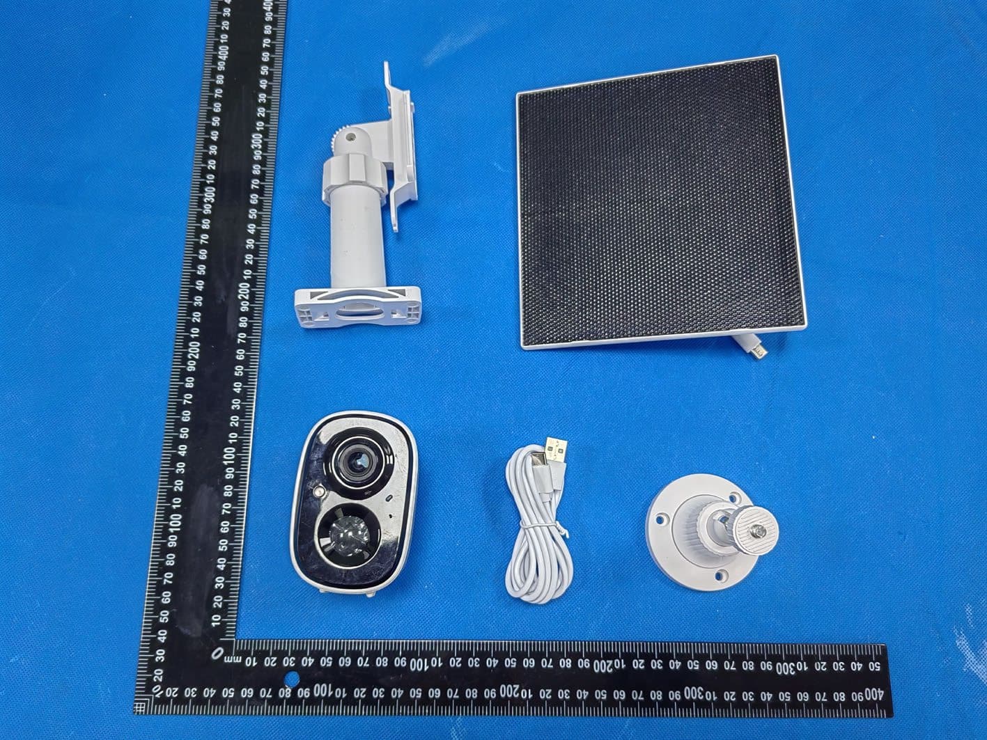
Click to zoom
Application Details
- Equipment Class
- DTS - Digital Transmission System
- Date of Grant
- Apr 24, 2026
- Application Purpose
- Original Equipment
- Equipment Note
- AOR Battery Wi-Fi Camera
- Frequency Range
- 2412.00000000 - 2462.00000000
- Company
- Longse Technology Limited
- Country
- China
Documents & Files
Document Text
Text extracted from the exhibit documents filed with the FCC. Open a document above to read the original.
Users Manual
1.1 Download App 1.2 Register and Log in to the App Users can register an App account using a phone number or email. After completing registration, they will be automatically logged in. Or they can log in with third-party accounts such as WeChat or Apple. Method 1: Scan the QR code below with your mobile phone to download and install the App. Method 2:Search for “LongVision”in major app stores, locate the LongVision App, and click to download it. Scan the QR code to download “LongVision” APP (*WiFi devices do not require a SIM card) SD/TF Card Slot: To view local recordings, open the card slot cover before installation and correctly insert the SD/TF card. Reset Button: To restore factory settings, open the card slot cover on the back of the device and press and hold the reset button for 3-5 seconds. Power Button: The device is powered off by default. Press and hold the power button for 3 seconds to turn on, or for 10 seconds to turn off. Type-C Port: Charge the battery by connecting a DC 5V&1A power adapter or the solar panel's Type-C charging cable to this port. PIR Human Sensor: The default mode of the device when shipped from the factory relies on PIR human infrared sensing to trigger and wake up the device for video recording. Please refer to the detection distance below, and try to aim the device toward the monitoring area. The device is powered off by default. Press and hold the power button for 3 seconds to turn it on. A voice prompt will confirm successful startup. 。 Fully charge the battery before first use with a 5V&1A power adapter. The charging indicator will glow solid red during charging. It turns off when fully charged. Tap the "+" button in the top-right corner of the App home screen. Select "Add WiFi Camera" or "Scan QR code on device body" and follow the in-app instructions to configure the network. 1 After confirming the camera announces "Connection Complete", proceed to complete adding the camera. Follow these steps to install an SD/TF card for local recording: STEP 1: Open the card slot cover on the bottom of the camera to locate the SD/TF card slot. STEP 2: Orient the SD/TF card correctly and carefully insert it into the slot. Push the card in until you hear a click. Quick Start Guide *Go to Camera Settings > SD Card Recording in the SV360 App to check card status or format the card. Step 1: Drill holes according to the mounting sticker and install the bracket base onto the wall. Step 2: Install the threaded of the bracket base onto the camera. Step 3: Adjust the camera angle for optimal view, then tighten the bracket knob clockwise to complete installation. Step 1: Based on the bracket's through-hole positions, drill pilot holes in the wall, insert plastic expansion tubes, pass self-tapping screws through the bracket's through-holes, and secure the solar panel bracket to a sun-facing wall. Self-tapping Screws Plastic Expansion Step 2: Align the solar panel with the bracket's snap-fit position and snap the panel into the bracket from top to bottom. Step 3: Adjust the solar panel angle using the large knob on the bracket to maximize light exposure area and duration based on local sunlight conditions. Then connect the Type-C power supply interface on the solar panel to the corresponding interface on the camera to complete installation. Large Knob Type-C Power Supply Interface The operating temperature range of the camera is -10°C to 50°C.Do not use the camcorder in temperatures above or below thespecified range. Do not allow children or pets to chew on the camera or its accessories,as this may cause injury to them or result in equipment failure. For better image results, do not point the lens towards or nearreflec- tive surfaces such as glass windows or white walls, as this maycause the image to appear too bright in areas close to the camera anddarker in areas farther away, or cause the camera to produce a whiteout effect. Make sure the camera is installed in an area with a strong Wi-Fi signal.Do not place the camera near objects that may affect its Wi-Fi signal,such as metal objects and microwave ovens. When installing the camera, follow the installation guidelines to securelyfasten the camera to the wall or ceiling to avoid the camera falling offand causing damage. * If you have further questions, please contact the sales store or reach out to us via the “My-Feedback” channel in the app. *Images are for reference only, please refer to the actual product. determined by turning the equipment off and on, the user is encouraged to try to correct the interference by one or more of the following measures: > Reorient or relocate the receiving antenna. > Increase the separation between the equipment and receiver. > Connect the equipment into an outlet on a circuit different from that to which the receiver is connected. > Consult the dealer or an experienced radio/TV technician for help. This equipment complies with FCC radiation exposure limits set forth for an uncontrolled environment. This equipment should be installed and operated with minimum distance 20cm between the radiator & your body. This device complies with part 15 of the FCC Rules. Operation is subject to the following two conditions: (1) This device may not cause harmful interference, and (2) this device must accept any interference received, including interference that may cause undesired operation. Any Changes or modifications not expressly approved by the party responsible for compliance could void the user's authority to operate the equipment. Note: This equipment has been tested and found to comply with the limits for a Class B digital device, pursuant to part 15 of the FCC Rules. These limits are designed to provide reasonable protection against harmful interference in a residential installation. This equipment generates uses and can radiate radio frequency energy and, if not installed and used in accordance with the instructions, may cause harmful interference to radio communications. However, there is …
Text truncated - open the document above for the full version.
Attestation Statements
Longse Technology Limited 2026.04.15 Eurofins Electrical and Electronic Testing NA, Inc. 914 West Patapsco Avenue Baltimore, MD 21230 RE: Attestation Statements Part 2.911(d)(5)(i) request for FCC ID: 2A3CE-LP5B-A1 [Longse Technology Limited] certifies that the equipment for which authorization is sought is not “covered” equipment prohibited from receiving an equipment authorization pursuant to section 2.903 of the FCC rules. We also certify that, as of the date of the filing of the application, the equipment does not utilize cyber-security or anti-virus software from Kaspersky Lab, Inc, or any of its successors and assignees, which is also on the “covered list”. Sincerely, (Applicant signature) (Applicant printed name) HE HAIEN Longse Technology Limited 2026.04.15 Eurofins Electrical and Electronic Testing NA, Inc. 914 West Patapsco Avenue Baltimore, MD 21230 RE: Attestation Statements Part 2.911(d)(5)(ii) request for FCC ID: 2A3CE-LP5B-A1 [Longse Technology Limited] certifies that, as of the date of the filing of the application, the applicant is not identified on the Covered List as an entity producing “covered” equipment. Sincerely, (Applicant signature) (Applicant printed name) HE HAIEN
Cover Letter(s)
Longse Technology Limited 2026.04.15 Eurofins Electrical and Electronic Testing NA, Inc. 914 W. Patapsco Avenue Baltimore, MD 21230 USA RE: CONFIDENTIALITY REQUEST FOR EUT NAME: AOR Battery Wi-Fi Camera MODEL: LP5B-A1, LP2B-A1, LP2B-A2, LP2B-A3, LP2B-A4, LP4B-A1, LP4B-A2, LP4B-A3, LP4B-A4, LP5B-A2, LP5B-A3, LP5B-A4, LP8B-A1, LP8B-A2, LP8B-A3, LP8B-A4, LP2B-B1, LP2B-B2, LP2B-B3, LP2B-B4, LP4B-B1, LP4B-B2, LP4B-B3, LP4B-B4, LP5B-B1, LP5B-B2, LP5B-B3, LP5B-B4, LP8B-B1, LP8B-B2, LP8B-B3, LP8B-B4, LPXB-XX, stands for letters to describe the shape of the appearance. FCC ID: 2A3CE-LP5B-A1 To Whom It May Concern: This letter serves as an official request for confidentiality under sections 0.457 and 0.459 of CFR 47. We have requested that the - Block Diagram - Schematics - Operational Description - FCC Software Security Requirements for UNII devices required to be submitted with this application be permanently withheld from public review. The above materials contain trade secrets and proprietary information not customarily released to the public. The public disclosure of these materials may be harmful to the applicant and provide unjustified benefits to its competitors. Please contact me if there is any information you may need. Sincerely, Client’s signature: Client’s name / title: HE HAIEN Contact information / address: No.18, Dongming 3rd, Huangpu District, Guangzhou, Guangdong, China
Cover Letter(s)
Longse Technology Limited 2026.04.15 Eurofins Electrical and Electronic Testing NA, Inc. 914 W. Patapsco Avenue Baltimore, MD 21230 USA RE: LETTER OF AGENT AUTHORIZATION To Whom It May Concern: We, the undersigned, hereby authorize SHENZHEN STS TEST SERVICES CO.,LTD. to act on our behalf in all matters relating to application for equipment authorization, including the signing of all documents relating to these matters. We also hereby certify that no party to the application authorized hereunder is subject to the denial of benefits, including FCC benefits, pursuant to Section 5301 of the Anti-Drug Abuse Act of 1988, 21 U.S.C.853(a). This agreement expires one year from the current date. Sincerely, Client’s signature: Client’s name / title: HE HAIEN Contact information / address: No.18, Dongming 3rd, Huangpu District, Guangzhou, Guangdong, China
Cover Letter(s)
Longse Technology Limited Model Difference EUT NAME: AOR Battery Wi-Fi Camera MODEL: LP5B-A1, LP2B-A1, LP2B-A2, LP2B-A3, LP2B-A4, LP4B-A1, LP4B-A2, LP4B-A3, LP4B-A4, LP5B-A2, LP5B-A3, LP5B-A4, LP8B-A1, LP8B-A2, LP8B-A3, LP8B-A4, LP2B-B1, LP2B-B2, LP2B-B3, LP2B-B4, LP4B-B1, LP4B-B2, LP4B-B3, LP4B-B4, LP5B-B1, LP5B-B2, LP5B-B3, LP5B-B4, LP8B-B1, LP8B-B2, LP8B-B3, LP8B-B4, LPXB-XX, stands for letters to describe the shape of the appearance. FCC ID: 2A3CE-LP5B-A1 All the model are the same circuit and RF module, except model names. Regards Sincerely Client’s signature: Client’s name / title: HE HAIEN Contact information / address: 3rd Floor, Bingding A, No.1 Jiangxing Road, Huangjiang Village, Huangjiang Town, Dongguan City, Guangdong Province China
External Photos
External Photos
ID Label/Location Info
50*30mm Label Location FCC ID: 2A3CE-LP5B-A1
Internal Photos
Internal Photos Antenna
RF Exposure Info
The test results presented in this report relate only to the object tested. This report shall not be reproduced, except in full, without the written approval of the ShenZhen STS Test Services Co., Ltd. MPE Report Report No.:STS2604398H01 Issued for Longse Technology Limited No.18, Dongming 3rd, Huangpu District, Guangzhou, Guangdong, China Product Name: AOR Battery Wi-Fi Camera Brand Name: N/A Model Name: LP5B-A1 Series Model(s): See P2 FCC ID: 2A3CE-LP5B-A1 Test Standard: FCC 47CFR §2.1091 Page 2 of 7 Report No.: STS2604398H01 TEST REPORT Applicant’s Name ................. : Longse Technology Limited Address ................................. : No.18, Dongming 3rd, Huangpu District, Guangzhou, Guangdong, China Manufacturer's Name ........... : Longse Technology Limited Address ................................. : No.18, Dongming 3rd, Huangpu District, Guangzhou, Guangdong, China Product Description Product Name ........................ : AOR Battery Wi-Fi Camera Brand Name .......................... : N/A Model Name .......................... : LP5B-A1 Series Model(s) ...................... : LP2B-A1, LP2B-A2, LP2B-A3, LP2B-A4, LP4B-A1, LP4B-A2, LP4B-A3, LP4B-A4, LP5B-A2, LP5B-A3, LP5B-A4, LP8B-A1, LP8B-A2, LP8B-A3, LP8B-A4, LP2B-B1, LP2B-B2, LP2B-B3, LP2B-B4, LP4B-B1, LP4B-B2, LP4B-B3, LP4B-B4, LP5B-B1, LP5B-B2, LP5B-B3, LP5B-B4, LP8B-B1, LP8B-B2, LP8B-B3, LP8B-B4, LPXB-XX, stands for letters to describe the shape of the appearance. Test Standards ..................... : FCC 47CFR §2.1091 447498 D01 Interim General RF Exposure Guidance v06 The test results presented in this report relate only to the object tested. This report shall not be reproduced, except in full, without the written approval of the ShenZhen STS Test Services Co., Ltd. Date of Test ........................................... : Date of receipt of test item ...................... : 2026-01-08 Date (s) of performance of tests ............. : 2026-01-09 to 2026-02-13 Date of Issue .......................................... : 2026-03-03 Test Result .............................................. : Pass Testing Engineer : (Aaron Bu) Technical Manager : (Skylar Li) Authorized Signatory : (Bovey Yang) Page 3 of 7 Report No.: STS2604398H01 TABLE OF CONTENTS 1. GENERAL INFORMATION 5 1.1 GENERAL DESCRIPTION OF THE EUT 5 1.2 TEST FACTORY 5 2. FCC 47CFR §2.1091 REQUIREMENT 6 2.1 TEST STANDARDS 6 2.2 LIMIT 6 2.3 TEST RESULT 7 Page 4 of 7 Report No.: STS2604398H01 Revision History Rev. Issue Date Report No. Effect Page Contents 00 2026-03-03 STS2604398H01 ALL Initial Issue Page 5 of 7 Report No.: STS2604398H01 1. GENERAL INFORMATION 1.1 GENERAL DESCRIPTION OF THE EUT Product Name AOR Battery Wi-Fi Camera Brand Name N/A Model Name LP5B-A1 Series Model(s) LP2B-A1, LP2B-A2, LP2B-A3, LP2B-A4, LP4B-A1, LP4B-A2, LP4B-A3, LP4B-A4, LP5B-A2, LP5B-A3, LP5B-A4, LP8B-A1, LP8B-A2, LP8B-A3, LP8B-A4, LP2B-B1, LP2B-B2, LP2B-B3, LP2B-B4, LP4B-B1, LP4B-B2, LP4B-B3, LP4B-B4, LP5B-B1, LP5B-B2, LP5B-B3, LP5B-B4, LP8B-B1, LP8B-B2, LP8B-B3, LP8B-B4, LPXB-XX, stands for letters to describe the shape of the appearance. Model Difference All the model are the same circuit and RF module, except model names. Product Description The EUT is WIFI Video Doorbell Operation Frequency: 2412-2462MHz Modulation Type: DSSS, OFDM Antenna Type: FPC antenna Antenna Gain: 2.26 dBi Power Rating DC 3.7V From Battery, DC 5V From Adapter / Solar Adapter NA Battery DC 3.7V 1.2 TEST FACTORY SHENZHEN STS TEST SERVICES CO., LTD Add. : 101, Building B, Zhuoke Science Park, No.190 Chongqing Road, ZhanChengShequ, Fuhai Sub-District, Bao’an District, Shenzhen, Guang Dong, China FCC test Firm Registration Number: 625569 IC test Firm Registration Number: 12108A A2LA Certificate No.: 4338.01 Page 6 of 7 Report No.: STS2604398H01 2. FCC 47CFR §2.1091 REQUIREMENT 2.1 TEST STANDARDS The limit for Maximum Permissible Exposure (MPE) specified in FCC 1.1310 is followed. The gain of the antennas used in the product is extracted from the Antenna data sheets provided and also the maximum total power input to the antenna is measured. Through the Friis transmission formula and the maximum gain of the antenna, we can calculate the distance, away from the product, where the limit of MPE is reached. Although the Friis Transmission formula is far field assumption, the calculated result of that is an over-prediction for near field power density. It is taken as worst case to specify the safety range. 2.2 LIMIT According to FCC 1.1310: The criteria listed in the following table shall be used to evaluate the environmental impact of the human exposure to radio-frequency (RF) radiation as specified in 1.1307 (b) Limits for Maximum Permissible Exposure (MPE) Frequency Range (MHz) Electric Field Strength (V/m) Magnetic Field Strength (A/m) Power Density (mW/cm²) Limits for Occupational / controlled Exposures 300 - 1500 -- -- F/300 3.0-30 1842/f 4.89/f *(900/f²) 1500 – 100000 -- -- 5.0 Limits for General population / Uncontrolled Exposure 300 - 1500 -- -- F/1500 1.34-30 824/f 2.19/f *(180f²) 1500 – 100000 -- -- 1.0 F= Frequency in MHz Friss Formula Friss Transmission Formula: Pd = (Pout * G) / (4*pi*r²) Where Pd = power density in mW/cm² Pout = output power to antenna in mW G = gain of antenna in linear scale Pi = 3.1416 R = Distance between observation point and the center of radiator in cm If we know the maximum gain of the antenna and the total output power to the antenna, through calculation, we will know MPE value at distance 20cm. Page 7 of 7 Report No.: STS2604398H01 2.3 TEST RESULT ※※※※※END OF THE REPORT※※※※※ Protocol Fre. (GHz) Separatio n distance (cm) Max Tune up power (dBm) ANT Gain (dBi) Power Density (mW/cm²) Limit (mW/c m²) Ratio Result WIFI 2.437 20 19 2.26 0.02655 1 0.02655 Pass
Test Report
ShenzhenYingjiachuangElectronicTechnologyCo.,LTD http://www.szsyjc.com 1 Address:BuildingC,HongyuGuangmingValley,No.11,YoumaGangRoad,MaTianStreet, GuangmingDistrict,ShenzhenDongguanBranch:YingjiachuangIndustrialPark,No.2 Yinhe3rdRoad,Shishuikou,QiaotouTown,DongguanCityHangzhouOffice:212,Building B,DahuaJianghongInternationalInnovationPark,369InternetofThingsStreet, BinjiangDistrict,HangzhouMianyangOffice:No.4F-34WanxiangHigh-tech International,No.35MianxingEastRoad,MianyangHigh-techZone,Sichuan Provincetelephone:0755-27810060fax:0755-27810057website:http://www.szsyjc.com CUSTOMERNAME CUSTOMERP/N PARTNAME2.4GblackFPCbuilt-inantenna,1.13black wireL=80MM P/N YJC-6N080-B126 APPROVALREV. A0 DELIVERYDATE July29,2025 PREPAREDBY YinFeijie CHECKEDBY FangWenfeng APPROVEDBY XiaoHan CustomerApproved PreparedByCheckedByApprovedBy ShenzhenYingjiachuangElectronicTechnologyCo.,LTD http://www.szsyjc.com 2 atalogue 1、 Cover 。。。。。。。。。。。。。。。。。。。。。。。。。。。。。。。。1 2、 Directory 。。。。。。。。。。。。。。。。。。。。。。。。。。。。。。。。 2 3、 Resume 。。。。。。。。。。。。。。。。。。。。。。。。。。。 3 4、 Antennaplanview 。。。。。。。。。。。。。。。。。。。。。。。。。。。。。 4 5、 Antennatechnicalparametersandenvironmentalperformancetesting 。。。。。。。。。。 5 6、 Physicalpictureoftheantenna 。。。。。。。。。。。。。。。。。。。。。。。。 6 7、 Antennaperformancetestdiagram 。。。。。。。。。。。。。。。。。。。。。。。 6 8、 2D.3D(2.4G)testdata 。。。。。。。。。。。。。。。。。。。。。。。。。 7-8 9、ROHSMaterialControlReport。。。。。。。。。。。。。。。。。。。。。。。9 ShenzhenYingjiachuangElectronicTechnologyCo.,LTD http://www.szsyjc.com 3 Resume: VersionChangecontentandreasonsforthe change DateIssue A0FirsteditionreleaseJuly29,2025 ShenzhenYingjiachuangElectronicTechnologyCo.,LTD http://www.szsyjc.com 4 Antennaplanview: ShenzhenYingjiachuangElectronicTechnologyCo.,LTD http://www.szsyjc.com 5 Antennatechnicalparametersandenvironmentaltesting: Electricaltechnicalparameter ElectricalSpecifications MechanicalSpecifications FrequencyRange 2400-2500MHz WireColorBlack VSWR<1.92InputconnectorXD InputImpedance50ΩWireLength80MM DirectionAll Working Temperature -20°C~+70°C Gain2.0±1dBiWorkingHumidity20%~80% Environmentalperformancetest: ProjectTestconditionStandard Storage Conditions Intheabsenceofspecifiedtesttemperature, humidity,airpressureisasfollows:: 1.Temperatureis-30°C~+80°C 2.Relativehumidityof45%to45% 3.Airpressureis86kpato106kpa Electricalandmechanical performaceisnormal Highandlow temperature test Between70°Cand-20°Cfor5loops,then1-2 hundernormalconditions,checktheappearance quality. Sizeshouldmeetthe requirementsandmeetthe performanceofmechinery andelectric. Constantdamp andhot resistance test 95+/-3%relativehumidity,temperaturetest: 40°C.Lasts2hafter,trytotakeoutthe determinationofelectricalproperties,within 5minaftertry1-2hunderarticlenormalthing, checktheappearancequality Sizeshouldmeetthe requirementsandmeetthe performanceofmechinery andelectric. vibration test 10-55hz,vibrationfrequencyrangeof displacementamplitude:0.35MM,acceleration amplitude:50.0M/S,sweepcycles:30times Electricalandmechanical performaceisnormal Falldown test 1mhighaltitudeinaccordancewiththe perpendicularaxisfreedrop3times Electricalandmechanical performaceisnormal ShenzhenYingjiachuangElectronicTechnologyCo.,LTD http://www.szsyjc.com 6 Physicalpictureoftheantenna: Antennaperformancetestdiagram: Antenna attachment position ShenzhenYingjiachuangElectronicTechnologyCo.,LTD http://www.szsyjc.com 7 2Dand3Dtestdata(2.4G/5G) : Phi02DPhi902DTheta902D 3D2400 Frequency(MHz)Efficiency(%)Gain.(dBi) 2400MHz56.662.13 2410MHz56.312.04 2420MHz57.832.14 2430MHz58.262.25 2440MHz59.392.26 2450MHz62.122.41 2460MHz60.092.19 2470MHz57.412.04 2480MHz61.82.14 2490MHz55.982.22 2500MHz58.612.33 ShenzhenYingjiachuangElectronicTechnologyCo.,LTD http://www.szsyjc.com 8 3D2450 3D2500 ShenzhenYingjiachuangElectronicTechnologyCo.,LTD http://www.szsyjc.com 9 MaterialRoHSconformitydeclarationform Thisistocertifythatthedeliverytoyourcompany'scomponents,rawmaterials,auxiliarymaterialsusedandtheadditivesintheproduction engineeringareaccordwithRoHSenvironmentalrequirementsoftherestrictionsontheuseofhazardoussubstancesdirective(RoHSdirective 2011/65/EU) Aboutcomponentsusedrawmaterials,packagingmaterials,auxiliarymaterialsandadditivesusedintheproductionprocesssuchascomposition ofthereportisasfollows: Component /PartName Material Composition ICPreport#TestOrg.TestDate Contentofharmfulsubstances(ppm) PASS? CdPbHgCr 6+ PBBPBDEPASS Wire Coaxial cable NGBPC24007471212SGS24/12/23NDNDNDNDNDNDPASS Environment ally Environmen tally SZXPC25000282511SGS25/02/27ND71NDNDNDNDPASS Terminal Phosphor bronze CANEC24029407216SGS25/01/08ND4NDNDNDNDPASS Gold plating layer A2250437743101001ECTI25/06/27NDNDNDNDNDNDPASS Rubber core ETR24705722CTI24/08/05NDNDNDNDNDNDPASS FPC InkETR24902229M01SGS24/09/23NDNDNDNDNDNDPASS 3M9471LESHAEC24027480901SGS24/12/06NDNDNDNDNDNDPASS Base material SHAEC24028809006SGS24/12/20NDNDNDNDNDNDPASS
Test Report
The test results presented in this report relate only to the object tested. This report shall not be reproduced, except in full, without the written approval of the Shenzhen STS Test Services Co., Ltd. Radio Test Report Report No.:STS2604398W01 Issued for Longse Technology Limited No.18, Dongming 3rd, Huangpu District, Guangzhou, Guangdong, China Product Name: AOR Battery Wi-Fi Camera Brand Name: N/A Model Name: LP5B-A1 Series Model(s): See P2 FCC ID: 2A3CE-LP5B-A1 Test Standards: FCC Part15.247 Page 2 of 75 Report No.: STS2604398W01 TEST REPORT Applicant’s Name ................. : Longse Technology Limited Address ................................. : No.18, Dongming 3rd, Huangpu District, Guangzhou, Guangdong, China Manufacturer's Name ........... : Longse Technology Limited Address ................................. : No.18, Dongming 3rd, Huangpu District, Guangzhou, Guangdong, China Product Description Product Name ........................ : AOR Battery Wi-Fi Camera Brand Name ........................... : N/A Model Name .......................... : LP5B-A1 Series Model(s) .................... : LP2B-A1, LP2B-A2, LP2B-A3, LP2B-A4, LP4B-A1, LP4B-A2, LP4B-A3, LP4B-A4, LP5B-A2, LP5B-A3, LP5B-A4, LP8B-A1, LP8B-A2, LP8B-A3, LP8B-A4, LP2B-B1, LP2B-B2, LP2B-B3, LP2B-B4, LP4B-B1, LP4B-B2, LP4B-B3, LP4B-B4, LP5B-B1, LP5B-B2, LP5B-B3, LP5B-B4, LP8B-B1, LP8B-B2, LP8B-B3, LP8B-B4, LPXB-XX, stands for letters to describe the shape of the appearance. Standards ............................. : FCC Part 15.247 Test Procedure........................: ANSI C63.10-2020 This device described above has been tested by STS, the test results show that the equipment under test (EUT) is in compliance with the FCC requirements. And it is applicable only to the tested sample identified in the report. The test results presented in this report relate only to the object tested. This report shall not be reproduced, except in full, without the written approval of the Shenzhen STS Test Services Co., Ltd. Date of Test ........................................... : Date of receipt of test item ...................... : 2026-01-08 Date (s) of performance of tests ............. : 2026-01-09 to 2026-02-13 Date of Issue .......................................... : 2026-03-03 Test Result .............................................. : Pass Testing Engineer : (Aaron Bu) Technical Manager : (Skylar Li) Authorized Signatory : (Bovey Yang) Page 3 of 75 Report No.: STS2604398W01 Table of Contents Page 1. SUMMARY OF TEST RESULTS 6 1.1 TEST FACTORY 7 1.2 MEASUREMENT UNCERTAINTY 7 2. GENERAL INFORMATION 8 2.1 GENERAL DESCRIPTION OF THE EUT 8 2.2 DESCRIPTION OF THE TEST MODES 10 2.3 TEST SOFTWARE AND POWER LEVEL 10 2.4 BLOCK DIAGRAM SHOWING THE CONFIGURATION OF SYSTEM TESTED 11 2.5 DESCRIPTION OF NECESSARY ACCESSORIES AND SUPPORT UNITS 12 2.6 EQUIPMENTS LIST FOR ALL TEST ITEMS 13 RF RADIATION TEST EQUIPMENT 13 3. EMC EMISSION TEST 14 3.1 CONDUCTED EMISSION MEASUREMENT 14 3.2 RADIATED EMISSION MEASUREMENT 18 4. CONDUCTED SPURIOUS & BAND EDGE EMISSION 29 4.1 LIMIT 29 4.2 TEST PROCEDURE 29 4.3 DEVIATION FROM STANDARD 29 4.4 TEST SETUP 29 4.5 EUT OPERATION CONDITIONS 29 4.6 TEST RESULTS 29 5. POWER SPECTRAL DENSITY TEST 30 5.1 LIMIT 30 5.2 TEST PROCEDURE 30 5.3 DEVIATION FROM STANDARD 30 5.4 TEST SETUP 30 5.5 EUT OPERATION CONDITIONS 30 5.6 TEST RESULTS 30 6. BANDWIDTH TEST 31 6.1 LIMIT 31 6.2 TEST PROCEDURE 31 6.3 DEVIATION FROM STANDARD 31 6.4 TEST SETUP 31 Page 4 of 75 Report No.: STS2604398W01 Table of Contents Page 6.5 EUT OPERATION CONDITIONS 31 6.6 TEST RESULTS 31 7. PEAK OUTPUT POWER TEST 32 7.1 LIMIT 32 7.2 TEST PROCEDURE 32 7.3 DEVIATION FROM STANDARD 32 7.4 TEST SETUP 32 7.5 EUT OPERATION CONDITIONS 32 7.6 TEST RESULTS 32 8. ANTENNA REQUIREMENT 33 8.1 STANDARD REQUIREMENT 33 8.2 EUT ANTENNA 33 APPENDIX 1-TEST DATA 34 APPENDIX 2-PHOTOS OF TEST SETUP 75 Page 5 of 75 Report No.: STS2604398W01 Revision History Rev. Issue Date Report No. Effect Page Contents 00 2026-03-03 STS2604398W01 ALL Initial Issue Page 6 of 75 Report No.: STS2604398W01 1. SUMMARY OF TEST RESULTS Test procedures according to the technical standards: KDB 558074 D01 15.247 Meas Guidance v05r02. FCC Part 15.247,Subpart C Standard Section Test Item Judgment Remark 15.207 Conducted Emission PASS -- 15.247 (a)(2) 6dB Bandwidth PASS -- 15.247 (b)(3) Output Power PASS -- 15.209 Radiated Spurious Emission PASS -- 15.247 (d) Conducted Spurious & Band Edge Emission PASS -- 15.247 (e) Power Spectral Density PASS -- 15.205 Restricted Band Edge Emission PASS -- Part 15.247(d)/ part 15.209(a) Band Edge Emission PASS -- 15.203 Antenna Requirement PASS -- NOTE: (1) ‘N/A’ denotes test is not applicable in this Test Report. (2) All tests are according to ANSI C63.10-2020. Page 7 of 75 Report No.: STS2604398W01 1.1 TEST FACTORY SHENZHEN STS TEST SERVICES CO., LTD Add. : 101, Building B, Zhuoke Science Park, No.190 Chongqing Road, ZhanChengShequ, Fuhai Sub-District, Bao’an District, Shenzhen, Guang Dong, China FCC test Firm Registration Number: 625569 IC test Firm Registration Number: 12108A A2LA Certificate No.: 4338.01 1.2 MEASUREMENT UNCERTAINTY The reported uncertainty of measurement y ±U, where expended uncertainty U is based on a standard uncertainty multiplied by a coverage factor of k=2, providing a level of confidence of approximately 95 %. No. Item Uncertainty 1 RF output power, conducted ±0.751dB 2 Unwanted Emissions, conducted ±2.888dB 3 All emissions, radiated 9K-30MHz ±2.48dB 4 All emissions, radiated 30M-1GHz ±2.52dB 5 All emissions, radiated 1G-18GHz ±3.48dB 6 All emissions, radiated>18GHz ±4.18dB 7 Conducted Emission (9KHz-150KHz) ±2.48dB 8 Conducted Emission (150KHz-30MHz) ±2.52dB 9 Occupied Channel Bandwidth ±3.6% 10 Power Spectral Density, conducted ±1.214dB 11 Duty Cycle ±3.2% Page 8 of 75 Report No.: STS2604398W01 2. GENERAL INFORMATION 2.1 GENERAL DESCRIPTION OF THE EUT Product Name AOR Battery Wi-Fi Camera Brand Name N/A Model Name LP5B-A1 Series Model(s) LP2B-…
Text truncated - open the document above for the full version.
Test Setup Photos
Page 1 of 2 FCC ID: 2A3CE-LP5B-A1 Setup photo AC Conduction RE (Below 1GHz) Page 2 of 2 FCC ID: 2A3CE-LP5B-A1 RE (Above 1GHz)
Contact Information
Applicant
HE HAIEN
[email protected]Fax: N/A
Test Firm
SHENZHEN STS TEST SERVICES CO.,LTD.Bovey Yang
Technical Specifications
| # | Rule Parts | Frequency Range | Power Output |
|---|---|---|---|
| 1 | 15C | 2.41 GHz - 2.46 GHz | 74.99 mW |
Other Applications from Longse Technology Limited

2A3CE-NP08E
Jan 29, 2026PoE NVR
Equipment Class
DTS - Digital Transmission System
2A3CE-NP16E
Jan 04, 2026PoE NVR
Equipment Class
DTS - Digital Transmission System