2A3MU-C5Geodetic GNSS Receiver
Shanghai EFIX Geomatics Co., Ltd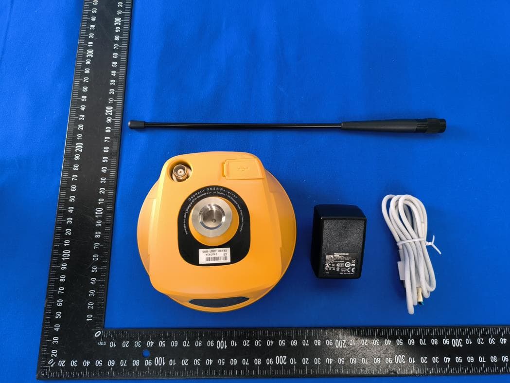
Click to zoom
Application Details
- Equipment Class
- DSS - Part 15 Spread Spectrum Transmitter
- Date of Grant
- Jul 18, 2022
- Application Purpose
- Original Equipment
- Date of Application
- Jul 18, 2022
- Equipment Note
- Geodetic GNSS Receiver
- Frequency Range
- 2402.00000000 - 2480.00000000
- Country
- China
Documents & Files
Document Text
Text extracted from the exhibit documents filed with the FCC. Open a document above to read the original.
Users Manual
By surveyors, for surveyors EFIX C5 GNSS USER GUIDE Survey & Engineering | March 2022 Table of Content EFIX C5 GNSS USER GUIDE | 2022-03 Pa ge | 2 Table of Content Table of Content ............................................................................................................... 2 Preface ............................................................................................................................ 5 Copyright ........................................................................................................................... 5 Safety Warnings ................................................................................................................. 5 1 Introduction .............................................................................................................. 6 1.1 Safety Information ....................................................................................................... 6 1.1.1 Warnings and Cautions ..................................................................................... 6 1.2 Regulations and Safety ................................................................................................ 6 1.2.1 Use and Care ..................................................................................................... 7 1.3 Technical Support ........................................................................................................ 7 1.4 Disclaimer .................................................................................................................... 7 1.5 Your Comments ........................................................................................................... 7 2 Getting Started with C5 ............................................................................................. 8 2.1 About the Receiver ...................................................................................................... 8 2.2 Parts of the Receiver .................................................................................................... 8 2.2.1 Front Panel ........................................................................................................ 8 2.2.2 Receiver Ports ................................................................................................. 10 2.3 Batteries and Power .................................................................................................. 11 2.3.1 Built-in batteries ............................................................................................. 11 2.3.2 Charging the Battery ....................................................................................... 11 2.3.3 Battery Safe .................................................................................................... 11 2.3.4 External Power Supply .................................................................................... 12 2.4 Product Basic Supply Accessories .............................................................................. 13 2.4.1 Base Kit Basic Supply ...................................................................................... 13 2.4.2 Rover Kit Basic Supply ..................................................................................... 14 2.5 Connecting to an Office Computer ............................................................................ 15 2.6 Connecting to a Controller ........................................................................................ 16 2.6.1 Connecting via Wi-Fi with eField Software ..................................................... 16 2.6.2 Connecting via Bluetooth with eField Software ............................................. 17 2.7 Downloading Logged Data ......................................................................................... 19 2.7.1 FTP Download ................................................................................................. 19 2.7.2 Web Server Download .................................................................................... 22 2.7.3 USB Download ................................................................................................ 22 3 Equipment Setup and Operation .............................................................................. 24 Table of Content EFIX C5 GNSS USER GUIDE | 2022-03 Pa ge | 3 3.1 Post-processing Base Station Setup ........................................................................... 24 3.2 Real-Time Base Station Setup .................................................................................... 26 3.3 Real-Time Rover Station Setup .................................................................................. 27 3.4 Working with the Tilt Compensation ......................................................................... 28 3.4.1 Operation Steps .............................................................................................. 28 3.4.2 Notes of using tilt measurement .................................................................... 30 4 Configuring Through a Web Browser ........................................................................ 32 5.1 Status Menu ............................................................................................................... 33 5.1.1 Position Submenu ........................................................................................... 33 5.1.2 Activity Submenu ............................................................................................ 34 5.1.3 Google Map Submenu .................................................................................... 34 5.2 Satellites Menu .......................................................................................................... 35 5.2.1 Tracking Table Submenu ................................................................................. 35 5.2.2 Tracking Info. Table Submenu ...............................…
Text truncated - open the document above for the full version.
Cover Letter(s)
Shanghai EFIX Geomatics Co., Ltd July 11, 2022 Nemko Canada Inc 303 River Road Ottawa, Ontario, Canada K1V 1H2 Attn: Director of Certification Authority to Act as Agent On our behalf, I appoint Shenzhen Alpha Product Testing Co., Ltd. Address: Building i, No.2, Lixin Road, Fuyong Street, Bao’an District, 518103, Shenzhen, Guangdong, China Person: Mark Zhu (Name and address,person). to act as our agent in the preparation of this application for equipment certification. I certify that submitted documents properly describe the device or system for which equipment certification is sought. I also certify that each unit manufactured, imported or marketed, as defined in the Federal Communications Commission’s regulations will have affixed to it a label identical to that submitted for approval with this application. For instances where our authorized agent signs the application for certification on our behalf, I acknowledge that all responsibility for complying with the terms and conditions for certification, as specified by Nemko Canada Inc, still resides with Shanghai EFIX Geomatics Co., Ltd Address: Building 1, 158 Shuanglian Road, Qingpu District, Shanghai ( applicant name and address). Signature: 2022-07-11 Name Glenn Chu Position Certification Manager Company Name Shanghai EFIX Geomatics Co., Ltd Address Building 1, 158 Shuanglian Road, Qingpu District, Shanghai Tel +8675529766001 Email [email protected]
Cover Letter(s)
Shanghai EFIX Geomatics Co., Ltd Office of Engineering Technology Federal Communications Commission 7435 Oakland Mills Road Columbia, MD 21046 Date: 2022-07-11 Subject; Request for Long Term Confidentiality FCC ID: 2A3MU-C5 To Whom It May Concern, Pursuant to the provisions of the Commission’s rules Title 47 Sections §0.457 and §0.459, we are requesting the Commission to withhold the following attachment(s) as confidential documents from public disclosure indefinitely. These documents contain detailed system and equipment descriptions and are considered as proprietary information in operation of the equipment. The public disclosure of these documents might be harmful to our company and would give competitors an unfair advantage in the market. Schematic Diagram Block Diagram Operational Description Turn-up PCB Layout BOM It is our understanding that all measurement test reports, FCC ID label format and correspondence during the certification review process cannot be granted as confidential documents and this information will be available for public review once the grant of equipment authorization is issued. Sincerely, Signature: 2022-07-11 Name Glenn Chu Position Certification Manager Company Name Shanghai EFIX Geomatics Co., Ltd Address Building 1, 158 Shuanglian Road, Qingpu District, Shanghai Tel +8675529766001 Email [email protected]
External Photos
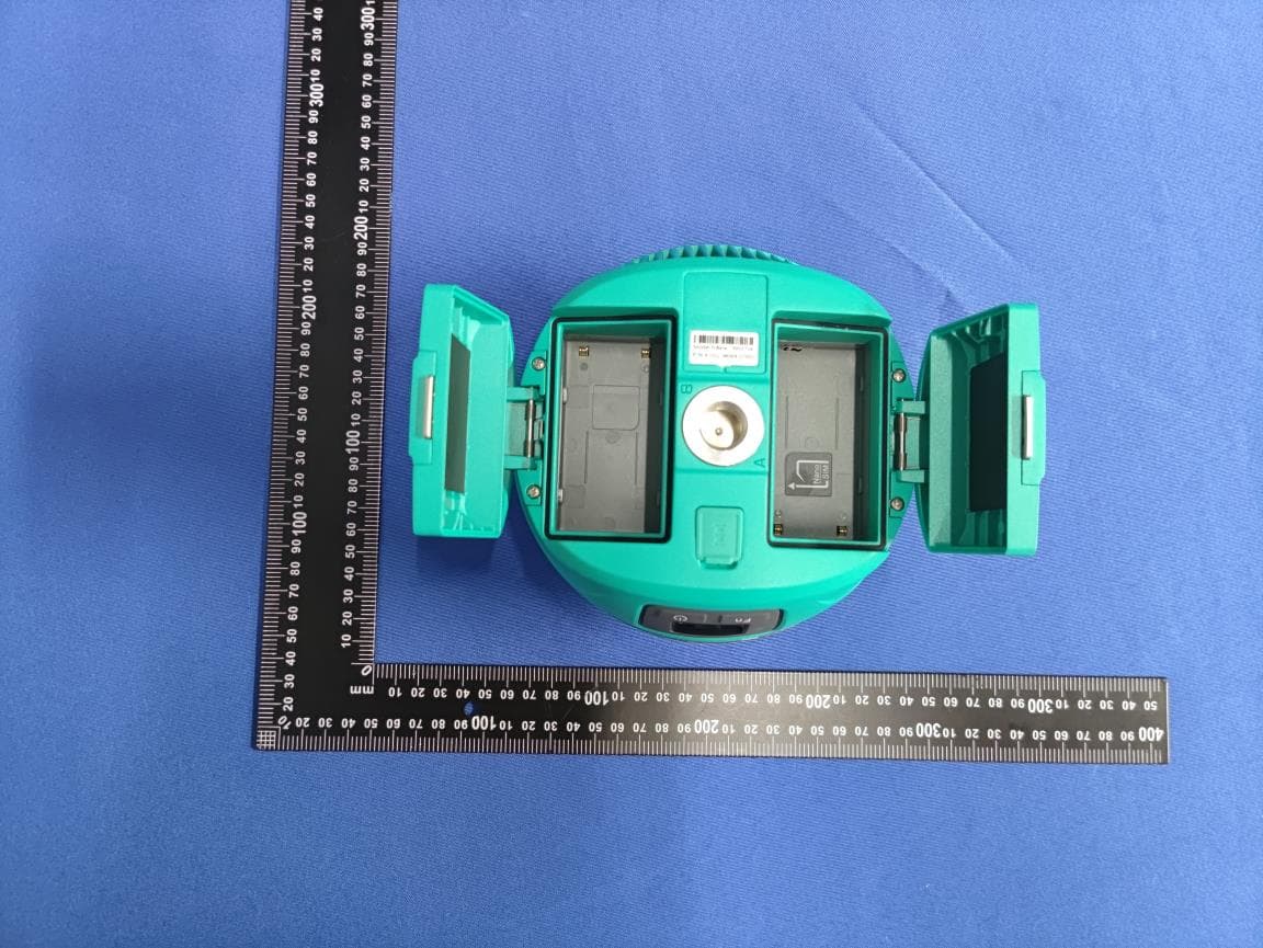
FCC ID: 2A3MU-C5 UHF Receiver ANT FCC ID: 2A3MU-C5 FCC ID: 2A3MU-C5 FCC ID: 2A3MU-C5
ID Label/Location Info
2.5cm 1cm Label Location FCC ID: 2A3MU-C5 Model name: Geodetic GNSS Receiver Model No.: C5
Internal Photos
FCC ID: 2A3MU-C5 FCC ID: 2A3MU-C5 FCC ID: 2A3MU-C5 BT/WiFi ANT FCC ID: 2A3MU-C5 FCC ID: 2A3MU-C5 FCC ID: 2A3MU-C5 FCC ID: 2A3MU-C5
RF Exposure Info
FCC ID: 2A3MU-C5 Prediction of MPE at a given distance According to 447498 D04 Interim General RF Exposure Guidance v01 The MPE-based test exemption condition is in terms of ERP, defined as the product of the maximum antenna gain and the delivered maximum time-averaged power. For this case, a RF source is an RF exempt device if its ERP (watts) is no more than a frequency-dependent value, as detailed tabular form as below. These limits have been derived based on the basic specifications on Maximum Permissible Exposure (MPE) considered for the FCC rules in § 1.1310(e)(1). “f” is in MHz Simultaneous Transmission with MPE-based Exemptions For these cases, a device with multiple RF sources transmitting simultaneously will be considered an RF exempt device if the condition of following Formula is satisfied. As this equipment: Distance=60cm BLE:f1 = 2440, WIFI:f2 = 2437, UHF:f3= 469.95 So P th1 = P th2 =6912.0mW, P th3 = 2165.5mW Where: EIRP = Pm + Gi Pt=10 (EIRP/10) =10 (EIRP-2.15/10) Pm = measured transmitter output power in dBm, Pt = transmitter output power in milliwatts, Gi = numeric gain of the transmitting antenna (unit-dBi) FCC ID: 2A3MU-C5 Ant gain Gi1=1.56 dBi, Gi2=1.56 dBi, Gi3=4 dBi Pm1=4.09 dBm, Pm2=21.58 dBm, Pm3=29.883 dBm So BLE: Pt1=10 (5.65/10) mW =3.673 mW<6912.0mW WIFI: Pt2=10 (23.14/10) mW =206.063 mW<6912.0mW UHF: Pt3=10 (33.883-2.15/10) mW =1490.390 mW<2165.5mW Σ= Pt1/P th1 + Pt2/ P th2 + Pt3/ P th3 =0.72<1 The MPE-based test exemption condition is meets the requirements.
Test Report
ALPHA's reports is using a digital certificate that is trusted on Adobe's official server. If there is no digital certificate or the digital certificate shows damaged in your report. Please do not accept the report. FCC TEST REPORT FCC ID: 2A3MU-C5 On Behalf of Shanghai EFIX Geomatics Co.,Ltd Geodetic GNSS Receiver Model No.: C5 Prepared for : Shanghai EFIX Geomatics Co.,Ltd Address : Building 1, 158 Shuanglian Road, Qingpu District, Shanghai Prepared By : Shenzhen Alpha Product Testing Co., Ltd. Address : Building i, No.2, Lixin Road, Fuyong Street, Bao’an District, 518103, Shenzhen, Guangdong, China Report Number : A2206032-C02-R03 Date of Receipt : June 6, 2022 Date of Test : June 6, 2022 - June 27, 2022 Date of Report : June 29, 2022 Version Number : V0 Page 2 of 70 Report No.: A2206032-C02-R03 TABLE OF CONTENTS Description Page 1. Summary Of Standards And Results ................................................................. 6 1.1. Description of Standards and Results ............................................................ 6 2. General Information ............................................................................................ 7 2.1. Description of Device (EUT) .......................................................................... 7 2.2. Accessories of Device (EUT) ......................................................................... 8 2.3. Tested Supporting System Details ................................................................. 8 2.4. Block Diagram of connection between EUT and simulators .......................... 8 2.5. Test Mode Description ................................................................................... 8 2.6. Test Conditions .............................................................................................. 9 2.7. Test Facility .................................................................................................... 9 2.8. Measurement Uncertainty .............................................................................. 9 2.9. Test Equipment List ...................................................................................... 10 3. Maximum Peak Output Power .......................................................................... 11 3.1. Limit ............................................................................................................. 11 3.2. Test Procedure ............................................................................................. 11 3.3. Test Setup .................................................................................................... 11 3.4. Test Result ................................................................................................... 11 4. Bandwidth .......................................................................................................... 12 4.1. Limit ............................................................................................................. 12 4.2. Test Procedure ............................................................................................. 12 4.3. Test Result ................................................................................................... 12 5. Carrier Frequency Separation .......................................................................... 22 5.1. Limit ............................................................................................................. 22 5.2. Test Procedure ............................................................................................. 22 5.3. Test Result ................................................................................................... 22 6. Number Of Hopping Channel ........................................................................... 24 6.1. Limit ............................................................................................................. 24 6.2. Test Procedure ............................................................................................. 24 6.3. Test Result ................................................................................................... 24 7. Dwell Time .......................................................................................................... 26 7.1. Test limit ....................................................................................................... 26 7.2. Test Procedure ............................................................................................. 26 7.3. Test Result ................................................................................................... 26 8. Radiated Emissions .......................................................................................... 43 8.1. Limit ............................................................................................................. 43 8.2. Block Diagram of Test setup ........................................................................ 44 8.3. Test Procedure ............................................................................................. 45 8.4. Test Result ................................................................................................... 45 9. Band Edge Compliance .................................................................................... 56 Page 3 of 70 Report No.: A2206032-C02-R03 9.1. Block Diagram of Test Setup ........................................................................ 56 9.2. Limit ............................................................................................................. 56 9.3. Test Procedure ............................................................................................. 56 9.4. Test Result ................................................................................................... 56 10. Power Line Conducted Emissions ................................................................... 66 10.1. Block Diagram of T…
Text truncated - open the document above for the full version.
Test Setup Photos
FCC ID: 2A3MU-C5 Photos of Radiated Emission Test (In Semi Anechoic Chamber 30MHz~1GHz) Photos of Radiated Emission Test (In Semi Anechoic Chamber above 1GHz) FCC ID: 2A3MU-C5 Photos of Conducted disturbance at mains terminals test
Contact Information
Applicant
Glenn Chu(Certificate manager)
Test Firm
Shenzhen Alpha Product Testing Co., LTD.Real Yak
[email protected]+86 755 29766001
Technical Specifications
| # | Rule Parts | Frequency Range | Power Output |
|---|---|---|---|
| 1 | 15C | 2.40 GHz - 2.48 GHz | 2.50 mW |
Other Applications from Shanghai EFIX Geomatics Co., Ltd
2A3MU-NBASE
Jul 13, 2026Geodetic GNSS Receiver
Equipment Class
TNB - Licensed Non-Broadcast Station Transmitter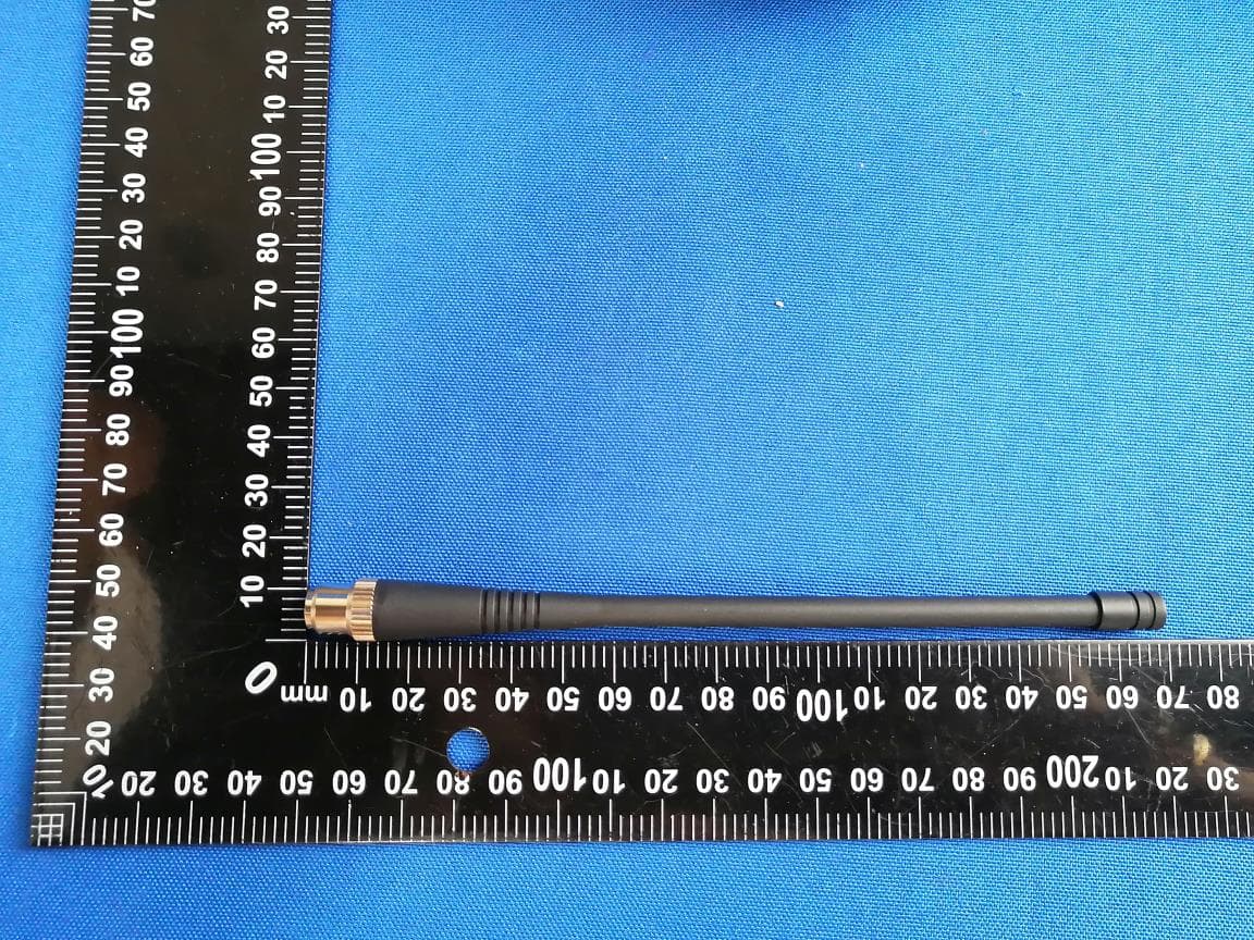
2A3MU-N50
May 13, 2026Geodetic GNSS Receiver
Equipment Class
TNB - Licensed Non-Broadcast Station Transmitter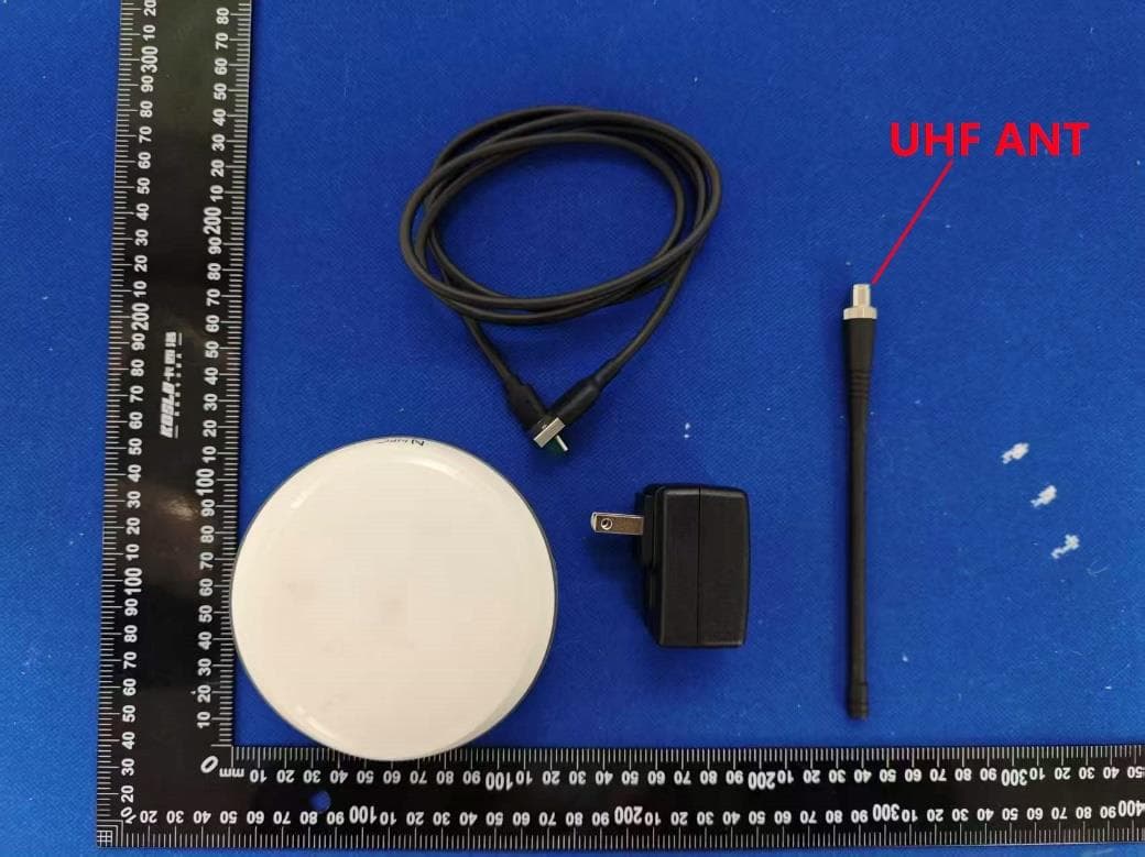
2A3MU-N30
Apr 30, 2026Geodetic GNSS Receiver
Equipment Class
DXX - Part 15 Low Power Communication Device Transmitter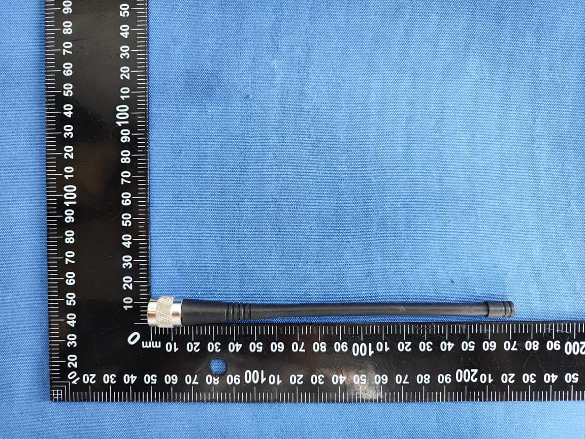
2A3MU-F8
Sep 29, 2025Geodetic GNSS Receiver
Equipment Class
DSS - Part 15 Spread Spectrum Transmitter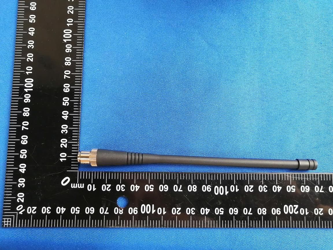
2A3MU-F8L
Sep 11, 2025Geodetic GNSS Receiver
Equipment Class
DSS - Part 15 Spread Spectrum Transmitter