2A3OF-NV008SNight Vision
Shenzhen Pard Technology Co.,Ltd
Click to zoom
Application Details
- Equipment Class
- DTS - Digital Transmission System
- Date of Grant
- Jan 09, 2022
- Application Purpose
- Original Equipment
- Date of Application
- Jan 09, 2022
- Equipment Note
- Night Vision
- Frequency Range
- 2412.00000000 - 2462.00000000
- Country
- China
Documents & Files
Document Text
Text extracted from the exhibit documents filed with the FCC. Open a document above to read the original.
Users Manual
Digital Night Vision PARD NV008S —1— Standard Version —2— Rangefinder Version Notes —3— 1.Don't look at the IR infrared light directly, or it will damage your eyes! 2.Massive power will be gathered when the infrared light is turned on. D aim at flammable items at a close range, otherwise it may cause fire. Please turn the infrared light off or enter sleep mode after use. on't 3. Please use a rechargeable battery with a rated voltage of 3.7V! 4. Attempts to disassemble or repair the device without authorization will void the warranty. Please contact with the maintenance point in time if there's any needs. PARD Digital Night Vision NV008S —4— —5— Package Contents This box contains a night vision optics with, Installation 1.Battery installation —6— 1*NV008P/NV008P-LRF; 1* Micro USB cable; 2*Hex-nut wrenches ;1* Mount Storage card is not included. Please prepare a TF card (128g maximum) for data storage. Please use lithium chargeable 3.7V flat battery 18650. Remove battery compartment cap and make sure setting the positive polar towards to the direction inward. Put the cap back and screw it until tight. ( Fail to do so may result in restarting!). 3. Mount Installation 2.Adjustments —7— A simple test can be taken to check the functions of the device after the installation of battery. First, rotate and adjust the eyepiece dioptre adjustment ring(6) until you see the four-character icon on the screen ( there's no need to see a clear image ), then rotate the Objective lens adjustment ring(7) until you can see your target clearly. Second, switch to different modes, test IR, Red dot or Rangefinder. There's three mounting holes in the base of the device. Attach the mount to the base of the device by using a hex-nut wrench and screws. The mount can be installed in multiple rails. Specifications Model Magnifying power IR power IR wave length IR illuminate distance Video resolution Eyepiece resolution Ballistic Ranging range Protection Dimension NV008S 6.5x-13x 5w 850nm Ip67 1920*1080 >8h Battery life Diopter ±5 Focusing 1024*768 350m 137*51*65.5 Color mode Color/ Mono Transmission method WiFi 30mm Yes 3cm-∞ NV008S-LRF Eye Relief 1200m / Instructions 1.Turn On/Off: 2.Sleep Mode: 3The Eyepiece Dioptre Adjustment. Turn on the device with a short press of Power button(12).Turn off the device with a long press of Power button(12). Power indicator(3) will keep light when the device is turned on. Enter sleep mode with a short press of Power/Sleep button(12) when the device is turned on. Power indicator(3) will keep light when the device entering sleep mode. The purpose of dioptre adjustment is to get a clear image for users with different vision. Rotate and adjust the di o ptre adj u s t m e n t ring (6) unti (mm) Calculator Transmission por t Type C Adjustment —8— —9— 5.IR Fill Light Control Turn on the device, enter black and white mode with a long press of IR button(10). Switch to IR1-3 or off with a short press of IR button. The part of fill light(1) is stretchable which can be pull out or push back to make an quick adjustment. 4.The Objective Lens Adjustment you get a clear view of the four-character icon on the screen. One adjustment only for each eye. (Please note it's possible that the image is not clear without the adjustment of objective lens.) Make sure the eyepiece dioptre adjustment is finished. Aiming at your target, rotate and adjust the objective lens ring(7) until you get a clear and well-focused image. —10— 6.Red dot Adjustment 7.Menu operation Turn on the device, then turn the laser on/off with a short press of Laser/Menu button(11). The position of laser can be adjusted on the laser adjustment holes(2) by a hex-nut wrench. Enter the menu with a long press of Menu button(11). Press +/- button (8/10) to select options. Enter a submenu with a short press of OK button (9). Exit the menu with a short press of Menu button(11). —11— Warranty card Product model: Product code: Date of purchase: Warranty period: User Name: User's phone: User address: Warranty records: REMARK : PARD has an original mount included in the NV008P/NV008P-LRF standard package. In order to have the best usage experience, we highly recommended user make use of PARD original mount when apply the device to your rifles. If users want to use their own mount, there may have some variance when zeroing the machine. This is a normal phenomenon. PARD provided 2 pieces of small metal plates in the product package, for users put at the rail to adjust the horizontal level when mounting NV008P/LRF on. PLEASE CONSULT OUR ONLINE CUSTOMER SERVICE IF YOUR HAVE ANY PROBLEM WHEN MOUNTING OUR DEVICES AT YOUR ORIGINAL RIFLE RAIL. Warranty Telephone:+86-0755-29484438 Website:www.pard-tech.com Address:No. 328 Baoshi East Road, Shiyan, Bao`an District, Shenzhen, China T h i s p r o d u c t i s w a r r a n t e d a g a i n s t d e f e c t s i n m a t e r i a l s a n d workmanship for a period of one year from the date of purchase. Warning: Changes or modifications to this unit not expressly approved by the party responsible for compliance could void the user’s authority to operate the equipment. NOTE: This device complies with part 15 of the FCC Rules. Operation is subject to the following two conditions: (1) This device may not cause harmful interference, and (2) this device must accept any interference received, including interference that may cause undesired operation. —13— This warranty is for the original purchaser only! Notice: Do not disassemble the night vision device by yourself. If there is any trouble,please contact the factory in time. If the repair, modification or product seal sticker is not approved by the company, it will not be covered by the warranty. All damage caused by human factors or accidental product damage, including use in abnormal working conditions, damage caused by failure to follow the instructions and installation, is not covered by the warranty. —12— FCC Statement: This equipment has been tested and found to comply…
Text truncated - open the document above for the full version.
Cover Letter(s)
Shenzhen Pard Technology Co.,Ltd Agent Authorization Company: Shenzhen Pard Technology Co.,Ltd Address: B78,18/F,Guangyin building,38 Futian South Road, port community, Futian street, Futian District, Shenzhen Product Name: Night Vision Model Number(s): NV008S, NV008S-850, NV008S-940, NV008X, NV008X-850, NV008X-940, NV008T, NV008T-850, NV008T-940, NV008S-LRF, NV008S-LRF-850, NV008S-LRF-940, NV008X-LRF, NV008X-LRF-850, NV008X-LRF-940, NV008T- LRF, NV008T-LRF-850, NV008T-LRF-940, SA-PLUS, SA32, SA37, SA62, SA- PLUS-LRF, SA32-LRF, SA37-LRF, SA62-LRF We authorize MiCOM Labs Inc., 575 Boulder Court, Pleasanton, California 94566, USA, to act on our behalf on all matters concerning the certification of above named equipment. We declare that MiCOM Labs Inc. is allowed to forward all information related to the approval and certification of equipment to the regulatory agencies as required and to discuss any issues concerning the approval application. Any and all acts carried out by MiCOM Labs on our behalf shall have the same effect as acts of our own. Date: Nov. 29, 2021Signature: Name:Anna Ai Title: manager Company: Shenzhen Pard Technology Co.,Ltd
Cover Letter(s)
Shenzhen Pard Technology Co.,Ltd Date: Nov. 29, 2021 Office of Engineering Technology Federal Communications Commission 7435 Oakland Mills Road Columbia, MD 21046 USA Subject; Request for Confidentiality FCC ID: 2A3OF-NV008S To Whom It May Concern, Pursuant to the provisions of the Commission’s rules Title 47 Sections §0.457 and §0.459, we are requesting the Commission to withhold the following attachment(s) as confidential documents from public disclosure indefinitely. These documents contain detailed system and equipment descriptions and are considered as proprietary information in operation of the equipment. The public disclosure of these documents might be harmful to our company and would give competitors an unfair advantage in the market. Schematic Diagram Block Diagram Parts List Operational Description Tune-up Procedure In additional to above mentioned documents, in order to comply with the marketing regulations in Title 47 CFR §2.803 and the importation rules in Title 47 CFR §2.1204, while ensuring that business sensitive information remains confidential until the actual marketing of newly authorized devices, we request Short Term Confidentiality of the following attachment(s); External Photos Test Setup Photos Internal Photos User Manual For 45 days, pursuant to Public Notice DA 04-1705. OR For 180 days pursuant to KDB 726920 D01. It is our understanding that all measurement test reports, FCC ID label format and correspondence during the certification review process cannot be granted as confidential documents and this information will be available for public review once the grant of equipment authorization is issued. Sincerely, Signature: Name: Anna Ai Title: manager
ID Label/Location Info
Label location Label size:10*60mm Label sample: Night Vision MODEL: NV008S FCC ID:2A3OF-NV008S MADE IN CHINA
Internal Photos
BATTERY ANT
RF Exposure Info
FCC ID: 2A3OF-NV008S RF Exposure Evaluation According to KDB 447498 and part 2.1093,Unless specifically required by the published RF exposure KDB procedures, standalone 1-g head or body and 10-g extremity SAR evaluation for general population exposure conditions, by measurement or numerical simulation, is not required when the corresponding SAR Test Exclusion Threshold condition(s), listed below, is (are) satisfied. For 100 MHz to 6 GHz and test separation distances ≤ 5.0 mm, the 1-g and 10-g SAR test exclusion thresholds are determined by the following: [(max. power of channel, including tune-up tolerance, mW) / (min . test separation distance, mm)] · [√f (GHz) ] ≤ 3.0 for 1-g SAR, and ≤ 7.5 for 10-g extremity SAR, where f (GHz) is the RF channel transmit frequency in GHz Power and distance are rounded to the nearest mW and mm before calculation The result is rounded to one decimal place for comparison Here, 2.4GWIFI-worst mode and channel Frequency (MHz) Max Power (dBm) Tune up tolerance (dBm) Maximum tune-up (dBm) (mW) 802.11b 2462MHz 8.94 8±1 9 7.943 Max tune-up Power (dBm) Max tune-up Power (mW) Frequency (MHz) Min. distance (mm) Calc. thresholds limit 9 7.943 2462 5 2.493 3.0 Calculated value-2.493< 3.0, So there is no require SAR test
Test Report
Project No.:ZKT-211228L7327 Page 1 of 68 FCC TEST REPORT FCC ID:2A3OF-NV008S Report Number. .............................. : ZKT-211228L7327 Date of Test ........................................ Dec. 21, 2021 -- Dec. 31, 2021 Date of issue ..................................... : Dec. 31, 2021 Total number of pages ....................... 68 Test Result ........................................ : PASS Testing Laboratory. ........................ : Shenzhen ZKT Technology Co., Ltd. Address ........................................... : 1/F, No. 101, Building B, No. 6, Tangwei Community Industrial Avenue, Fuhai Street, Bao'an District, Shenzhen, China Applicant's name .......................... : Shenzhen Pard Technology Co., Ltd Address ........................................... : B78, 18/F, Guangyin building, 38 Futian South Road, port community, Futian street, Futian District, Shenzhen Manufacturer's name .................... : Shenzhen Pard Technology Co., Ltd Address ........................................... : B78, 18/F, Guangyin building, 38 Futian South Road, port community, Futian street, Futian District, Shenzhen Test specification: Standard ........................................... : FCC CFR Title 47 Part 15 Subpart C Section 15.247 ANSI C63.10:2013 KDB558074 D0115.247 Meas Guidance v 05r02 Test procedure ................................. : / Test Report Form No. ..................... : TRF-EL-110_V0 Test Report Form(s) Originator ..... : ZKT Testing Master TRF .................................... : Dated: 2020-01-06 This device described above has been tested by ZKT, and the test results show that the equipment under test (EUT) is in compliance with the FCC requirements. And it is applicable only to the tested sample identified in the report. This report shall not be reproduced except in full, without the written approval of ZKT, this document may be altered or revised by ZKT, personal only, and shall be noted in the revision of the document. Product name.................................. : Night Vision Trademark ...................................... : PARD Project No.:ZKT-211228L7327 Page 2 of 68 Testing procedure and testing location: Testing Laboratory .................................. : Shenzhen ZKT Technology Co., Ltd. Address...................................................... : 1/F, No. 101, Building B, No. 6, Tangwei Community Industrial Avenue, Fuhai Street, Bao'an District, Shenzhen, China Alen He Tested by (name + signature) .................... : Joe Liu Reviewer (name + signature) .................... : Lake Xie Approved (name + signature) .................... : Model/Type reference ....................... : NV008S, NV008S-850, NV008S-940, NV008X, NV008X-850, NV008X-940, NV008T, NV008T-850, NV008T-940, NV008S-LRF, NV008S-LRF-850, NV008S-LRF-940, NV008X-LRF, NV008X-LRF-850, NV008X-LRF-940, NV008T-LRF, NV008T-LRF-850, NV008T-LRF-940, SA-PLUS, SA32, SA37, SA62, SA-PLUS-LRF, SA32-LRF, SA37-LRF, SA62-LRF Ratings ............................................. : DC 3.7V from battery DC 5V 1A from adapter or others Project No.:ZKT-211228L7327 Page 3 of 68 Table of Contents Page 1. VERSION 5 2. SUMMARY OF TEST RESULTS 6 2.1 TEST FACILITY 6 2.2 MEASUREMENT UNCERTAINTY 7 3. GENERAL INFORMATION 7 3.1 GENERAL DESCRIPTION OF EUT 7 3.2 DESCRIPTION OF TEST MODES 9 3.3 BLOCK DIGRAM SHOWING THE CONFIGURATION OF SYSTEM TESTED 9 3.4 DESCRIPTION OF SUPPORT UNITS(CONDUCTED MODE) 10 3.5EQUIPMENTS LIST FOR ALL TEST ITEMS 11 4. EMC EMISSION TEST 12 4.1 CONDUCTED EMISSION MEASUREMENT 12 4.1.1 POWER LINE CONDUCTED EMISSION LIMITS 12 4.1.2 TEST PROCEDURE 12 4.1.3 DEVIATION FROM TEST STANDARD 12 4.1.4 TEST SETUP 13 4.1.5 EUT OPERATING CONDITIONS 13 4.1.6 TEST RESULT 14 4.2 RADIATED EMISSION MEASUREMENT 16 4.2.1 RADIATED EMISSION LIMITS 16 4.2.2 TEST PROCEDURE 17 4.2.3 DEVIATION FROM TEST STANDARD 17 4.2.4 TEST SETUP 18 4.2.5 EUT OPERATING CONDITIONS 19 4.2.6 TEST RESULTS 20 5.RADIATED BAND EMISSIONMEASUREMENT 30 5.1 TEST REQUIREMENT: 30 5.2 TEST PROCEDURE 30 5.3 DEVIATION FROM TEST STANDARD 31 5.4 TEST SETUP 31 5.5 EUT OPERATING CONDITIONS 31 5.6 TEST RESULT 32 6.POWER SPECTRAL DENSITY TEST 35 6.1 APPLIED PROCEDURES / LIMIT 35 Project No.:ZKT-211228L7327 Page 4 of 68 6.2 TEST PROCEDURE 35 6.3 DEVIATION FROM STANDARD 35 6.4 TEST SETUP 35 6.5 EUT OPERATION CONDITIONS 35 6.6 TEST RESULT 36 7. CHANNEL BANDWIDTH 44 7.1 APPLIED PROCEDURES / LIMIT 44 7.2 TEST PROCEDURE 44 7.3 DEVIATION FROM STANDARD 44 7.4 TEST SETUP 44 7.5 EUT OPERATION CONDITIONS 44 7.6 TEST RESULT 45 8.OUTPUT POWER TEST 48 8.1 APPLIED PROCEDURES/LIMIT 48 8.2 TEST PROCEDURE 48 8.3 DEVIATION FROM STANDARD 48 8.4 TEST SETUP 48 8.5 EUT OPERATION CONDITIONS 48 8.6 TEST RESULT 49 9. CONDUCTED BAND EDGE AND SPURIOUS EMISSION 50 9.1 APPLICABLE STANDARD 50 9.2 TEST PROCEDURE 50 9.3 DEVIATION FROM STANDARD 50 9.4 TEST SETUP 50 9.5 EUT OPERATION CONDITIONS 50 9.6 TEST RESULTS 50 10. ANTENNA REQUIREMENT 65 11. TEST SETUP PHOTO 66 12. EUT CONSTRUCTIONAL DETAILS 68 Project No.:ZKT-211228L7327 Page 5 of 68 1. VERSION ReportNo. Version Description Approved ZKT-211228L7327 Rev.01 Initial issue of report Dec. 30, 2021 Project No.:ZKT-211228L7327 Page 6 of 68 2. SUMMARY OF TEST RESULTS Test procedures according to the technical standards: FCC Part15 (15.247) , Subpart C Standard Section Test Item Result Remark FCC part 15.203/15.247 (c) Antenna requirement PASS FCC part 15.207 AC Power Line Conducted Emission PASS FCC part 15.247 (b)(3) Conducted Peak Output Power PASS FCC part 15.247 (a)(2) Channel Bandwidth& 99% OCB PASS FCC part 15.247 (e) Power Spectral Density PASS FCC part 15.247(d) Band Edge PASS FCC part 15.205/15.209 Spurious Emission PASS NOTE: (1)” N/A” denotes test is not applicable in this Test Report 2.1 TEST FACILITY Shenzhen ZKT Technology Co., Ltd. Add. : 1/F, No. 101, Building B, No. 6, Tangwei Community Industrial Avenue, Fuhai Street, Bao'an District, Shenzhen, China FCC Test Firm Registration Number: 692225 Designation Numbe…
Text truncated - open the document above for the full version.
Contact Information
Applicant
Anna Ai
Technical Contact
Test Firm
Shenzhen ZKT Technology Co., Ltd.Lake Xie
[email protected]0086-13620010775
Technical Specifications
| # | Rule Parts | Frequency Range | Power Output |
|---|---|---|---|
| 1 | 15C | 2.41 GHz - 2.46 GHz | 7.83 mW |
Other Applications from Shenzhen Pard Technology Co.,Ltd
2A3OF-OSPREY4K
May 20, 2026Multi- spectral Digital Camera
Equipment Class
DTS - Digital Transmission System
2A3OF-CRUX256
May 07, 2026Thermal Imaging Camera
Equipment Class
DTS - Digital Transmission System
2A3OF-BS1
Dec 04, 2025Thermal Imaging Camera
Equipment Class
DTS - Digital Transmission System
2A3OF-BT56
Dec 04, 2025Thermal Imaging Camera
Equipment Class
DTS - Digital Transmission System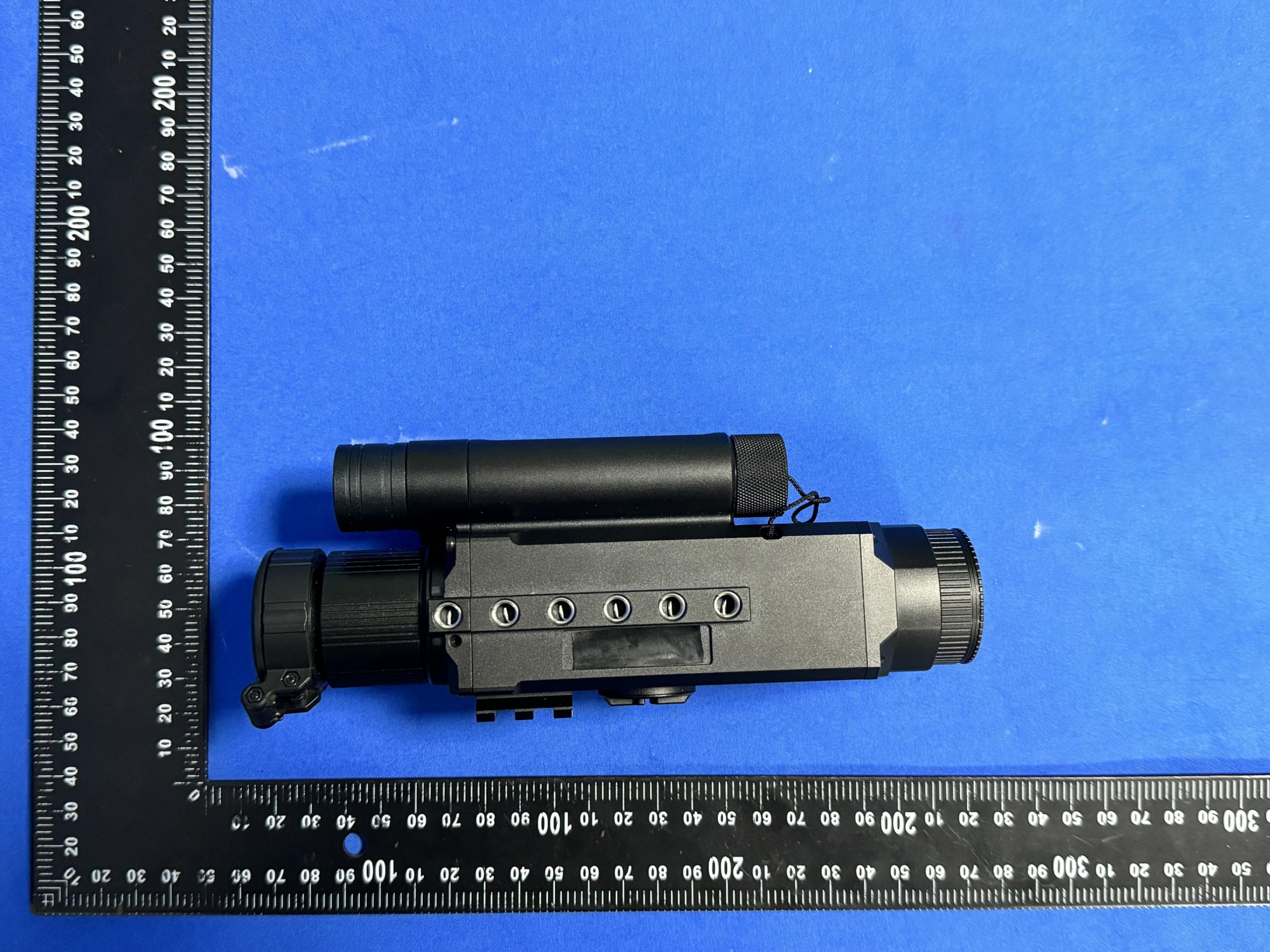
2A3OFNIGHTWARRIOR4K
Jun 03, 2024Digital Night Vision Camera
Equipment Class
DTS - Digital Transmission System