2A4G5-HLM5934SX1302 Gateway Module
Hangzhou Hylin IoT Technology Co., Ltd.
Click to zoom
Application Details
- Equipment Class
- DTS - Digital Transmission System
- Date of Grant
- Jul 14, 2022
- Application Purpose
- Original Equipment
- Date of Application
- Jul 14, 2022
- Equipment Note
- SX1302 Gateway Module
- Frequency Range
- 923.30000000 - 927.50000000
- Country
- China
Documents & Files
Document Text
Text extracted from the exhibit documents filed with the FCC. Open a document above to read the original.
Users Manual
C o n n e c t i v i t y f o r I n n o v a t i o n V1.3 Date:2022/01/061 )-.Y83Y Y93Y Y85Y Y95Y HLMx83x,x93x,x85x,x95x Series User manual Hylintech Corporation C o n n e c t i v i t y f o r I n n o v a t i o n V1.3 Date:2022/01/062 )-.Y83Y Y93Y Y85Y Y95Y Revisions VersionDateAuthorDescription 1.02021-06-18HylintechInitial Version 1.012021-07-13HylintechModify interface 1.112021-09-08HylintechModify interface 1.22021-10-24HylintechModify interface 1.212021-11-03HylintechAdd reset Pin description 1.222021-11-16HylintechHLM9931 EOL 1.32022-01-06HylintechAdding new models Copyright ©HylinTech Co.,Ltd C o n n e c t i v i t y f o r I n n o v a t i o n V1.3 Date:2022/01/063 )-.Y83Y Y93Y Y85Y Y95Y Contents 1.Overview........................................................................................................5 2.Specification..................................................................................................6 3.Package.and.Pin.Connections......................................................................7 3.1.Package....................................................................................................................7 3.2.Pin.Connections......................................................................................................8 4. Basic.Usage..................................................................................................10 4.1.Application.Circuit................................................................................................10 4.2.Layout....................................................................................................................11 4.3.SPI.Timings............................................................................................................12 C o n n e c t i v i t y f o r I n n o v a t i o n V1.3 Date:2022/01/064 )-.Y83Y Y93Y Y85Y Y95Y Picture Index Pic.1-1.Module.rendering.image..................................................................................5 Pic.3-1.Module.Outline.Dimension.Drawing...............................................................8 Pic.4-1.Typical.Application.Circuit.............................................................................11 Pic.4-3.SPI.Timings......................................................................................................12 Table Index Table.1-1..Model.List.....................................................................................................6 Table.2-1.Absolute.Minimum.and.Maximum.Ratings.................................................6 Table.2-2.Electrical.Specifications...............................................................................7 Table.3-1.Pinout............................................................................................................9 V1.0 Date:2022/01/065 )-.Y83Y Y93Y Y85Y Y95Y C o n n e c t i v i t y f o r I n n o v a t i o n 1.Overview HLMx93x series modules are developed based on the digital baseband chip SX1302 with a mechanical definition of the Mini PCIe interface and provide SPI interface. HLMx93x can be applied to LoRaWAN gateways, private LoRa network gateways, and can also be used to develop LoRa network analysis tools. In addition, SX1302 has lower power consumption, higher data throughput, and better cost compared to its predecessor. Key Features • Supports multiple bands •SPI Interface •(G)FSK demodulator •High precision TCXO clock source Typical Specification •operating range from -40 to +85° C •Power supply voltage range: 3.0V-3.6V •Antenna interface: IPEX-1 Usage •LoRa/LoRaWAN Gateway •LoRa Network Analysis Tool C o n n e c t i v i t y f o r I n n o v a t i o n V1.3 Date:2022/01/066 )-.Y83Y Y93Y Y85Y Y95Y Model Information *ModelTx.BandMax.PowerRx.BandLBTMOQ HLM7931490-510MHz22dBm470-510MHzNot Support3000 HLM7932470-510MHz22dBm470-510MHzSupport1000 HLM9931863-928MHz27dBm863-928MHzSupportEOL HLM9932863-928MHz27dBm863-928MHzSupport1000 HLM9933 902-928MHz28dBm902-928MHz Support1000 HLM8934863-870MHz27dBm863-870MHzSupport1000 HLM5934 902-928MHz 27dBm 902-928MHz Support1000 HLM9934TBD27dBmTBDSupport- HLM8834TBD21dBmTBDSupport- HLM5834TBD21dBmTBDSupport- HLM9834TBD21dBmTBDSupport- HLM9953TBD27dBmTBDSupport- *The full model number will contain the "-xxx" suffix to distinguish the packaging method, screen printing information, etc., such as HLM5934-P01. 2.Specifications Table.2-1.Absolute.Minimum.and.Maximum.Ratings Name Value Description MinMaxUnit Power Supply -0.5+3.9 V Storage temperature -40+125 °C Peak reflow temperature -260 °C Table.2-2.Electrical.Specifications Table.1-1..Model.List C o n n e c t i v i t y f o r I n n o v a t i o n V1.3 Date:2022/01/067 )-.Y83Y Y93Y Y85Y Y95Y Name Value Description MinTypMaxUnit Power Supply 3.03.33.6 V The transmitting power decreases when the supply voltage is below 3.0V Operating temperature-40 -85 °C Frequency Stability 2 ppm 25°C Tx Power * HLM7931 202122 dBm @490MHz~510MHz HLM7932202122 dBm @470MHz~510MHz HLM9932252627 dBm @863MHz~928MHz HLM9933 20 24 28 dBm @902MHz~928MHz HLM8934252627 dBm @863MHz~870MHz HLM5934 23 25 27 dBm @902MHz~928MHz HLM9934 dBm TBD HLM8834 dBm TBD HLM5834 dBm TBD HLM9834 dBm TBD HLM9953 dBm TBD Rx Sensitivity** HLM7931 -127 dBm SF7BW125CR4/5@470MHz~510MHz HLM7932-127 dBm SF7BW125CR4/5@470MHz~510MHz HLM9932-127 dBm SF7BW125CR4/5@863MHz~928MHz HLM9933-127 dBm SF7BW125CR4/5@863MHz~928MHz HLM8934-125 dBm SF7BW125CR4/5@863MHz~870MHz HLM5934-126 dBm SF7BW125CR4/5@902MHz~928MHz HLM9934 dBm TBD HLM8834 dBm TBD HLM5834 dBm TBD HLM9834 dBm TBD HLM9953 dBm TBD Interface PackagingMini PCIe Digital InterfaceSPI- Dimension (mm)30×50.95×3 Dimensional accuracyGB/T1804-C * CW.Test.under.nominal.temperature.and.voltage.conditions. **Sensitivity.is.specified.with.a.PER=1%,.32Bytes,.all.under.nominal.temperature.and.voltage.conditions. C o n n e c t i v i t y f o r I n n o v a t i o n V1.3 Date:2022/01/068 )-.Y83Y Y93Y Y85Y Y95Y 3.Package and Pin Connections 3.1.Package Pic.3-1.Module.O…
Text truncated - open the document above for the full version.
Cover Letter(s)
Company Name: Hang zhou Hylin IoT Technology Co.,Ltd. Add: No.80 Pingshui WestRoad xihu District Hangzhou China Tel: 13757198600 Fax: N/A E- mail: [email protected] Modular Approval Letter Date:2022-06-30 FEDERAL COMMUNICATIONS COMMISSIONS Authorization and Evaluation Division 7435 Oakland Mills Road Columbia, MD 21046 We, Hangzhou Hylin IoT Technology Co.,Ltd., hereby request Modular Approval for Product: SX1302 Gateway Module (Model number: HLM5934, HLM5934-H01, GPML9932-PX-V3-US915,DSM-060-US, HLM5934-T01, FCC ID:2A4G5-HLM5934).The EUT meets all of the requirement for modular approval as detailed in FCC 15.212. the requirements is described below: 1. The modular has RF shielding, please refer to the EUT photo. 2. The modular transmitter has buffered modulation/data inputs, Buffered data inputs stage has been integrated in chip (Model:SX1302). 3. The modular transmitter has its own power supply regulation. Please refer to the schematic. 4. Comply with the antenna requirements of Section 15.203 and 15.204(c), the modular has a Monopole antenna which uses a unique type of connector to attach to the EUT, the maximum gain is 2dBi. 5. The EUT was tested in a stand-alone configuration, please refer to setup photos exhibit for details. 6. The module labeled with its own FCC ID. 7. Comply with any specific rules or operating requirements that ordinarily apply to a complete transmitter and the manufacturer must provide adequate instructions along with the module to explain any such requirements. The necessary explanation to be complied with this requirement is contained in the user manual, band please refers to the User Manual. 8. Comply with FCC §15.247 (i) & §1.1310 & §2.1091RF exposure requirements in its final configuration. Sincerely, Signature: Printer Name: Sean Xu Title: CEO
Cover Letter(s)
Company Name: Hangzhou Hylin IoT Technology Co.,Ltd. Add: No.80 Pingshui WestRoad xihu District Hangzhou China Tel: 13757198600 Fax: N/A E- mail: [email protected] FCC Confidential Authorization Date: 2022-06-29 FEDERAL COMMUNICATIONS COMMISSIONS Authorization and Evaluation Division 7435 Oakland Mills Road Columbia, MD 21046 Subject: Confidentiality Request regarding application for certification of FCC ID: 2A4G5-HLM5934 In accordance with Sections 0.457 and 0.459 of the Commission’s Rules, Hangzhou Hylin IoT Technology Co.,Ltd. hereby requests long-term confidential treatment of information accompanying this application as outlined below: •Block Diagram •Schematics •Operation Description The above materials contain proprietary and confidential information not customarily released to the public. The public disclosure of these materials provides unjustified benefits to its competitors in the market. Sincerely, Signature: Printer Name: Sean Xu Title: CEO QA-FR-171-A
Cover Letter(s)
Company Name: Hangzhou Hylin IoT Technology Co.,Ltd. Add: No.80 Pingshui WestRoad xihu District Hangzhou China Tel: 13757198600 Fax: N/A E-mail: [email protected] FCC Authorization Date:2022-06-29 FEDERAL COMMUNICATIONS COMMISSION Authorization and Evaluation Division 7435 Oakland Mills Road Columbia, MD 21046 Subject: Agent Authorization To whom it may concern: We, Hangzhou Hylin IoT Technology Co.,Ltd. Hereby authorizes CHINA CERTIFICATION ICT CO., LTD (DONGGUAN) to act on its behalf in all matters relating to application for Equipment authorization, including the signing of all documents relating to these matters. All acts carried out by CHINA CERTIFICATION ICT CO., LTD (DONGGUAN) on our behalf shall have the same effect as our own action. We, the undersigned, hereby certify that we are not subject to a denial of federal benefits, that includes FCC benefits, pursuant to Section 5301 of the Anti-Drug Abuse Act of 1988, 21 U.S.C. 862. This authorization is valid until further written notice from the applicant. Sincerely Yours, Signature: Printed Name: Sean Xu Title: CEO QA-FR-170-B
Cover Letter(s)
Company Name: Hangzhou Hylin IoT Technology Co.,Ltd. Add: No.80 Pingshui WestRoad xihu District Hangzhou China Tel: 13757198600 Fax: N/A E-mail: [email protected] DECLARATION Date: 2022-06-29 We, Hangzhou Hylin IoT Technology Co.,Ltd. hereby declare that product name:SX1302 Gateway Module (FCC ID:2A4G5-HLM5934 ,model name:HLM5934,HLM5934-H01,GPML9932-PX-V3-US915,DSM-060-US, HLM5934-T01) are electrically identical with the PCB design, components and electromagnetic compatibility characteristics, and model: HLM5934 have been tested by CHINA CERTIFICATION ICT CO., LTD (DONGGUAN). The differences of them are as follows: 1. model name Please contact me if there is need for any additional clarification or information. Sincerely, Sig natur e: Print Name: Sean Xu Title:CEO FEDERAL COMMUNICATIONS COMMISSIONS Authorization and Evaluation Division 74 3 5 Oakland Mills Road Columbia, MD 21046
External Photos
EXHIBIT B - EUT EXTERNAL PHOTOGRAPHS
Internal Photos
EXHIBIT C - EUT INTERNAL PHOTOGRAPHS Chip
RF Exposure Info
China Certification ICT Co., Ltd (Dongguan) Report No.: CR22040005-00B Page 41 of 41 5. RF EXPOSURE EVALUATION 5.1 Applicable Standard FCC §15.247 (i) Systems operating under the provisions of this section shall be operated in a manner that ensures that the public is not exposed to radio frequency energy levels in excess of the Commission's guidelines. See §1.1307(b)(1) of this chapter. 5.2 Procedure According to §1.1307(b)(3)(i) (B) Or the available maximum time-averaged power or effective radiated power (ERP), whichever is greater, is less than or equal to the threshold P th (mW) described in the following formula. This method shall only be used at separation distances (cm) from 0.5 centimeters to 40 centimeters and at frequencies from 0.3 GHz to 6 GHz (inclusive). P th is given by: 5.3 Measurement Result Radio Frequency (MHz) Distance (mm) P th Maximum Conducted Power including Tune-up Tolerance (dBm) Exemption (mW) (dBm) Lora- Hybrid 902.3-914.9 200 1841 32.65 24 Compliant Lora-DTS 923.3-927.5 200 1884 32.75 27 Compliant Note: Antenna Gain is 2dBi(-0.15dBd), So Conducted power was used for evaluation. Result: The device compliant the Exemption at 20cm distances. ===== END OF REPORT =====
Test Report
TEST REPORT Applicant: Hangzhou Hylin IoT Technology Co.,Ltd. Address: No.80 Pingshui West Road, Xihu District Hangzhou China FCC ID: 2A4G5-HLM5934 Product Name: SX1302 Gateway Module Model Number: HLM5934, HLM5934-H01,GPML9932-PX-V3- US915,DSM-060-US,HLM5934-T01 Standard(s): 47 CFR Part 15, Subpart C(15.247) ANSI C63.10-2013 KDB 558074 D01 15.247 Meas Guidance v05r02 The above equipment has been tested and found compliant with the requirement of the relative standards by China Certification ICT Co., Ltd (Dongguan) Report Number: CR22040005-00B Date Of Issue: 2022-06-01 Reviewed By: Sun Zhong Title: Manager Test Laboratory: China Certification ICT Co., Ltd (Dongguan) No. 113, Pingkang Road, Dalang Town, Dongguan, Guangdong, China Tel: +86-769-82016888 China Certification ICT Co., Ltd (Dongguan) Report No.: CR22040005-00B Page 2 of 41 Test Facility The Test site used by China Certification ICT Co., Ltd (Dongguan) to collect test data is located on the No. 113, Pingkang Road, Dalang Town, Dongguan, Guangdong, China. The lab has been recognized as the FCC accredited lab under the KDB 974614 D01 and is listed in the FCC Public Access Link (PAL) database, FCC Registration No. : 442868, the FCC Designation No. : CN1314. The lab has been recognized by Innovation, Science and Economic Development Canada to test to Canadian radio equipment requirements, the CAB identifier: CN0123. Declarations China Certification ICT Co., Ltd (Dongguan) is not responsible for the authenticity of any test data provided by the applicant. Data included from the applicant that may affect test results are marked with a triangle symbol “▲”. Customer model name, addresses, names, trademarks etc. are not considered data. Unless otherwise stated the results shown in this test report refer only to the sample(s) tested. This report cannot be reproduced except in full, without prior written approval of the Company. This report is valid only with a valid digital signature. The digital signature may be available only under the Adobe software above version 7.0. This report may contain data that are not covered by the accreditation scope and shall be marked with an asterisk “★”. China Certification ICT Co., Ltd (Dongguan) Report No.: CR22040005-00B Page 3 of 41 CONTENTS TEST FACILITY .......................................................................................................................................... 2 DECLARATIONS .......................................................................................................................................... 2 1. GENERAL INFORMATION .................................................................................................... 5 1.1 PRODUCT DESCRIPTION FOR EQUIPMENT UNDER TEST (EUT) ....................................................... 5 1.2 DESCRIPTION OF TEST CONFIGURATION ........................................................................................... 7 1.2.1 EUT Operation Condition: ............................................................................................................................. 7 1.2.2 Support Equipment List and Details .............................................................................................................. 7 1.2.3 Support Cable List and Details ...................................................................................................................... 7 1.2.4 Block Diagram of Test Setup ......................................................................................................................... 8 1.3 MEASUREMENT UNCERTAINTY ........................................................................................................ 10 2. SUMMARY OF TEST RESULTS .......................................................................................... 11 3. REQUIREMENTS AND TEST PROCEDURES .................................................................. 12 3.1 AC LINE CONDUCTED EMISSIONS .................................................................................................... 12 3.1.1 Applicable Standard ..................................................................................................................................... 12 3.1.2 EUT Setup.................................................................................................................................................... 13 3.1.3 EMI Test Receiver Setup ............................................................................................................................. 13 3.1.4 Test Procedure ............................................................................................................................................. 14 3.1.5 Corrected Amplitude & Margin Calculation ................................................................................................ 14 3.2 RADIATION SPURIOUS EMISSIONS .................................................................................................... 15 3.2.1 Applicable Standard ..................................................................................................................................... 15 3.2.2 EUT Setup.................................................................................................................................................... 15 3.2.3 EMI Test Receiver & Spectrum Analyzer Setup ......................................................................................... 16 3.2.4 Test Procedure ............................................................................................................................................. 16 3.2.5 Corrected Amplitude & Margin Calculation ................................................................................................ 16 3.3 6 DB EMISSION BANDWIDTH: ............................................................................................................ 17 3.3.1 Applicable Standard ...............................…
Text truncated - open the document above for the full version.
Test Setup Photos
EXHIBIT D - TEST SETUP PHOTOGRAPHS Conducted Emissions Front View Conducted Emissions Side View Radiated Emission Below 1GHz View Radiated Emission Above 1GHz View Radiated Emission Above 1GHz View
Contact Information
Applicant
Sean Xu(CEO)
Test Firm
CHINA CERTIFICATION ICT CO., LTD (DONGGUAN)Tanie Ou
[email protected]0086 0769 86858888
Technical Specifications
| # | Rule Parts | Frequency Range | Power Output |
|---|---|---|---|
| 1 | 15C | 923.3 MHz - 927.5 MHz | 480.00 mW |
Other Applications from Hangzhou Hylin IoT Technology Co., Ltd.

2A4G5-HLM9521
Dec 02, 2023HLM9521-HW4
Equipment Class
DTS - Digital Transmission System
2A4G5-HLM9S82
Jun 28, 2023LoRa SPI Module
Equipment Class
DSS - Part 15 Spread Spectrum Transmitter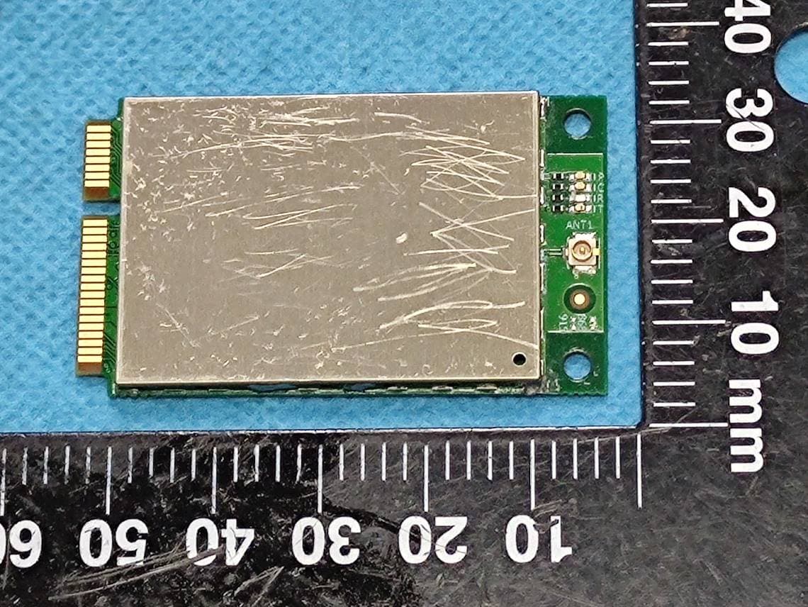
2A4G5-HLM9933
Jul 17, 2022SX1302 Gateway Module
Equipment Class
DSS - Part 15 Spread Spectrum Transmitter