2A639GA27QTA01All-in-One WorkStation
AUO Display Plus Corporation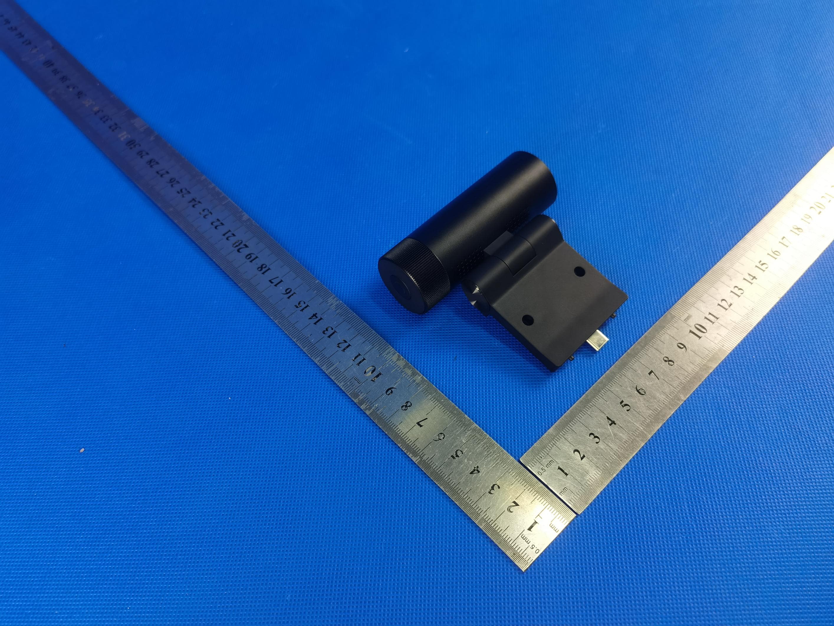
Click to zoom
Application Details
- Equipment Class
- DSS - Part 15 Spread Spectrum Transmitter
- Date of Grant
- Jul 15, 2023
- Application Purpose
- Original Equipment
- Date of Application
- Jul 15, 2023
- Equipment Note
- All-in-One WorkStation
- Frequency Range
- 2402.00000000 - 2480.00000000
- Company
- AUO Display Plus Corporation
- Country
- Taiwan
Documents & Files
Document Text
Text extracted from the exhibit documents filed with the FCC. Open a document above to read the original.
Users Manual
27" All-in-One WorkStation User Manual FCC Statement This device complies with part 15 of the FCC Rules. Operation is subject to the following two conditions: (1)This device may not cause harmful interference, and (2)this device must accept any interference received, including interference that may cause undesired operation. This equipment has been tested and found to comply with the limits for a Class B digital device, pursuant to part 15 of the FCC Rules. These limits are designed to provide reasonable protection against harmful interference in a residential installation. This equipment generates, uses and can radiate radio frequency energy and, if not installed and used in accordance with the instructions, may cause harmful interference to radio communications. However, there is no guarantee that interference will not occur in a particular installation. If this equipment does cause harmful interference to radio or television reception, which can be determined by turning the equipment off and on, the user is encouraged to try to correct the interference by one or more of the following measures: Reorient or relocate the receiving antenna. .Increase the separation between the equipment and receiver. .Connect the equipment into an outlet on a circuit different from that to which the receiver is connected. .Consult the dealer or an experienced radio/TV technician for help. Cations to this device not explicitly approved by manufacturer could Caution: .Any changes or modivoid your authority to operate this equipment.RF Exposure Information The device was evaluated to meet general RF exposure requirements. This equipment should be installed and used with a minimum distance of 20 mm between the radiator and your body. Contents Safety Precautions ............................................................................................................1 Product Introduction .........................................................................................................2 Installation .....................................................................................................................3 Adjustment ....................................................................................................................6 Instructions ....................................................................................................................7 All Menu Functions..........................................................................................................12 Parameters ...................................................................................................................17 Troubleshooting .............................................................................................................18 Warning: Excessive use may damage the eyesight. Safety Precautions 1 Please read this manual carefully before using the product and keep it in a safe place. Keep the monitor away from water sources or damp places, such as bath rooms, kitchens, basements and swimming pools. Make sure the monitor is placed on a flat surface. If the monitor falls down, it may cause human injury or device damage. Store and use the monitor in a cool, dry and well ventilated place, and keep it away from emission and heat sources. Do not cover or block the vent hole in the rear casing, and do not use the product on a bed, sofa, blanket or similar objects. The range of the supply voltage of the monitor is printed on the label on the rear casing. If it is impossible to determine the supply voltage, please consult the distributor or local power company. If the monitor will not be used for a long period, please cut off the power supply to avoid electric shock in rainy days and damage due to abnormal supply voltage. Please use a reliable grounded socket. Do not overload the socket, or it may cause fire or electric shock. Do not put foreign matters into the monitor, or it may cause short circuits resulting fire or electric shock. Do not disassemble or repair this product by self to avoid electric shock. If faults occur, please contact the after-sales service directly. Do not pull or twist the power cable forcedly. Please use a reliable grounded socket. Do not overload the socket, or it may cause fire or electric shock. Please take a 10-minute break after 30 minutes of use. Children under 2 years old should not look at the screen, and over 2 years old should not look at the screen for more than 1 hour a day. WARNING: Use of control, adjustments or procedures other than those specified in this documentation may result in exposure to shock, electrical hazards and/or mechanical hazards. 27" All-in-One WorkStation Quick Start Guide * Please read this guide carefully before using the productDownload (1)Google download (2) UM Download Link: Monitor Power cableType-C signal cableUSB A-B cable QSG Power adapter HDMI signal cable Folding standBase 2 2 Packing list Please check that the package of the monitor contains all parts. If any part is lost, please contact the distributor. The color and shape of parts may vary with models. Figures in this User Manual are for reference only. Product Introduction CameraCamera screws x2Camera rubber x2Screwdriver Stand screws x4Stylus penX-ray clip x2 Folding stand Base Stand screws x4 Accessory box 3 Installation procedure Open the package to take out foams and put them on a flat tabletop. Remove the upper foam cover and set it aside. Insert the folding stand into the rear housing of the monitor, and tighten the screws with a screwdriver. Insert the boss on the top of the base into the bottom of the stand in the direction shown in the figure, and tighten the thumb screw to lock up the folding stand and its base. Note: Please do not untie the straps in advance to avoid injury. Installation 1. 2. 3. Untie the strap Magnetic area 4 Stylus pen placement Take out the stylus pen in the accessory box, and directly magnet it to both sides of the monitor. Camera insta…
Text truncated - open the document above for the full version.
Attestation Statements
AUO DisplayPlus Corporation Theinformationprovidedin thisletteris basedon thereferencedrulepartsof Title47 of theCFRas wellas KDB986446D01. Anexpirationdateforthisletterdoesnotexist.In casetheU.S.agentchanges,thegranteeis obligatedto notifytheFCCwithin30 daysvia thegrantingTCB. FederalCommunicationsCommission Authorizationand EvaluationDivision EquipmentAuthorizationBranch 7435 OaklandMills Road Columbia,MD 21046 6/28/23 U.S. AgentDesignation AUO DisplayPlus Corporationacknowledgestheir consentfor the followingcontactlocatedin the UnitedStatesto act as their agent for serviceof processfor the equipmentfor whichauthorizationis sought(FCC ID: 2A639GA27QTA01): Nameand companyof U.S. agent:Tim Payne,FCC US Agent,LLC PhysicalU.S. addressof agent:3722 IllinoisAvenue,Saint Charles,IL, 60174,USA FRN of U.S. agent:0033402884 Email addressof U.S. agent:[email protected] FCC US Agent,LLC acknowledgestheir obligationto acceptserviceof processon behalfof AUO DisplayPlus Corporation. AUO DisplayPlus Corporationwith the FRN 0032456907acceptsits obligationto maintainan agent for serviceof processin the UnitedStatesfor no less than one year after eitherthe granteehas permanentlyterminatedall marketingand importationof the applicableequipmentwithinthe U.S., or the conclusionof any Commission-relatedadministrativeor judicialproceedinginvolvingthe equipment,whicheveris later. By signingthis form, we confirmthe aboveand that we are awareof the applicationrequirements listed under § 2.911(d)(7). Sincerely, Signature CL. Chang PrincipalEngineer AUO DisplayPlus Corporation Signature Tim Payne Manager FCC US Agent,LLC 48_[model] US_Agent_2.911(d)(7)-U, V04
External Photos
Page1of17ReportNo.:AIT23042306 FCCID:2A639GA27QTA01 PHOTOGRAPHSOFEUT AllVIEWOFEUT ADDAdapterForModelDA-180D19 Page2of17ReportNo.:AIT23042306 FCCID:2A639GA27QTA01 TOPVIEWOFEUT BOTTOMVIEWOFEUT Page3of17ReportNo.:AIT23042306 FCCID:2A639GA27QTA01 FRONTVIEWOFEUT Page4of17ReportNo.:AIT23042306 FCCID:2A639GA27QTA01 OPENVIEWOFEUT(FIGURE1) OPENVIEWOFEUT(FIGURE2)
ID Label/Location Info
Label FCC ID: 2A639GA27QTA01
Internal Photos
Page5of17ReportNo.:AIT23042306 FCCID:2A639GA27QTA01 OPENVIEWOFEUT(FIGURE3) INTERNALVIEWOFEUT(FIGURE1) Page6of17ReportNo.:AIT23042306 FCCID:2A639GA27QTA01 INTERNALVIEWOFEUT(FIGURE2) INTERNALVIEWOFEUT(FIGURE3) ANTENNA1 ANTENNABT ANTENNA0 Page7of17ReportNo.:AIT23042306 FCCID:2A639GA27QTA01 INTERNALVIEWOFEUT(FIGURE4) INTERNALVIEWOFEUT(FIGURE5) Page8of17ReportNo.:AIT23042306 FCCID:2A639GA27QTA01 INTERNALVIEWOFEUT(FIGURE6) INTERNALVIEWOFEUT(FIGURE7) Page9of17ReportNo.:AIT23042306 FCCID:2A639GA27QTA01 INTERNALVIEWOFEUT(FIGURE8) INTERNALVIEWOFEUT(FIGURE9) Page10of17ReportNo.:AIT23042306 FCCID:2A639GA27QTA01 INTERNALVIEWOFEUT(FIGURE10) INTERNALVIEWOFEUT(FIGURE11) Page11of17ReportNo.:AIT23042306 FCCID:2A639GA27QTA01 INTERNALVIEWOFEUT(FIGURE12) INTERNALVIEWOFEUT(FIGURE13) Page12of17ReportNo.:AIT23042306 FCCID:2A639GA27QTA01 INTERNALVIEWOFEUT(FIGURE14) INTERNALVIEWOFEUT(FIGURE15) Page13of17ReportNo.:AIT23042306 FCCID:2A639GA27QTA01 INTERNALVIEWOFEUT(FIGURE16) INTERNALVIEWOFEUT(FIGURE17) Page14of17ReportNo.:AIT23042306 FCCID:2A639GA27QTA01 INTERNALVIEWOFEUT(FIGURE18) INTERNALVIEWOFEUT(FIGURE19) Page15of17ReportNo.:AIT23042306 FCCID:2A639GA27QTA01 INTERNALVIEWOFEUT(FIGURE20) INTERNALVIEWOFEUT(FIGURE21) Page16of17ReportNo.:AIT23042306 FCCID:2A639GA27QTA01 INTERNALVIEWOFEUT(FIGURE22) INTERNALVIEWOFEUT(FIGURE23) Page17of17ReportNo.:AIT23042306 FCCID:2A639GA27QTA01 INTERNALVIEWOFEUT(FIGURE24) INTERNALVIEWOFAdapterModelDA-180D19 ----ENDOFREPORT----
RF Exposure Info
RF Exposure evaluation FCC ID: 2A54CGA27QTA01 Exposure category: General population/uncontrolled environment EUT Type: Production Unit Device Type: Portable 1. Reference According to §1.1307(b)(1), systems operating under the provisions of this section shall be operated in a manner that ensures that the public is not exposed to radio frequency energy level in excess of the Commission’s guidelines. According to §1.1310 and §2.1091 RF exposure is calculated. KDB447498 D01: Mobile and Portable Devices RF Exposure Procedures and Equipment Authorization Policies 2. Limit Limits for Maximum Permissible Exposure (MPE)/Controlled Exposure Frequency Range(MHz) Electric Field Strength(V/m) Magnetic Field Strength(A/m) Power Density (mW/cm²) Averaging Time (minute) Limits for Occupational/Controlled Exposure 0.3 – 3.0 3.0 – 30 30 – 300 300 – 1500 1500 – 100,000 614 1842/f 61.4 / / 1.63 4.89/f 0.163 / / (100) * (900/f 2 )* 1.0 f/300 5 6 6 6 6 6 Limits for Maximum Permissible Exposure (MPE)/Uncontrolled Exposure Frequency Range(MHz) Electric Field Strength(V/m) Magnetic Field Strength(A/m) Power Density (mW/cm²) Averaging Time (minute) Limits for Occupational/Controlled Exposure 0.3 – 3.0 3.0 – 30 30 – 300 300 – 1500 1500 – 100,000 614 824/f 27.5 / / 1.63 2.19/f 0.073 / / (100) * (180/f 2 )* 0.2 f/1500 1.0 30 30 30 30 30 F=frequency in MHz *=Plane-wave equivalent power density 3. MPE Calculation Method Predication of MPE limit at a given distance Equation from page 18 of OET Bulletin 65, Edition 97-01 S=PG/4πR² Where: S=power density P=power input to antenna G=power gain of the antenna in the direction of interest relative to an isotropic radiator R=distance to the center of radiation of the antenna 4. Antenna Information EUT can only use antennas certificated as follows provided by manufacturer; Antenna Model No. of antenna: Type of antenna: Gain of the antenna (Max.) Frequency range: WIFI-BT / Metal-supported antenna Antenna0:2.16dBi;Antenna1:1.9dBi For 2.4G Antenna 0 : 0.94dBi,Antenna 1 : 1.33dBi for 5150~5350MHz; Antenna 0 : 2.35dBi,Antenna 1 : 1.39dBi for 5360~5720MHz; Antenna 0: 2.62dBi,Antenna 1 : 1.99dBi for 5.725GHz-5.875GHz; 5. Manufacturing Tolerance Max.Conducted Power Frequency (MHz) BT 2402 2440 2480 Target (dBm) 0.91 1.78 1.61 Tolerance ± (dB) 1.0 1.0 1.0 Antenna 0 Frequency (MHz) 2.4G WIFI 2412 2437 2462 Target (dBm) 12.0 12.0 12.0 Tolerance ± (dB) 1.0 1.0 1.0 Antenna 1 Frequency (MHz) 2.4G WIFI 2412 2437 2462 Target (dBm) 11.0 11.0 11.0 Tolerance ± (dB) 1.0 1.0 1.0 Antenna 0 Frequency (MHz) 5180-5240MHz WIFI 5180 5200 5240 Target (dBm) 13 13 13 Tolerance ± (dB) 1.0 1.0 1.0 Antenna 0 Frequency (MHz) 5260-5320MHz WIFI 5260 5280 5320 Target (dBm) 12 12 12 Tolerance ± (dB) 1.0 1.0 1.0 Antenna 0 Frequency (MHz) 5500-5700MHz WIFI 5500 5600 5700 Target (dBm) 11 10 10 Tolerance ± (dB) 1.0 1.0 1.0 Antenna 0 Frequency (MHz) 5745-5825MHz WIFI 5745 5785 5825 Target (dBm) 11.5 11.5 11.5 Tolerance ± (dB) 1.0 1.0 1.0 Antenna 1 Frequency (MHz) 5180-5240MHz WIFI 5180 5200 5240 Target (dBm) 11.54 10.43 9.61 Tolerance ± (dB) 1.0 1.0 1.0 Antenna 1 Frequency (MHz) 5260-5320MHz WIFI 5260 5280 5320 Target (dBm) 9.50 9.81 11.05 Tolerance ± (dB) 1.0 1.0 1.0 Antenna 1 Frequency (MHz) 5500-5700MHz WIFI 5500 5600 5700 Target (dBm) 15.0 15.0 15.0 Tolerance ± (dB) 1.0 1.0 1.0 Antenna 1 Frequency (MHz) 5745-5825MHz WIFI 5745 5785 5825 Target (dBm) 12.0 12.0 12.0 Tolerance ± (dB) 1.0 1.0 1.0 6. Standalone MPE Result As declared by the Applicant, the EUT is a wireless device used in a fix application, at least 20 cm from any body part of the user or nearby persons; from the maximum EUT RF output power, the minimum separation distance, r =20cm, as well as the gain of the used antenna is refer to section 4, the RF power density can be obtained. Modulation Type Output power Antenna Gain (dBi) Antenna Gain (linear) MPE (mW/cm 2 ) MPE Limits (mW/cm 2 ) dBm mW BT 1.78 1.507 2.16 1.64 0.000493 1.0000 ANT 0 Modulation Type Output power Antenna Gain (dBi) Antenna Gain (linear) MPE (mW/cm 2 ) MPE Limits (mW/cm 2 ) dBm mW 2.4GHz WIFI 13.0 19.953 2.16 1.64 0.006527 1.0000 5GHz WIFI 14.0 25.11886432 2.62 1.83 0.009135 1.0000 ANT 1 Modulation Type Output power Antenna Gain (dBi) Antenna Gain (linear) MPE (mW/cm 2 ) MPE Limits (mW/cm 2 ) dBm mW 2.4GHz WIFI 12.0 15.84893192 1.90 1.55 0.004883 1.0000 5GHz WIFI 16.0 39.81071706 1.99 1.58 0.012524 1.0000 Remark: 1. Max.Output power (Peak) including turn-up tolerance; 2. MPE evaluate distance is 20cm from user manual provide by manufacturer. 3.The 2.4G WIFI and 5GHz WIFI band can not transmit simultaneously. 4.The 2.4G WIFI and BT can transmit simultaneously . SUM: 2.4GHz: ANT0+ANT1=0.006527/1+0.004883/=0.01141<1 5GHz WIFI ANT0+ANT1=0.009135/1+0.012524/1=0.021659<1 WIFI + BT (Worst)=0.021659/1+0.000493/1=0.022152<1 7. Conclusion The measurement results comply with the FCC Limit per 47 CFR 2.1091 for the uncontrolled RF Exposure of mobile device. ----------------THE END OF REPORT---------------
Test Report
Page 1 of 37 Report No.: AIT23042306FW1 Dongguan Yaxu (AiT) Technology Limited No.22, Jinqianling 3rd Street, Jitigang, Huangjiang, Dongguan, Guangdong, China. TEST REPORT Client Information: Applicant: AUO Display Plus Corporation Applicant add.: No. 1, Gongye E. 3rd Rd., East Dist., Hsinchu Science Park, Hsinchu City 30075, Taiwan Manufacturer: AUO Display Plus Corporation Manufacturer add.: No. 1, Gongye E. 3rd Rd., East Dist., Hsinchu Science Park, Hsinchu City 30075, Taiwan Product Information: Product Name: All-in-One WorkStation Model No.: GA27QTA01.X(x can be 0-9 which represents sales area code.) Brand Name: AUO Display Plus FCC ID: 2A639GA27QTA01 Applicable standards: FCC CFR Title 47 Part 15 Subpart C Section 15.247 Prepared By: Dongguan Yaxu (AiT) Technology Limited No.22, Jinqianling 3rd Street, Jitigang, Huangjiang,Dongguan, Guangdong, China Tel.: +86-769-8202 0499 Fax.: +86-769-8202 0495 Date of Receipt: 2023.04.23 Date of Test: 2023.04.23~2023.05.24 Date of Issue: 2023.05.24 Test Result: Pass This device described above has been tested by Dongguan Yaxu (AiT) Technology Limited and the test results show that the equipment under test (EUT) is in compliance with the FCC requirements. And it is applicable only to the tested sample identified in the report. Note: This report shall not be reproduced except in full, without the written approval of Dongguan Yaxu (AiT) Technology Limited, this document may be altered or revised by Dongguan Yaxu (AiT) Technology Limited, personal only, and shall be noted in the revision of the document. This test report must not be used by the client to claim product endorsement. Reviewed by: Approved by: Simba Huang Seal.chen Page 2 of 37 Report No.: AIT23042306FW1 Dongguan Yaxu (AiT) Technology Limited No.22, Jinqianling 3rd Street, Jitigang, Huangjiang, Dongguan, Guangdong, China. 1 Contents Page COVER PAGE 1 CONTENTS ......................................................................................................................................................................... 2 2 TEST SUMMARY ............................................................................................................................................................... 4 2.1 Statement of the Measurement Uncertainty ....................................................................................... 4 2.2 Measurement Uncertainty ................................................................................................................... 4 3 TEST FACILITY .................................................................................................................................................................. 5 3.1 Deviation from standard ...................................................................................................................... 5 3.2 Abnormalities from standard conditions .............................................................................................. 5 3.3 Test Location ....................................................................................................................................... 5 4 GENERAL INFORMATION .............................................................................................................................................. 6 4.1 Test frequencies .................................................................................................................................. 7 4.2 EUT Peripheral List ............................................................................................................................. 8 4.3 Test Peripheral List ............................................................................................................................. 8 4.4 TEST METHODOLOGY ..................................................................................................................... 8 4.5 Description of Test Modes ................................................................................................................... 9 5 EQUIPMENT USED DURING TEST ............................................................................................................................. 10 6 TEST RESULTS AND MEASUREMENT DATA ......................................................................................................... 11 6.1 Antenna requirement ......................................................................................................................... 11 6.2 Peak Power Measurement ............................................................................................................... 12 6.3 Frequency Separation and 20 dB Bandwidth ................................................................................... 14 6.4 Number of Hopping Frequency ......................................................................................................... 16 6.5 Time of Occupancy (Dwell Time) ...................................................................................................... 17 6.6 Conducted Spurious Emissions and Band Edges Test .................................................................... 19 6.7 Restrict-band Band-edge Measurements ......................................................................................... 21 6.8 Radiated Emissions Measurement ................................................................................................... 23 6.9 Conducted Emissions ....................................................................................................................... 33 6.10 Pseudorandom frequency hopping sequence ................................................................................ 36 7 TEST SETUP PHOTOGRAPHS OF EUT ..................................................................................................................... 37 8 EXTERNAL PHOTOGRAPHS OF EUT ........................................................................…
Text truncated - open the document above for the full version.
Test Report
Antenna 0 ANT0 Antenna 1 ANT1
Test Report
Dongguan Yaxu(AiT) Technology Limited Report No.: AIT23042306FW1 FCC ID: 2A639GA27QTA01 Page 1 of 61 Appendix A_Test Data for BT(BDR/EDR) Conducted Measurement Product Name:All-in-One WorkStation Model No.: GA27QTA01.X Brand Name:AUO Display Plus Environmental Conditions Temperature: 24°C Relative Humidity: 51% ATM Pressure: 101Kpa Test Engineer: Simba Huang Supervised by: Seal Chen Dongguan Yaxu(AiT) Technology Limited Report No.: AIT23042306FW1 FCC ID: 2A639GA27QTA01 Page 2 of 61 Contents Page COVER PAGE 1 Duty Cycle ............................................................................................................................................................................................. 3 1.1 Test Result .................................................................................................................................................................................. 3 1.2 Test Graphs ................................................................................................................................................................................. 4 2 Maximum Conducted Peak Output Power ............................................................................................................................................. 9 2.1 Test Result .................................................................................................................................................................................. 9 2.2 Test Graphs ............................................................................................................................................................................... 10 3 20dB Bandwidth .................................................................................................................................................................................. 15 3.1 Test Result ................................................................................................................................................................................ 15 3.2 Test Graphs ............................................................................................................................................................................... 16 4 Carrier Frequency Separation.............................................................................................................................................................. 21 4.1 Test Result ................................................................................................................................................................................ 21 4.2 Test Graphs ............................................................................................................................................................................... 22 5 Hopping Channel Number ................................................................................................................................................................... 24 5.1 Test Result ................................................................................................................................................................................ 24 5.2 Test Graphs ............................................................................................................................................................................... 25 6 Dwell Time ........................................................................................................................................................................................... 27 6.1 Test Result ................................................................................................................................................................................ 27 6.2 Test Graphs ............................................................................................................................................................................... 28 7 RF Conducted Spurious Emissions ..................................................................................................................................................... 31 7.1 Test Result ................................................................................................................................................................................ 31 7.2 Test Graphs ............................................................................................................................................................................... 32 8 Band-edge for RF Conducted Emissions ............................................................................................................................................. 41 8.1 Test Result ................................................................................................................................................................................ 41 8.2 Test Graphs ............................................................................................................................................................................... 42 9 Restrict-band band-edge measurements ............................................................................................................................................. 54 9.1 Test Result ................................................................................................................................................................................ 54 9.2 Test Graphs ............................................................................................................................................................................... 56 Dongguan Yaxu(AiT) Technology Limited Report No.: AIT23042306FW1 FCC ID: 2A639GA27QTA01 Page 3 of 61 1 Duty Cycle 1.1 Test Result Mode Frequency (MHz) Duty Cycle (%) 1/T (kHz) 1-DH1 2402 31.2 2.63 1-DH1 2441 31.2 2.63 1-DH1 2480 31.2 2.6…
Text truncated - open the document above for the full version.
Test Setup Photos
FCCID:2A639GA27QTA01 RadiatedEmissions FCCID:2A639GA27QTA01 ConductedEmissions
Contact Information
Applicant
CL. Chang(Principal Engineer)
Test Firm
Dongguan Yaxu (AiT) Technology LimitedCoin Tang
[email protected]+86 0769-82020499-21
Technical Specifications
| # | Rule Parts | Frequency Range | Power Output |
|---|---|---|---|
| 1 | 15C | 2.40 GHz - 2.48 GHz | 1.40 mW |
Other Applications from AUO Display Plus Corporation
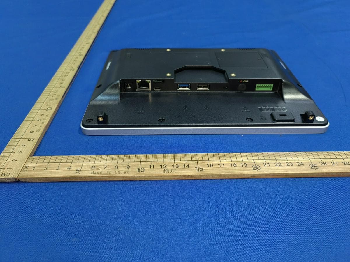
2A639-P1000-R
Feb 20, 2024Panel PC
Equipment Class
DTS - Digital Transmission System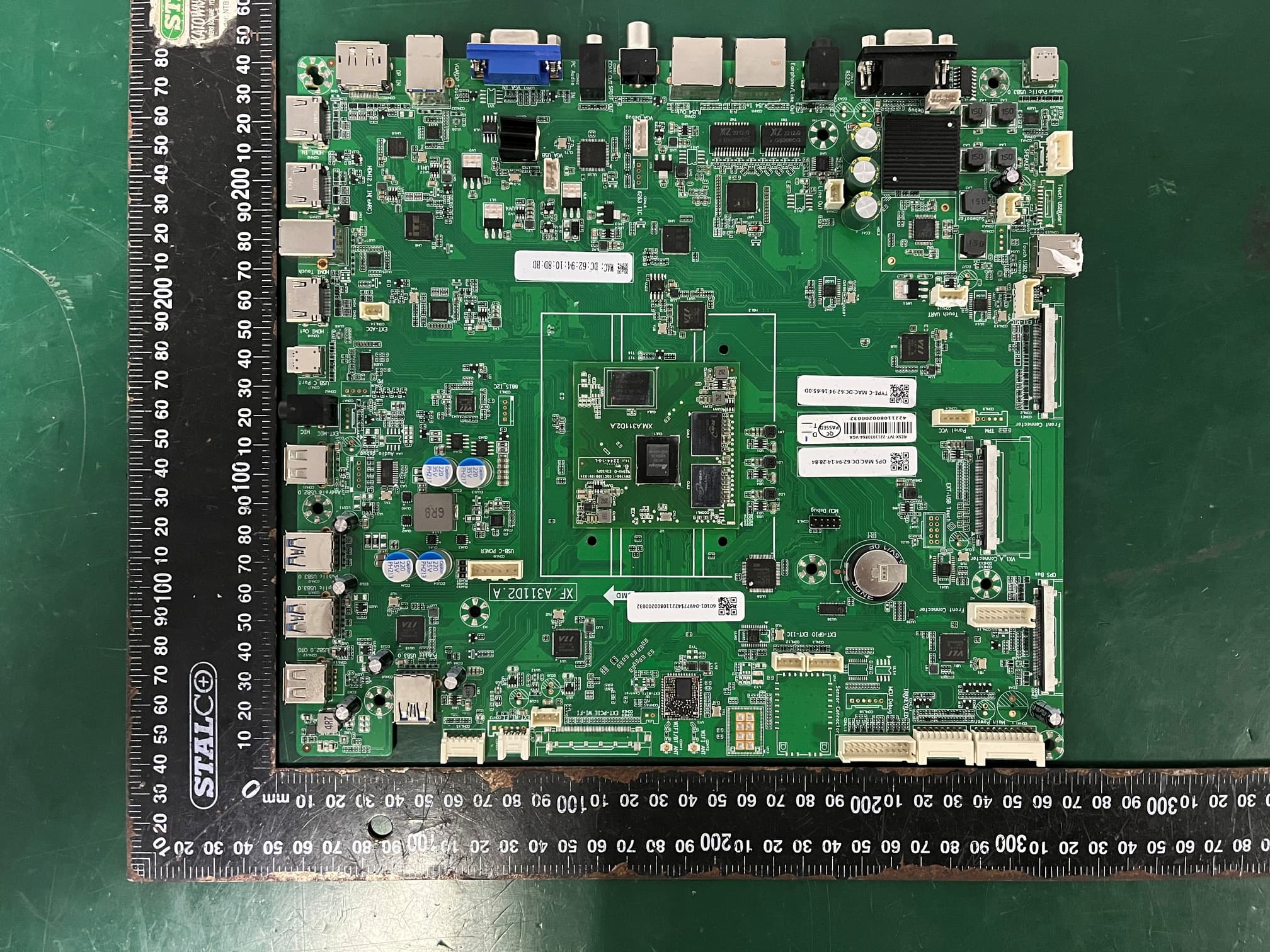
2A639-AP6575P
May 10, 2023WIFI Module
Equipment Class
NII - Unlicensed National Information Infrastructure TX