2A6YY-E1Bluetooth earbuds with real-time translation capabilities
Vasco Electronics Goralski Group S.K.A.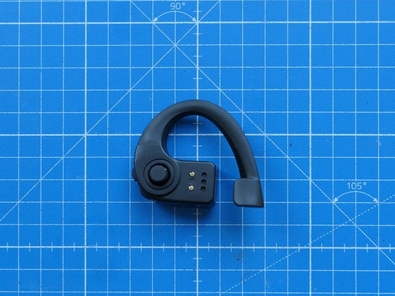
Click to zoom
Application Details
- Equipment Class
- DTS - Digital Transmission System
- Date of Grant
- Dec 02, 2024
- Application Purpose
- Original Equipment
- Date of Application
- Dec 02, 2024
- Equipment Note
- Bluetooth earbuds with real-time translation capabilities
- Frequency Range
- 2402.00000000 - 2480.00000000
- Country
- Poland
Documents & Files
Document Text
Text extracted from the exhibit documents filed with the FCC. Open a document above to read the original.
Users Manual
Quick Start Guide Vasco Translator E1 www.vasco-translator.com Table of contents 1.Quick Start Guide 3 2.Security & Warranty Conditions 27 3.Compliance information & Statement 33 3 1 4 2 5 100%-90%89%-51%50%-26% 26%-6%<5%0% 100% – 4 LEDs 1%-99% – 1->4 LEDs 6 Can't see your earbud? Tap here. Vasco Earbud Vasco Earbud 3 BC 7 Can't see your earbud? Tap here. Go to conversation My earbud English (UK) Volume: 100%, Battery: 100% D 8 E 3 9 4 10 A 4 11 B 12 C 4 13 4 14 Go to conversation A 4 15 B 16 C 4 17 5 18 Version: 1.0.0 5 19 B 6 20 D 6 21 English 1– Buttons Volume buttons – use +/- it to increase or decrease the volume. Push-to-talk button – press the earbud against your ear and release it to start the speech recognition process, and begin talking. 2– Charging case Earbuds charging – place the earbuds inside the charging case and close it to begin charging. Case charging – connect the charging case to the USB AC adapter (commercially available) or to a PC using the USB cable (supplied). The rating of the charging output should be DC 5V, at least 0.5A. The battery level of the charging case is represented by the LED indicator. 3– First-time use – using the mobile app Download and install the Vasco Connect app on your smartphone. This is a dedicated mobile app for use with Vasco Translator E1. You can download it from the following: • the App Store (devices with iOS systems) • the Google Play Store (devices with Android systems). Run the Vasco Connect app – once you have downloaded and installed Vasco Connect on your smartphone, run the app. 22 Take the earbuds out of the charging case to turn them on. The pairing process will begin automatically, and the earbuds should be found by Vasco Connect and listed in the app. Allow the mobile app to access the location and Bluetooth connection on your smartphone. Select your earbud from the list in the app. It will light up and connect. Personalize your earbud. Type a name, select your lan- guage, set a volume level, and select the color in which your earbud is to light up. You can add another earbud and repeat the process, or immediately start using your earbud. If you wish to unpair the earbud from your mobile phone, choose “Forget” from the drop-down list in the app or press the Volume Up and Volume Down buttons on the earbud simultaneously for 3 seconds. If you wish to restore your earbud to its default settings, press the Volume Up and Volume Down buttons on the earbud simultaneously for 10 seconds. 4– Conversation Start the conversation – put your earbud on and tap “Go to conversation”. Now you can switch between the translation modes you prefer. Loudspeaker mode – this allows you to use both the earbuds and the mobile app to communicate with someone else. This is 23 the default mode when you have only one earbud paired, but you may also use it with more earbuds that are connected to the app. Select the language of your conversation partner by choos- ing the right option from the drop-down list. Press the earbud against your ear, release it and start talking. The translated text will appear on the screen and play through a speaker. Tap the icon in the app to begin translating the other per- son’s speech.You will hear the translation in your earbud and see its visual transcription on the screen. Earbuds mode – it allows you to talk directly with 2 or more people using earbuds that are paired with a single mobile app. Pair the earbuds with the Vasco Connect app and person- alize them (set the name, language, volume and color). Press the earbud against your ear and release it to start talking. Once you have finished speaking, the translated text will appear on the screen and play through the earbuds of your conversation partners. Now your conversation partner can press and release their earbud to start talking. The translated text will appear on the screen and play into your earbud. You can also choose touchless translation. Once enabled, you don’t have to press the earbud. Just start speaking and the device will automatically translate your conversation. Finish the conversation – once you have finished the conversa- tion, place your earbud back into the charging case. 24 5– Settings Tutorials – you can check the instructions on how to use your earbuds at any time by running tutorials from the settings menu, which you can find in the mobile app. Updates – you can easily check for updates to your earbuds and to the mobile app. Press the button in the settings menu to proceed with the update process. 6– First-time use – using the handheld Vasco Translator* You can connect your earbuds to the handheld Vasco Translator and enjoy the advantages of this bundle. Please turn on the handheld Vasco Translator and take the earbuds out of the charging case. Make sure that your handheld Vasco Translator is updated to the latest version. Tap the earbud icon in the device’s main menu. The pairing process will begin automatically, and the earbuds should be found by Vasco Translator and listed in the app. Follow the B, C, D steps in the section “First-time use – using the mobile app”. *Works on selected models only, for instance Vasco Translator V4. If you wish to unpair the earbud from your mobile phone and connect it to the handheld Vasco Translator, you can: • Open the Vasco Connect app on your phone and select “Forget” next to your earbud, or • Press both Volume Up and Down buttons on the earbud at the same time for 3 seconds. If you wish to restore your earbud to its default settings, press the Volume Up and Volume Down buttons on the earbud simultaneously for 10 seconds. 25 Warranty & Conditions ENGLISH Security WARNING: Read the following instructions carefully in order to minimize the risk associated with the use of the device. Failure to follow these rules may result in damage to the device or may be hazardous to your health. • Do not use the device during takeoff or landing of the plane. Respect all rules set by the crew. Mobile devices may disrupt on-…
Text truncated - open the document above for the full version.
Attestation Statements
VA.SCO Vasco Electronics Goralski Group S.K.A. aleja 29 Listopada 20 31 -401 Krakow Poland Federal Communication Commission Authorization and Evaluation Division 7435 Oakland Mills Road Columbia, MD 21046 USA November 13th, 2024 Attestation Statement according to 2.91l(d)(S)(i) and 2.911(d)(S)(ii) FCC ID: 2A6YY-El FRN: 0032430258 TO WHOM IT M AY CONCERN: Hereby we certify that the equipment for which authorization is sought is not "covered" equipment prohibited from receiving an equipment authorization pursuant to section 2.903 of the FCC rules. Further we certify that, as of the date of the filing of the application, Vasco Electronics Goralski Group S.K.A. is not identified on the Covered List as an entity producing "covered" equipment. Sincerely, r ,,gors:m� / . _-____ ar[ment Vas Gr 1 1 11 ', : 1 :'1 (signature & company stamp) Vasco Electronics Goralski Group S.l<.A. Vasco Electronics Goralski Group S.K.A. Al. 29 Listopada 20, 31-401 Krakow, Polska NIP: 6772369151 REGON: 122581850 aleja 29 Listopada 20, 31-401 Krakow, Poland Igor Sumara +48 602741232 i .su ma ra i@vasco-e lectron ics.com
Attestation Statements
VASCO Vasco Electronics Goralski Group S.l<.A. aleja 2 9 Listopada 20 31-401 Krakow Pol and F ederal Communication Commission A uthorization and Evaluation Division 7435 Oakland Mills Road Columbia, MD 21046 U SA November 13th, 2024 Attestation Statement according to 2.9ll{d)(7) FCC ID: 2A6YY-El FRN: 0032430258 TO W HOM IT MAY CONCERN: We, Vasco Electronics Goralski Group S.K.A. designate Vasco Electronics LLC, 800 N King, Street, Suite 304, Wilmington, DE 19801 to act as U.S. agent for service of process. Vasco Electronics LLC hereby acknowledges the obligation of the U.S. agent for service of process. Further Vasco Electronics Goralski Group S.K.A. accepts to maintain an agent for no less than o ne year after the grantee has terminated all marketing and importation or the conclusion of any Commission-related proceeding involving the equipment. Since:rely ,� /; ' i� o r Sum � / Vasco Electronics Goralski Grou p S.K.A. 1 ,. . � · Al. 29 Listopada 20, 31- 401 Krakow, Polska HeagA:i � � �B'r Jef e p rnimen t NIP: 6772369151 REGON: 122581850 Vasco Eioctrzrncs G6ra/sid Group S.K A !(signature & company stamp} Vasco Electronics Goralski Group S.K.A. aleja 29 Listopada 20, 31-401 Krakow, Poland Igor Sumara +48 602741232 [email protected] Vasco Electr ics LLC, 800 N King Street, Suite 304, Wilmington, DE 19801 USA Maciej Goralski 7024460714 [email protected]
External Photos
Annex A101 - Photographs No.1-8302-24-01-01_TR1-A101-R01 November 15, 2024 DescriptionExternal photographs of EUT This document is electronically signed and valid without handwritten signature. Public keys for verification of the electronic signatures can be requested at the testing laboratory. Authorized Michael Dorongovski Lab Manager Radio Labs cetecom advanced GmbH Untertürkheimer Str. 6-10, 66117 Saarbrücken Document No. 1-8302-24-01-01_TR1-A101-R01 Release 1 - Page 1 of 2 Photo 1 Photo 2 - END OF DOCUMENT - cetecom advanced GmbH Untertürkheimer Str. 6-10, 66117 Saarbrücken Document No. 1-8302-24-01-01_TR1-A101-R01 Release 1 - Page 2 of 2
ID Label/Location Info
How to find the FCC ID number? For smartphone users: Open the Vasco Connect app. For Vasco V4 translator users: Enter ‘Earbuds’ view Then, there are 2 ways to find the FCC ID number. Tap the information icon. You can access it when you don’t have any earbuds paired yet. Check the screen below. 1 2A6YY-E1 Tap the Settings drop-down menu and then choose the FCC ID panel. This option is available when you have already paired Vasco Translator E1. Check the screens below. 2 2A6YY-E1 2A6YY-E1 The FCC ID number can also be found on the back of the giftbox, as shown in the picture:
Internal Photos
Annex A102 - Photographs No.1-8302-24-01-01_TR1-A102-R01 November 15, 2024 DescriptionInternal photographs of EUT This document is electronically signed and valid without handwritten signature. Public keys for verification of the electronic signatures can be requested at the testing laboratory. Authorized Michael Dorongovski Lab Manager Radio Labs cetecom advanced GmbH Untertürkheimer Str. 6-10, 66117 Saarbrücken Document No. 1-8302-24-01-01_TR1-A102-R01 Release 1 - Page 1 of 3 Photo 1 Photo 2 cetecom advanced GmbH Untertürkheimer Str. 6-10, 66117 Saarbrücken Document No. 1-8302-24-01-01_TR1-A102-R01 Release 1 - Page 2 of 3 Photo 3 - END OF DOCUMENT - cetecom advanced GmbH Untertürkheimer Str. 6-10, 66117 Saarbrücken Document No. 1-8302-24-01-01_TR1-A102-R01 Release 1 - Page 3 of 3
RF Exposure Info
© cetecom advanced GmbH Page 1 of 12 TEST REPORT Test report no.: 1-8302-24-01-04_TR2-R01 Testing laboratory Applicant cetecom advanced GmbH Untertuerkheimer Strasse 6 – 10 66117 Saarbruecken / Germany Phone: + 49 681 5 98 - 0 Fax: + 49 681 5 98 - 9075 Internet: https://cetecomadvanced.com e-mail: [email protected] Accredited Testing Laboratory: The testing laboratory (area of testing) is accredited according to DIN EN ISO/IEC 17025 (2018-03) by the Deutsche Akkreditierungsstelle GmbH (DAkkS). The accreditation is valid for the scope of testing procedures as stated in the accreditation certificate with the registration number: D-PL-12047-01-00. ISED Testing Laboratory Recognized Listing Number: DE0001 FCC designation number: DE0002 Vasco Electronics Góralski Group S.K.A. al. 29 Listopada 20 31-401 Kraków / POLAND Phone: -/ - Contact: Karol Osuchowski e-mail: [email protected] Manufacturer Vasco Electronics Góralski Group S.K.A. al. 29 Listopada 20 31-401 Kraków / POLAND Test Item Kind of test item: Bluetooth earbud with real-time translation capabilities Model name: Vasco Translator E1 FCC ID: 2A6YY-E1 Frequency: 2400 MHz to 2483.5 MHz Technology tested: Bluetooth® LE This test report is electronically signed and valid without handwritten signature. For verification of the electronic signatures, the public keys can be requested at the testing laboratory. Test report authorized: Test performed: Alexander Hnatovskiy Eric Tuettmann Lab Manager Testing Manager Radio Labs Radio Labs Test report no.: 1-8302-24-01-04_TR2-R01 © cetecom advanced GmbH Page 2 of 12 1 Table of contents 1 Table of contents ............................................................................................................................................. 2 2 General Information ......................................................................................................................................... 3 2.1 Notes and Disclaimer ............................................................................................................................ 3 2.2 References ............................................................................................................................................ 3 2.3 Structure of this Document ................................................................................................................... 3 3 General RF Exposure Test Exemptions ............................................................................................................ 4 3.1 1 mW Test Exemption ........................................................................................................................... 5 3.2 MPE- Based Test Exemption ................................................................................................................. 5 3.3 SAR-Based Test Exemption .................................................................................................................. 5 3.4 Simultaneous Transmission ............................................................................................................... 6 4 1 mW Test Exemption ...................................................................................................................................... 7 4.1 Detailed Description .............................................................................................................................. 7 4.2 Results ................................................................................................................................................... 7 5 MPE-Based Test Exemption ............................................................................................................................ 8 5.1 Detailed Description .............................................................................................................................. 8 5.2 Results ................................................................................................................................................... 8 6 SAR-Based Test Exemption ............................................................................................................................. 9 6.1 Detailed Description .............................................................................................................................. 9 6.2 Results ................................................................................................................................................. 10 7 Simultaneous Transmission .......................................................................................................................... 11 7.1 Detailed Description ............................................................................................................................ 11 7.2 Result................................................................................................................................................... 11 8 Conclusion ...................................................................................................................................................... 12 Test report no.: 1-8302-24-01-04_TR2-R01 © cetecom advanced GmbH Page 3 of 12 2 General Information 2.1 Notes and Disclaimer The test results of this test report relate exclusively to the test item specified in this test report. cetecom advanced GmbH does not assume responsibility for any conclusions and generalizations drawn from the test results with regard to other specimens or samples of the type of the equipment represented by the test item. The test report may only be reproduced or published in full. Reproduction or publication of extracts from the report requires the prior written approval of cetecom advanced GmbH. The testing service provided by cetecom advanced GmbH has been rendered under the current "General Terms and Conditions for cetecom advanced GmbH". cetecom advanced GmbH will …
Text truncated - open the document above for the full version.
Test Report
Conducted test results No.1-8302-24-01-06_TR1-A201-R1 August 08, 2024 Test Standard(s)FCC 15.247 - NI FCC 15.247, ISED RSS247 - NI NA - NI This document is electronically signed and valid without handwritten signature. Public keys for verification of the electronic signatures can be requested at the testing laboratory. Authorized Michael Dorongovski Lab Manager Radio Labs cetecom advanced GmbH Untertürkheimer Str. 6-10, 66117 Saarbrücken Document No. 1-8302-24-01-06_TR1-A201-R1 Release 1 - Page 1 of 128 Table of Content FCC 15.247 # Bandwidth 6dB DTS ~ BT LE 2 Msps3 FCC 15.247 # Bandwidth 6dB DTS ~ BT LE 2 Msps6 FCC 15.247 # Bandwidth 6dB DTS ~ BT LE 2 Msps9 FCC 15.247 # Bandwidth 6dB DTS ~ BT LE 1 Msps12 FCC 15.247 # Bandwidth 6dB DTS ~ BT LE 1 Msps15 FCC 15.247 # Bandwidth 6dB DTS ~ BT LE 1 Msps18 FCC 15.247, ISED RSS247 # Bandwidth 99PCT and 20dB ~ BT LE 2 Msps21 FCC 15.247, ISED RSS247 # Bandwidth 99PCT and 20dB ~ BT LE 2 Msps26 FCC 15.247, ISED RSS247 # Bandwidth 99PCT and 20dB ~ BT LE 2 Msps31 FCC 15.247, ISED RSS247 # Bandwidth 99PCT and 20dB ~ BT LE 1 Msps36 FCC 15.247, ISED RSS247 # Bandwidth 99PCT and 20dB ~ BT LE 1 Msps41 FCC 15.247, ISED RSS247 # Bandwidth 99PCT and 20dB ~ BT LE 1 Msps46 FCC 15.247 # Maximum peak conducted output power DTS ~ BT LE 2 Msps51 FCC 15.247 # Maximum peak conducted output power DTS ~ BT LE 2 Msps55 FCC 15.247 # Maximum peak conducted output power DTS ~ BT LE 2 Msps59 FCC 15.247 # Maximum peak conducted output power DTS ~ BT LE 1 Msps63 FCC 15.247 # Maximum peak conducted output power DTS ~ BT LE 1 Msps67 FCC 15.247 # Maximum peak conducted output power DTS ~ BT LE 1 Msps71 FCC 15.247 # Peak psd DTS ~ BT LE 2 Msps75 FCC 15.247 # Peak psd DTS ~ BT LE 2 Msps78 FCC 15.247 # Peak psd DTS ~ BT LE 2 Msps81 FCC 15.247 # Peak psd DTS ~ BT LE 1 Msps84 FCC 15.247 # Peak psd DTS ~ BT LE 1 Msps87 FCC 15.247 # Peak psd DTS ~ BT LE 1 Msps90 FCC 15.247 # TX spurious conducted 20dBc ~ BT LE 2 Msps93 FCC 15.247 # TX spurious conducted 20dBc ~ BT LE 2 Msps97 FCC 15.247 # TX spurious conducted 20dBc ~ BT LE 2 Msps101 FCC 15.247 # TX spurious conducted 20dBc ~ BT LE 1 Msps105 FCC 15.247 # TX spurious conducted 20dBc ~ BT LE 1 Msps109 FCC 15.247 # TX spurious conducted 20dBc ~ BT LE 1 Msps113 NA # Peak output power 3MHz/3MHz ~ BT LE 1 Msps117 NA # Peak output power 3MHz/3MHz ~ BT LE 1 Msps121 NA # Peak output power 3MHz/3MHz ~ BT LE 1 Msps125 cetecom advanced GmbH Untertürkheimer Str. 6-10, 66117 Saarbrücken Document No. 1-8302-24-01-06_TR1-A201-R1 Release 1 - Page 2 of 128 FCC 15.247 # Bandwidth 6dB DTS ~ BT LE 2 Msps References TC start23.07.2024 13:27:20 Ambit temp [°C] | humidity [rel%] 24.8 | 58 System version5.0.7.2 Standard | Version FCC 15.247 | NI Method DescriptionFCC 15.247 Bandwidth 6dB DTS - BT LE 2 Msps Information EUT Common Settings BT Low Energy Intermodulation Value N 3 Image Freq. Low | Mid | High [MHz] 0 | 0 | 0 Power Class2 1 Mbps supported True | TXpayload 255 | RXpayload 255 2 Mbps supported True | TXpayload 255 | RXpayload 255 Longrange S8 supported False | TXpayload 255 | RXpayload 255 Longrange S2 supportedFalse | TXpayload 255 | RXpayload 255 Signaling Settings None | HCI | 1 | 2400 | None | S1 | None | On Signaling RF Settings RF1com | 0 | 0 | On | User Interaction No Equipment Signal analyzer,Rohde&Schwarz,FSV-40,1307.9002K40/101042,3.70 Switch matrix,cetecom advanced GmbH,USM,B002,1.0.0 Test Parameter Technology to testBT LE 2 Msps EUT portEUT1 Temperaturenom Voltagenom Frequency low to testFalse | Freq [MHz] 2404 Frequency mid to testFalse | Freq [MHz] 2440 Frequency high to testTrue | Freq [MHz] 2478 Auto control enabled power supply | Climatic Box No | No Additional path loss [dB]0.7 Full path typeEUT_SA_GEN_SIG Full path nameEUT1.MP.SIG1/EUT1.SA/EUT1.GEN1/EUT1.GEN2/ cetecom advanced GmbH Untertürkheimer Str. 6-10, 66117 Saarbrücken Document No. 1-8302-24-01-06_TR1-A201-R1 Release 1 - Page 3 of 128 Test Parameter Switch bits 00010001:00010001:00000000:00000001 cetecom advanced GmbH Untertürkheimer Str. 6-10, 66117 Saarbrücken Document No. 1-8302-24-01-06_TR1-A201-R1 Release 1 - Page 4 of 128 Test at TX 2478 MHz RESULT: Reference power cond. DESCRIPTIONLOWER LIMITUPPER LIMITMEASUREDUNITVERDICT Ref. power 1MHz/1MHz cond. -------0.09dBmINFO Ref. frequency------2478.500MHzINFO READ SA SETTINGS: RefLevel [dBm] | RefLevelOffset [dB] | InpAtt [dB]4.91 | 11.32 | 10 Start [MHz] | Stop [MHz]2475.700 | 2480.300 RBW [MHz] | VBW [MHz]0.100000 | 0.300000 Detector | TraceModePOS | MAXH Sweep: time [ms] | count | points per Section | type50 | 200 | 10001 | SWE 2476.002476.502477.002477.502478.002478.502479.002479.502480.00 MHz Frequency 0.0 -5.0 -10.0 -15.0 -20.0 -25.0 -30.0 -35.0 -40.0 -45.0 -50.0 dBm Magnitude BW 6dB RESULT DESCRIPTIONLOWER LIMITUPPER LIMITMEASUREDUNITVERDICT DTS bandwidth (6dB)500---1128kHzPASS Verdict PASS cetecom advanced GmbH Untertürkheimer Str. 6-10, 66117 Saarbrücken Document No. 1-8302-24-01-06_TR1-A201-R1 Release 1 - Page 5 of 128 FCC 15.247 # Bandwidth 6dB DTS ~ BT LE 2 Msps References TC start23.07.2024 13:09:32 Ambit temp [°C] | humidity [rel%] 24.8 | 56 System version5.0.7.2 Standard | Version FCC 15.247 | NI Method DescriptionFCC 15.247 Bandwidth 6dB DTS - BT LE 2 Msps Information EUT Common Settings BT Low Energy Intermodulation Value N 3 Image Freq. Low | Mid | High [MHz] 0 | 0 | 0 Power Class2 1 Mbps supported True | TXpayload 255 | RXpayload 255 2 Mbps supported True | TXpayload 255 | RXpayload 255 Longrange S8 supported False | TXpayload 255 | RXpayload 255 Longrange S2 supportedFalse | TXpayload 255 | RXpayload 255 Signaling Settings None | HCI | 1 | 2400 | None | S1 | None | On Signaling RF Settings RF1com | 0 | 0 | On | User Interaction No Equipment Signal analyzer,Rohde&Schwarz,FSV-40,1307.9002K40/101042,3.70 Switch matrix,cetecom advanced GmbH,USM,B002,1.0.0 Test Parameter Technology to testBT LE 2 Msps EUT portEUT1 Temperaturenom Voltagenom Frequency low to testFalse | Freq [MHz] 2404 Frequency mid to testT…
Text truncated - open the document above for the full version.
Test Report
TEST REPORT Test report no.: 1-8302-24-01-06_TR1-R01 Testing laboratory Applicant cetecom advanced GmbH Untertuerkheimer Strasse 6 – 10 66117 Saarbruecken / Germany Phone: + 49 681 5 98 - 0 Fax: + 49 681 5 98 - 9075 Internet: https://cetecomadvanced.com e-mail: [email protected] Accredited Testing Laboratory: The testing laboratory (area of testing) is accredited according to DIN EN ISO/IEC 17025 (2018-03) by the Deutsche Akkreditierungsstelle GmbH (DAkkS). The accreditation is valid for the scope of testing procedures as stated in the accreditation certificate with the registration number: D-PL-12047-01-00. ISED Testing Laboratory Recognized Listing Number: DE0001 FCC designation number: DE0002 Vasco Electronics Góralski Group S.K.A. al. 29 Listopada 20 31-401 Kraków / POLAND Phone: -/- Contact: Karol Osuchowski e-mail: [email protected] Manufacturer Vasco Electronics Góralski Group S.K.A. al. 29 Listopada 20 31-401 Kraków / POLAND Test standard/s FCC - Title 47 CFR Part 15 FCC - Title 47 of the Code of Federal Regulations; Chapter I; Part 15 - Radio frequency devices RSS - 247 Issue 3 Digital Transmission Systems (DTSs), Frequency Hopping Systems (FHSs) and Licence-Exempt Local Area Network (LE-LAN) Devices For further applied test standards please refer to section 3 of this test report. Test Item Kind of test item: Bluetooth earbud with real-time translation capabilities Model name: Vasco Translator E1 FCC ID: 2A6YY-E1 ISED certification number: 27609-E1 Frequency: 2400 MHz to 2483.5 MHz Technology tested: Bluetooth ® LE Antenna: Integrated antenna Power supply: 3.7 V DC by Li-Ion battery Temperature range: 0°C to +45°C This test report is electronically signed and valid without handwritten signature. For verification of the electronic signatures, the public keys can be requested at the testing laboratory. Test report authorized: Test performed: On behalf of Marco Bertolino Michael Dorongovski Supervisor Radio Services Lab Manager Radio Labs Radio Labs Test report no.: 1-8302-24-01-06_TR1-R01 © cetecom advanced GmbH Page 2 of 42 1 Table of contents 1 Table of contents ....................................................................................................................................... 2 2 General information ................................................................................................................................... 3 2.1 Notes and disclaimer ...................................................................................................................... 3 2.2 Application details .......................................................................................................................... 3 2.3 Test laboratories sub-contracted .................................................................................................... 3 3 Test standard/s, references and accreditations ......................................................................................... 4 4 Reporting statements of conformity – decision rule .................................................................................. 5 5 Test environment ...................................................................................................................................... 6 6 Test item ................................................................................................................................................... 6 6.1 General description ......................................................................................................................... 6 6.2 Additional information .................................................................................................................... 6 7 Sequence of testing ................................................................................................................................... 7 7.1 Sequence of testing radiated spurious 9 kHz to 30 MHz ................................................................. 7 7.2 Sequence of testing radiated spurious 30 MHz to 1 GHz ................................................................. 8 7.3 Sequence of testing radiated spurious 1 GHz to 18 GHz ................................................................. 9 7.4 Sequence of testing radiated spurious above 18 GHz.................................................................... 10 8 Description of the test setup .................................................................................................................... 11 8.1 Shielded semi anechoic chamber .................................................................................................. 12 8.2 Shielded fully anechoic chamber ................................................................................................... 13 8.3 Radiated measurements > 18 GHz ................................................................................................ 14 8.4 Conducted measurements system ................................................................................................ 15 9 Measurement uncertainty ........................................................................................................................ 16 10 Summary of measurement results .................................................................................................... 17 11 Additional comments ........................................................................................................................ 18 12 Measurement results ........................................................................................................................ 19 12.1 System gain ............................................................................................................................... 19 12.2 Power spectral density .............................................................................................................. 20 12.3 DTS bandwidth …
Text truncated - open the document above for the full version.
Test Setup Photos
Annex A103 - Photographs No.1-8302-24-01-01_TR1-A103-R01 November 15, 2024 DescriptionTest set-up photographs This document is electronically signed and valid without handwritten signature. Public keys for verification of the electronic signatures can be requested at the testing laboratory. Authorized Michael Dorongovski Lab Manager Radio Labs cetecom advanced GmbH Untertürkheimer Str. 6-10, 66117 Saarbrücken Document No. 1-8302-24-01-01_TR1-A103-R01 Release 1 - Page 1 of 5 Photo 1 Photo 2 cetecom advanced GmbH Untertürkheimer Str. 6-10, 66117 Saarbrücken Document No. 1-8302-24-01-01_TR1-A103-R01 Release 1 - Page 2 of 5 Photo 3 Photo 4 cetecom advanced GmbH Untertürkheimer Str. 6-10, 66117 Saarbrücken Document No. 1-8302-24-01-01_TR1-A103-R01 Release 1 - Page 3 of 5 Photo 5 Photo 6 cetecom advanced GmbH Untertürkheimer Str. 6-10, 66117 Saarbrücken Document No. 1-8302-24-01-01_TR1-A103-R01 Release 1 - Page 4 of 5 Photo 7 - END OF DOCUMENT - cetecom advanced GmbH Untertürkheimer Str. 6-10, 66117 Saarbrücken Document No. 1-8302-24-01-01_TR1-A103-R01 Release 1 - Page 5 of 5
Contact Information
Applicant
Peggy zhu(sales director)
Test Firm
cetecom advanced GmbHGerald Schmidt
Technical Specifications
| # | Rule Parts | Frequency Range | Power Output |
|---|---|---|---|
| 1 | 15C | 2.40 GHz - 2.48 GHz | 1.12 mW |
Other Applications from Vasco Electronics Goralski Group S.K.A.
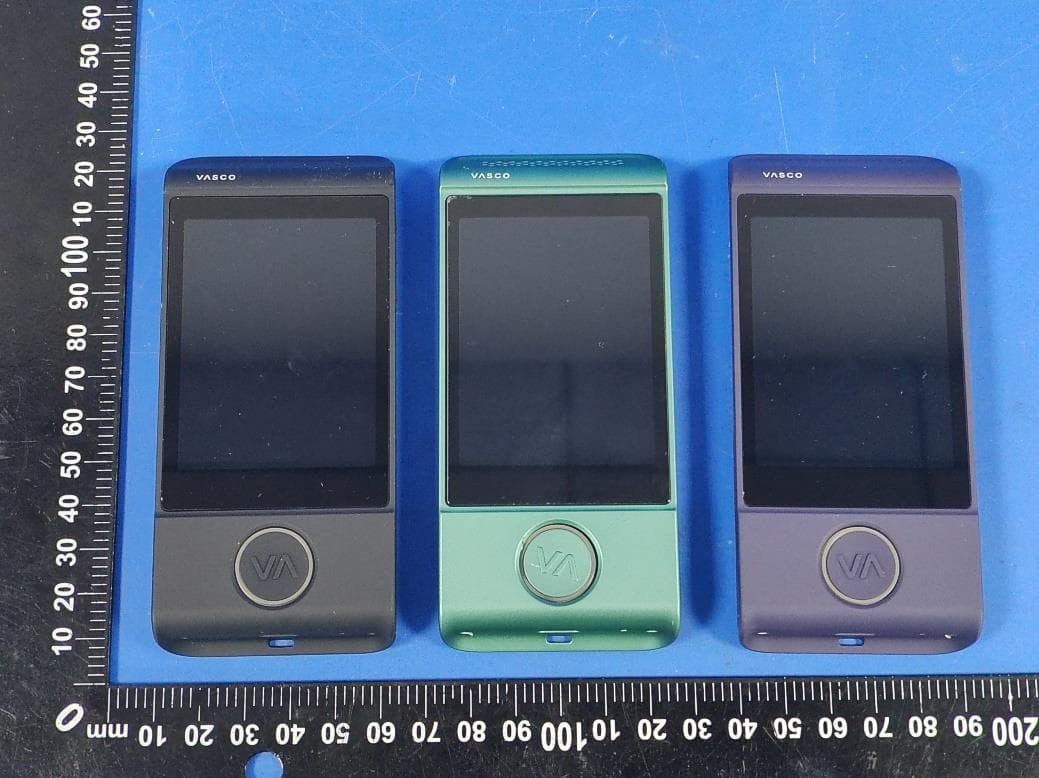
2A6YY-M4
Mar 17, 2026Vasco Translator M4
Equipment Class
DTS - Digital Transmission System