2A728-0001Personal ECG Tracker
Shenzhen Livenpace Technology Co., Ltd.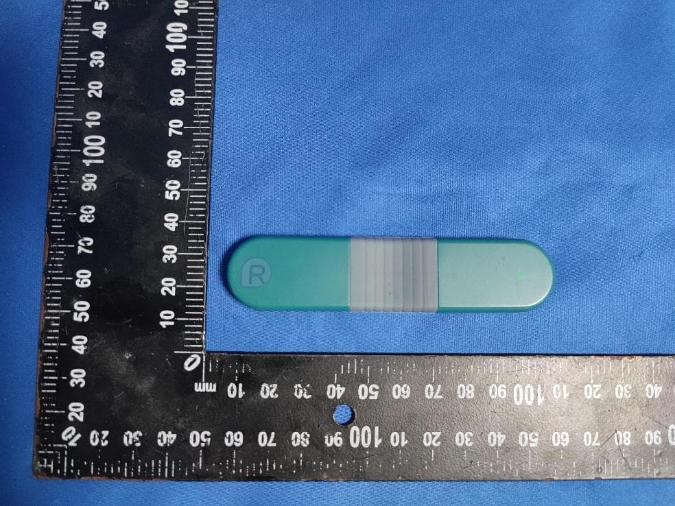
Click to zoom
Application Details
- Equipment Class
- DTS - Digital Transmission System
- Date of Grant
- Aug 14, 2022
- Application Purpose
- Original Equipment
- Date of Application
- Aug 14, 2022
- Equipment Note
- Personal ECG Tracker
- Frequency Range
- 2402.00000000 - 2480.00000000
- Country
- China
Documents & Files
Document Text
Text extracted from the exhibit documents filed with the FCC. Open a document above to read the original.
Users Manual
制作工艺: 80g书写纸;骑马钉,黑白印刷 尺寸: 95*142mm 此页不印刷 User Manual Personal ECG Tracker User Manual Contents 1. Introduction ........................................................ 1 2. Warnings ............................................................ 1 3. Packing List ........................................................ 4 4. Guide to Parts ................................................... 5 5. Activate the Device .......................................... 7 5.1. Charge the device ..................................... 7 5.2. Download software and sync time ........ 8 6. Record your ECG ............................................... 9 6.1. Wear the device ......................................... 9 6.2. Start recording......................................... 12 6.3. Stop recording ......................................... 12 7. View ECG Measurement Results .................. 13 8. Maintenance ................................................... 14 9. Troubleshooting .............................................. 15 10. Specifications ................................................ 16 11. Symbols ........................................................... 18 12. FCC Statement .............................................. 19 1 1. Introduction It is intended to record and store electrocardiogram (ECG) rhythms, and transfer records to the software for further research or analysis. It is not a medical device and should not be used for any medical purposes or any medical conditions. It is intended only for general wellness use. 2. Warnings The ECG results (including regular heartbeat) do not guarantee that you are free from an arrhythmia or other health conditions. You should notify your physician of possible changes of your health. Do not use the device to self-diagnose heart-related conditions. Consult with your physician before making any 2 medical decisions, such as altering your use of any drug or treatment. Do not continue to use the device until further instructed by a physician if your skin is irritated or inflamed around the electrodes. The device makes no warranty for any erroneously collected data or information from misuse or malfunction as a result of abuse, accidents, alteration, negligence, or failure to maintain the products as instructed. The results made by this device are preliminary screening of cardiac conditions, not a complete diagnosis. All interpretations should be reviewed by a medical professional for clinical decision-making. The device has not been tested for and is not intended for pediatric use. Keep the device away from young children. Contents may be harmful if swallowed. 3 Do not store in extremely hot, cold, humid, wet, or bright conditions. Do not take a recording if the electrodes are dirty. Clean them first. Do not immerse the device in or expose the device to excessive liquid. Do not drop or bump with excessive force. Do not expose to strong electromagnetic fields. Do not expose the device to a magnetic resonance (MR) environment. Do not use with a cardiac pacemaker, ICDs, or other implanted electronic devices. Do not use during cautery and external defibrillation procedures. Do not place the electrodes in contact with other conductive parts including the earth. 4 Do not use with unapproved accessories. The use of unapproved accessories or transducers and cables may result in electromagnetic emission or decreased electromagnetic immunity of this device which will further lead to improper operation. Do not use the device adjacent to or stacked with other equipment because it may result in improper operation. 3. Packing List Main unit A USB clip A USB drive with the software A pack of disposable electrodes (10 pieces) Chest strap 5 4. Guide to Parts Indicator Status Description / OFF Out of battery Green light On with high brightness Fully charged Orange light Charging LED indicator Power contact “R” symbol Electrode snap Electrode snap 6 Green light /Orange light (low battery) Flashing every 5 seconds with medium brightness In standby mode Flashing with medium brightness Downloading data On with low brightness Lead off On with low brightness and flashing with medium brightness when detecting R wave Recording your ECG 7 5. Activate the Device 5.1. Charge the device a) Connect the device with the USB clip, as shown below. b) Connect the other end of the clip to a power supply, like a laptop or power adapter. Note: The power adapter is not included in the package. Compatible power adapter output: DC 5V, 1A. Do not use the device while charging. 8 5.2. Download software and sync time a) Download the software For MacOS & Window: Visit the website www.livenpace.com/pages/download for free download. For macOS: Search for “Livenpace” in the App Store. For Windows: Find the accompanied USB drive and copy the installation file to your local drive for installation. b) Install the software. c) Connect the device to your PC or laptop with the power/data cable and run the software. It will automatically connect to the device and synchronize time. 9 Note: Failed time synchronization may result in wrong recording time. For more information on how to use the software, visit the website https://livenpace.com/pages/support or scan the QR code below. 6. Record your ECG 6.1. Wear the device Choose one of the following methods for recording ECG: 10 With electrodes a) Remove the body hair and moisturize the skin of the contact area. b) Attach the device to the disposable electrodes. c) Remove the protective film from the electrodes. d) Apply the device to the left chest. The “R” symbol is rightward and near the middle of sternal notch, and the other end is leftward and 45° lower than the horizontal level. 45° 11 With chest strap a) Attach the device to the chest strap. b) Moisturize the skin with water or water-based lotion on the contact area. c) Untie the strap and position the device across the front of the chest ju…
Text truncated - open the document above for the full version.
Cover Letter(s)
ShenzhenLivenpaceTechnologyCo.,Ltd. AgentAuthorization Company:ShenzhenLivenpaceTechnologyCo.,Ltd. Address:4F,BLD9,BaiwangxinIndustrialPark,SongbaiRoad,XiliStreet,Nanshan District,Shenzhen,China ProductName:PersonalECGTracker ModelNumber(s):HHM1 ProductDescription:PersonalECGTracker WeauthorizeMiCOMLabsInc.,575BoulderCourt,Pleasanton,California94566,USA, toactonourbehalfonallmattersconcerningthecertificationofabovenamed equipment. WedeclarethatMiCOMLabsInc.isallowedtoforwardallinformationrelatedtothe approvalandcertificationofequipmenttotheregulatoryagenciesasrequiredandto discussanyissuesconcerningtheapprovalapplication.Anyandallactscarriedoutby MiCOMLabsonourbehalfshallhavethesameeffectasactsofourown. Signature:Date:2022.08.10 Name:BingWang Title:Manager Company:ShenzhenLivenpaceTechnologyCo.,Ltd.
Cover Letter(s)
承 認 書 SPECIFICATION FOR APPROVAL 客戶名稱 CUSTOMER : 客戶料號 CUSTOMER’S P/N : 料號 PART NUMBER : WAN5010F245H05 規格 DESCRIPTION : Chip Antenna 5010 M-Ant 2.4~2.5G Type H05 版本 VERSION : V1.0 日期 ISSUE DATE : 2019/05/20 客 戶 承 認 CUSTOMER APPROVED 工 程 部 R&D CENTER 承 認 APPROVAL 確 認 CHECKED 製 作 DRAWN Ray James Thor 萬誠科技股份有限公司 OneWave Electronic Co., Ltd. 112台北市北投區立功街151號1樓 1F, No. 151, Li Gong Street, Beitou District, Taipei City 112, Taiwan 電話: (02) 2898-2220 TEL: +886 2 2898-2220 傳真: (02) 2898-5055 FAX: +886 2 2898-5055 2/11 ONEWAVE TECHNOLOGY CO., LTD. 5010 Chip antenna For Bluetooth / WLAN Applications Dimension (mm) L 5.01 ± 0.20 W 1.02 ± 0.20 T 1.25 ± 0.20 P/N: WAN5010F245H05 3/11 ONEWAVE TECHNOLOGY CO., LTD. Part Number Information WAN 5010 F 245 H 05 A B C D E F A Product Series Antenna B Dimension L x W 5.0X1.0mm (+-0.2mm) C Material High K material D Working Frequency 2.4 ~ 2.5GHz E Feeding mode Monopole & Single Feeding F Antenna type Type=05 1. Electrical Specification Remark : Bandwidth & Peak Gain was measured under evaluation board of next page Specification Part Number WAN5010F245H05 Central Frequency 2450 MHz Bandwidth 100 (Min.) MHz Return Loss -10 (Max) dB Peak Gain 3.12 dBi Impedance 50 Ohm Operating Temperature -40~+85 °C Maximum Power 4 W Resistance to Soldering Heats 10 ( @ 260°C) sec. Polarization Linear Azimuth Beamwidth Omni-directional Termination Cu / Sn (Leadless) 4/11 ONEWAVE TECHNOLOGY CO., LTD. 2. Recommended PCB Pattern Evaluation Board Dimension Unit : mm Suggested Matching Circuit 重要資訊 : 匹配元件建議使用精準度高的電感±0.1~0.3nH、電容±0.1pF 5/11 ONEWAVE TECHNOLOGY CO., LTD. Layout Dimensions in Clearance area( Size=7.0*5.0mm) 50 ohm transmission Line Matching Circuit Layout Dimensions in Clearance area( Size=7.0*3.0mm) 50 ohm transmission Line Matching Circuit FootPrint (Unit : mm) 6/11 ONEWAVE TECHNOLOGY CO., LTD. 3. Measurement Results Return Loss 7/11 ONEWAVE TECHNOLOGY CO., LTD. Radiation Pattern Efficiency Peak Gain Directivity 2400MHz 59.12 % 2.45 dBi 5.38 dBi 2450MHz 70.02 % 3.12 dBi 5.25 dBi 2500MHz 63.68 % 2.71 dBi 5.32 dBi Chamber Coordinate System Y Z X 8/11 ONEWAVE TECHNOLOGY CO., LTD. 4.Reliability and Test Condictions ITEM REQUIREMENTS TEST CONDITION Solderability 1. Wetting shall exceed 90% coverage 2. No visible mechanical damage Pre-heating temperature:150°C/60sec. Solder temperature:230±5°C Duration:4±1sec. Solder:Sn-Ag3.0-Cu0.5 Flux for lead free: rosin Solder heat Resistance 1. No visible mechanical damage 2. Central Freq. change :within ± 6% 10±0.5 sec. 60sec .. TEMP (°C) 150°C 260°C Pre-heating temperature:150°C/60sec. Solder temperature:260±5°C Duration:10±0.5sec. Solder:Sn-Ag3.0-Cu0.5 Flux for lead free: rosin Component Adhesion (Push test) 1. No visible mechanical damage The device should be reflow soldered(230 ±5°C for 10sec.) to a tinned copper substrate A dynometer force gauge should be applied the side of the component. The device must with-ST-F 0.5 Kg without failure of the termination attached to component. Component Adhesion (Pull test) 1. No visible mechanical damage Insert 10cm wire into the remaining open eye bend ,the ends of even wire lengths upward and wind together. Terminal shall not be remarkably damaged. Thermal shock 1. No visible mechanical damage 2. Central Freq. change :within ±6% Phase Temperature(°C) Time(min) 1 +85±5°C 30±3 2 Room Temperature Within 3sec 3 -40±2°C 30±3 4 Room Temperature Within 3sec +85°C=>30±3min -40°C=>30±3min Test cycle:10 cycles The chip shall be stabilized at normal condition for 2~3 hours before measuring. Resistance to High Temperature 1. No visible mechanical damage 2. Central Freq. change :within ±6% 3. No disconnection or short circuit. Temperature: 85±5°C Duration: 1000±12hrs The chip shall be stabilized at normal condition for 2~3 hours before measuring. Resistance to Low Temperature 1. No visible mechanical damage 2. Central Freq. change :within ±6% 3. No disconnection or short circuit. Temperature:-40±5°C Duration: 1000±12hrs The chip shall be stabilized at normal condition for 2~3 hours before measuring. Humidity 1. No visible mechanical damage 2. Central Freq. change :within ±6% 3. No disconnection or short circuit. Temperature: 40±2°C Humidity: 90% to 95% RH Duration: 1000±12hrs The chip shall be stabilized at normal condition for 2~3 hours before measuring. 4±1 sec. 60sec TEMP (°C) 150°C 230°C 9/11 ONEWAVE TECHNOLOGY CO., LTD. 5.Soldering and Mounting Mildly activated rosin fluxes are preferred. The minimum amount of solder can lead to damage from the stresses caused by the difference in coefficients of expansion between solder, chip and substrate. The terminations are suitable for all wave and re-flow soldering systems. If hand soldering cannot be avoided, the preferred technique is the utilization of hot air soldering tools. Recommended temperature profiles for re-flow soldering in Figure 1. Products attachment with a soldering iron is discouraged due to the inherent process control limitations. In the event that a soldering iron must be employed the following precautions are recommended. ‧Preheat circuit and products to 150°C ‧Never contact the ceramic with the iron tip ‧Use a 20 watt soldering iron with tip diameter of 1.0mm ‧280°C tip temperature (max) ‧1.0mm tip diameter (max) ‧Limit soldering time to 3 sec. SOLDERING COOLING NATURAL PRE-HEATING TEMPERATURE(°C) 60~120 s 10s max. 30~60s 250~260 230 180 150 TIME(sec.) Reflow Soldering SOLDERING COOLING NATURAL PRE-HEATING TEMPERATURE(°C) within 3s Gradualcooling 150 TIME(sec.) Iron Soldering Over 60s 350 300 10/11 ONEWAVE TECHNOLOGY CO., LTD. 6.Packaging Information Tape Specification: W Ao Bo Ko P F E D D1 Po P2 t 16.0 ±0.30 1.30 ±0.10 5.30 ±0.10 1.50 ±0.10 4.00 ±0.10 7.50 ±0.10 1.75 ±0.10 1.50 ±0.10 0.00 ±0.10 4.00 ±0.10 2.00 ±0.10 0.30 ±0.05 Reel Specification: (7’’, Φ180 mm) Tape Width(mm) A(mm) B(mm) C(mm) D(mm) Chip/Reel(pcs) 16 16±1.0 60±2 13.5±0.5 178±2 3000 11/11 ONEWAVE TECHNOLOGY CO., LTD. 7.Storage and Transportation Information Storage…
Text truncated - open the document above for the full version.
Cover Letter(s)
ShenzhenLivenpaceTechnologyCo.,Ltd. OfficeofEngineeringTechnology FederalCommunicationsCommission 7435OaklandMillsRoad Columbia,MD21046 USA Date:2022.08.10 Subject;RequestforConfidentiality FCCID:2A728-0001 ToWhomItMayConcern, PursuanttotheprovisionsoftheCommission’srulesTitle47Sections§0.457and§0.459,we arerequestingtheCommissiontowithholdthefollowingattachment(s)asconfidential documentsfrompublicdisclosureindefinitely. Thesedocumentscontaindetailedsystemandequipmentdescriptionsandareconsideredas proprietaryinformationinoperationoftheequipment.Thepublicdisclosureofthesedocuments mightbeharmfultoourcompanyandwouldgivecompetitorsanunfairadvantageinthemarket. SchematicDiagram BlockDiagram PartsList OperationalDescription Tune-upProcedure Inadditionaltoabovementioneddocuments,inordertocomplywiththemarketingregulations inTitle47CFR§2.803andtheimportationrulesinTitle47CFR§2.1204,whileensuringthat businesssensitiveinformationremainsconfidentialuntiltheactualmarketingofnewly authorizeddevices,werequestShortTermConfidentialityofthefollowingattachment(s); ExternalPhotos TestSetupPhotos InternalPhotos UserManual For45days,pursuanttoPublicNoticeDA04-1705. OR For180dayspursuanttoKDB726920D01. Itisourunderstandingthatallmeasurementtestreports,FCCIDlabelformatand correspondenceduringthecertificationreviewprocesscannotbegrantedasconfidential documentsandthisinformationwillbeavailableforpublicreviewoncethegrantofequipment authorizationisissued. Sincerely, Signature: Name:BingWang Title:Manager
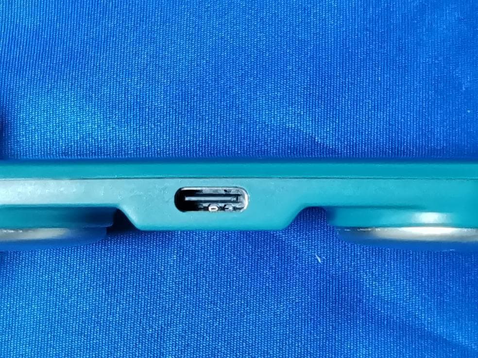
External Photos
EUTPHOTOS(ExternalPhotos)
ID Label/Location Info
1 NAMEDATE D ESIGN CHECKED APPROVED SCALE:1:1 3 214 5678 3 214 5678 B A C D E F G H B A C D E F G H REVDESIGNDATEAPPROVED PART NO.: ART-210-05315-01 UNIT:MM MATERIAL: SIZE: A4SHEET 1 OF 1 REV.A PROJECTION HHM1-左下壳打标图 SN: 2207490001 Not intended for infants weighing less than 10KgProduction Data: 2022-07 FCC ID: 2A728-0001Made in china HHM1左下壳(Livenpace版)-已打标 TITLE: DESCRIPTION NAMEDATE D ESIGN CHECKED APPROVED SCALE:1:1 3 214 5678 3 214 5678 B A C D E F G H B A C D E F G H REVDESIGNDATEAPPROVED PART NO.: ART-210-05314-00 UNIT:MM MATERIAL: SIZE: A4SHEET 1 OF 1 REV.A PROJECTION HHM1-右下壳(Livenpace)-已打标 HHM1右下壳(Livenpace)-已打标 TITLE: Manufacture﹕ Shenzhen Livenpace Technology Co., Ltd. Input: DC 5V, 1A Internal power: 3.7V /90mAh Li-ion rechargeable Personal ECG Tracker Model: HHM1 DESCRIPTION
Internal Photos
EUTPHOTO(InternalPhotos) ANT ※※※※※ENDOFREPORT※※※※※
RF Exposure Info
FCCID:2A728-0001 RFExposureEvaluation AccordingtoKDB447498D01GeneralRFExposureGuidancev06andpart2.1093 , UnlessspecificallyrequiredbythepublishedRFexposureKDBprocedures,standalone 1-gheadorbodyand10-gextremitySARevaluationforgeneralpopulationexposure conditions,bymeasurementornumericalsimulation,isnotrequiredwhenthe correspondingSARTestExclusionThresholdcondition(s),listedbelow,is(are)satisfied. For100MHzto6GHzandtestseparationdistances≤50mm,the1-gand10-gSARtest exclusionthresholdsaredeterminedbythefollowing: [(max.powerofchannel,includingtune-uptolerance,mW)/(min.testseparationdistance, mm)]·[√f (GHz) ]≤3.0for1-gSAR,and≤7.5for10-gextremitySAR,where f (GHz) istheRFchanneltransmitfrequencyinGHz PoweranddistanceareroundedtothenearestmWandmmbeforecalculation Theresultisroundedtoonedecimalplaceforcomparison Here, ForBluetooth Mode Max Power (dBm) Tune-up power (dBm) Max Power (mW) Frequency(MHz) Min. Distance (mm) Calc. thresholds limit BLE-0.220 ± 11.26244050.39343.0 SoaSARtestisnotrequired
Test Report
ProjectNo.:ZKT-220729L5313E Page 1 of 39 FCCTESTREPORT FCCID:2A728-0001 ReportNumber.....................................:ZKT-220729L5313E DateofTest ....................................................... : Jul.25,2022toAug.07,2022 Dateofissue ......................................... : Aug.07,2022 Totalnumberofpages..........................39 TestResult .......................................... : PASS TestingLaboratory. .............................. : ShenzhenZKTTechnologyCo.,Ltd. Address...............................................: 1/F,No.101,BuildingB,No.6,TangweiCommunityIndustrial Avenue,FuhaiStreet,Bao'anDistrict,Shenzhen,China Applicant'sname................................:ShenzhenLivenpaceTechnologyCo.,Ltd. Address ............................................... : 4F,BLD9,BaiwangxinIndustrialPark,SongbaiRoad,XiliStreet, NanshanDistrict,Shenzhen,China Manufacturer'sname.........................:ShenzhenLivenpaceTechnologyCo.,Ltd. Address...............................................: 4F,BLD9,BaiwangxinIndustrialPark,SongbaiRoad,XiliStreet, NanshanDistrict,Shenzhen,China Testspecification: Standard................................................:FCCCFRTitle47Part15SubpartCSection15.247 Testprocedure.....................................:KDB558074D0115.247MeasGuidancev05r02 ANSIC63.10:2013 Testprocedure.....................................:KDB558074D0115.247MeasGuidancev05r02 ANSIC63.10:2013 Non-standardtestmethod ................ :N/A TestReportFormNo. ....................... : TRF-EL-111_V0 TestReportForm(s)Originator.....: ZKTTesting MasterTRF........................................: Dated:2020-01-06 ThisdevicedescribedabovehasbeentestedbyZKT,andthetestresultsshowthattheequipmentunder test(EUT)isincompliancewiththeFCCrequirements.Anditisapplicableonlytothetestedsample identifiedinthereport. Thisreportshallnotbereproducedexceptinfull,withoutthewrittenapprovalofZKT,thisdocumentmay bealteredorrevisedbyZKT,personalonly,andshallbenotedintherevisionofthedocument. Productname.......................................:PersonalECGTracker Trademark...........................................: Model/Typereference ......................... : HHM1 Ratings .................................................. : Input:5V1AorDC3.7V,90mAh,0.333Whbybattery ProjectNo.:ZKT-220729L5313E Page 2 of 39 Testingprocedureandtestinglocation: TestingLaboratory.......................................:ShenzhenZKTTechnologyCo.,Ltd. Address............................................................:1/F,No.101,BuildingB,No.6,TangweiCommunity IndustrialAvenue,FuhaiStreet,Bao'anDistrict, Shenzhen,China JimLiu Testedby(name+signature).......................: TomZou Reviewer(name+signature).......................: LakeXie Approved(name+signature).......................: ProjectNo.:ZKT-220729L5313E Page 3 of 39 TableofContents Page 1.VERSION....................................................................................................................5 2.SUMMARYOFTESTRESULTS...............................................................................6 2.1TESTFACILITY.................................................................................................................7 2.2MEASUREMENTUNCERTAINTY....................................................................................7 3.GENERALINFORMATION........................................................................................8 3.1GENERALDESCRIPTIONOFEUT.................................................................................8 3.2DESCRIPTIONOFTESTMODES....................................................................................9 3.3BLOCKDIGRAMSHOWINGTHECONFIGURATIONOFSYSTEMTESTED..............9 3.4DESCRIPTIONOFSUPPORTUNITS(CONDUCTEDMODE)......................................10 3.5EQUIPMENTSLISTFORALLTESTITEMS.................................................................11 4.EMCEMISSIONTEST.............................................................................................12 4.1CONDUCTEDEMISSIONMEASUREMENT..................................................................12 4.1.1POWERLINECONDUCTEDEMISSIONLimits...................................................12 4.1.2TESTPROCEDURE...............................................................................................12 4.1.3DEVIATIONFROMTESTSTANDARD..................................................................12 4.1.4TESTSETUP...........................................................................................................13 4.1.5EUTOPERATINGCONDITIONS...........................................................................13 4.1.6TESTRESULTS......................................................................................................14 4.2RADIATEDEMISSIONMEASUREMENT......................................................................16 4.2.1RADIATEDEMISSIONLIMITS...............................................................................16 4.2.2TESTPROCEDURE...............................................................................................17 4.2.3DEVIATIONFROMTESTSTANDARD..................................................................17 4.2.4TESTSETUP...........................................................................................................17 4.2.5EUTOPERATINGCONDITIONS...........................................................................18 5.RADIATEDBANDEMISSIONMEASUREMENT.....................................................23 5.1TESTREQUIREMENT:..............................................................................................23 5.2TESTPROCEDURE..................................................................................................23 5.3DEVIATIONFROMTESTSTANDARD.....................................................................23 5.4TESTSETUP..............................................................................................................24 5.5EUTOPERATINGCONDITI…
Text truncated - open the document above for the full version.
Test Setup Photos
EUTTESTPHOTOS ※※※※※ENDOFREPORT※※※※※
Contact Information
Applicant
Bing Wang(Manager)
Technical Contact
Test Firm
Shenzhen ZKT Technology Co., Ltd.Lake Xie
[email protected]0086-13620010775
Technical Specifications
| # | Rule Parts | Frequency Range | Power Output |
|---|---|---|---|
| 1 | 15C | 2.40 GHz - 2.48 GHz | 950.00 µW |
Other Applications from Shenzhen Livenpace Technology Co., Ltd.
2A728-0003
Aug 14, 2022Personal ECG Monitor
Equipment Class
DTS - Digital Transmission System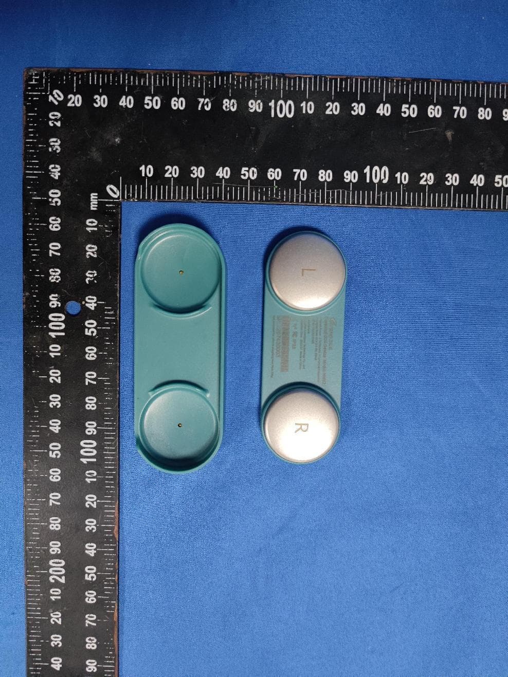
2A728-0002
Aug 14, 2022Personal ECG Device
Equipment Class
DTS - Digital Transmission System