FCCID.CO- FCC ID Database
HomeCompaniesEquipment ClassesSearch

© 2026 FCC ID Database. All rights reserved.

AboutContactData sourced from FCC public records
  1. Home/
  2. arpara Technology Co.,Ltd/
  3. 2A77G-VRM1020

2A77G-VRM1020arpara AIO 5K

arpara Technology Co.,Ltd
arpara AIO 5K - FCC ID 2A77G-VRM1020 - arpara Technology Co.,Ltd
Click to zoom

Application Details

Equipment Class
DTS - Digital Transmission System
Date of Grant
Nov 11, 2022
Application Purpose
Original Equipment
Date of Application
Nov 11, 2022
Equipment Note
arpara AIO 5K
Frequency Range
2412.00000000 - 2462.00000000
Company
arpara Technology Co.,Ltd
Country
China

Documents & Files

Select a file to view
Users Manual

↗

Cover Letter(s)

↗
↗
↗
↗

External Photos

ID Label/Location Info

Internal Photos

↗

RF Exposure Info

↗
↗
↗
↗

Test Report

↗
↗
↗
↗
↗

Test Setup Photos

↗
↗

Document Text

Text extracted from the exhibit documents filed with the FCC. Open a document above to read the original.

Users Manual

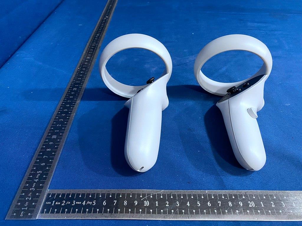
User Guide 说明书 說明書 매뉴얼 English Version 04-28 繁体中文版 52-75 简体中文版29-51 日本語版 76-98 한국어�버전 99-121 01 arpara VR 助手 中国大陆地区 China Mainland 安卓 https://www.arpara.net/supports/downloads iOS Regions and countries outside China Mainland arpara VR Assistant 02 关注公众号 @arpara Global 用户可以到官网查询产品操作指南以及产品教学视频: www.arpara.net (China Mainland) Users may go to Official Websites for detailed instruction guide and tutorial video: www.arparaland.com (Regions and Countries Outside China Mainland) 03 User Guide 04 arpara AIO 5K VR Headset *1arpara AIO Controller * 2 User Manual * 1 User Manual arpara AIO 5K Carrying Case * 1 Notes: 1. Users need to purchase four 1.5V AA batteries 2. A power adapter is provided for free 3. A charging cable ( USB Type-C 3.2) is provided for free Package Content 05 Power Button USB-C 3.0 Port Camera * 4 06 Instruction of VR Headset Buttons and Light Indicator Light Indicator The Meaning of Light Indicator: White Solid: Screen is on, >20% remaining Red Solid: Screen is on, <20% remaining White Blinking: Turning on, >20% remaining Red Blinking: Turning on, <20% remaining No light: Hibernated, Turned off Yellow Blinking : Battery is charging, < 20% remaining Green Blinking : Battery is charging, >20% remaining Green Solid : Battery is charged Notes: The standard of power adapter: 1. Standard of power adapter: Input: AC100-240V 50/60Hz 0.6 Output: 5V-3A, 9V-2.22A-1.67A(MAX) Total Output: 20W (MAX) 2. Users who live in Mainland China, or whose Electricity Voltage (AC100-240V) is the same as Mainland China do not need to pur- chase an extra outlet plug adapter. 3. arpara does not sell or provide outlet plug adapters to users 07 Volume Button Top Strap Slot Directional Speakers Noise-canceling Mic Noise-canceling Mic 3.5 mm Audio Jack Instruction of VR Headset Buttons and Light Indicator arpara AIO 5K Facial Foam (Non-removable) Heat Vent IPD Adjustment Wheel arpara AIO 5K Elite Mask (Removable) 08 ProximitySensor Diopter Knob Top Strap Hole arpara AIO 5K Elite Strap built-in Battery (Non- removable) Support Foam Top Strap Optical Lens Instruction of VR Headset Buttons and Light Indicator arpara AIO 5K Elite Strap Knob 09 1 2 3 4 8 5 9 10 6 7 X/Y Button 2 Menu Button 3 A/B Button 4 Grip Button 5 Battery cover 6 Home Button 7 Wrist Strap 8 Trigger 9 Light Indicator 10 Left Controller Right Controller Tracking Aura Instruction of Controllers and Light Indi- cator 1 Thumbtick 10 Quick Start 1. Install batteries 11 Quick Start 2. Press and hold [Power Button] for 2s to turn the power on. The light turns white. Power Button 12 Quick Start 3. Diopter Adjustment The range of diopter adjustment: -5D~1D. Rotate [Diopter Knob] clockwise or counterclockwise for each eye until you see clear images. 1 0 1 2 3 4 5 1 0 1 2 3 4 5 1 0 1 2 3 4 5 1 0 1 2 3 4 5 13 Quick Start 4.Wear the Headset Adjust [arpara AIO 5K Elite Strap Knob] clockwise or counterclockwise to your head circumference to make sure the VR headset fits comfortably. Then fix the sticker on [Top Strap]. (It is recommended to tilt [arpara AIO 5K Elite Strap ] to 15°) 15° Turn the knob 14 5.IPD Adjustment Adjust your interpupillary distance by sliding [IPD Adjustment Wheel] on top of the headset. Quick Start 15 Maintenance 16 Please use a soft cloth to clean the lens. Do not use any liquid or chemical cleaner to clean the lens. (Do not use alcohol to clean the lens, as it will cause lens aging.) Use a disinfectant wet towel or microfiber dry cloth dipped in small amount of 75% alcohol to gently wipe [arpara AIO 5K Elite Mask] and dry it naturally. (Avoid direct exposure to sunlight.) Use a disinfectant wet towel or microfiber dry cloth dipped in small amount of 75% alcohol to gently wipe the product surface and dry it naturally. Avoid water ingress when cleaning it To avoid damage to screens, do not expose the lens to direct sunlight Do not direct the lens with laser or external light source Please keep controllers' [Battery Cover] locked. Please keep the batteries out of the reach of children Avoid extreme temperature or contact with water, liquids, excessive moisture and naked fire Store the headset in arpara AIO 5K Carrying Case when not in use to reduce accidental damage or exposure to extreme environmental conditions 17 Handle with care to prevent falling. Do not scratch the lens with sharp objects Only use hardware, accessories, software and content recommended by arpara Operating temperature: 0-45°C /32-113°F, minimum humidity: 5%, maximum humidity: relative humidity of 95% (non-condensing.) Non-operating temperature (storage): -20-45°C / -4-113°F, relative humidity of 85% 18 Cautions 19 Before using arpara AIO 5K, verify the safety of your surroundings to avoid injury. 1. Define and set-up a safe play area 2. We recommend indoor use only for safety purposes 3. Clear a safe play area before wearing arpara AIO 5K to avoid tripping or bumping injuries. Play Area Set-up 20 Health and Safety Warnings Please read and follow this manual along with product settings and instructions provided on the official website Read and follow arpara AIO 5K hardware and software recommendations. Failing to use the recommended hardware and software may increase the risk of physical discomfort Do not use any unrecognized hardware or software. The use of unrecognized hardware or software may cause harm to you and lead to equipment or system operation problems Please ensure that you are physically comfortable when using arpara AIO 5K. Do not use arpara AIO 5K after drinking or taking medicines, feel tired or sleep-deprived, under emotional pressure, after hangover or digestive problem, suffer from cold, headache or earache. Otherwise, you may feel discomfort *arpara will update product Health and Safety Warnings on regular basis to ensure accuracy and completeness. Please carefully read all the following warnings to reduce personal injury, discomfort or property loss. Warnings before Use 21 Convulsive symptoms are more common among children and people under 20 …

Text truncated - open the document above for the full version.

Cover Letter(s)

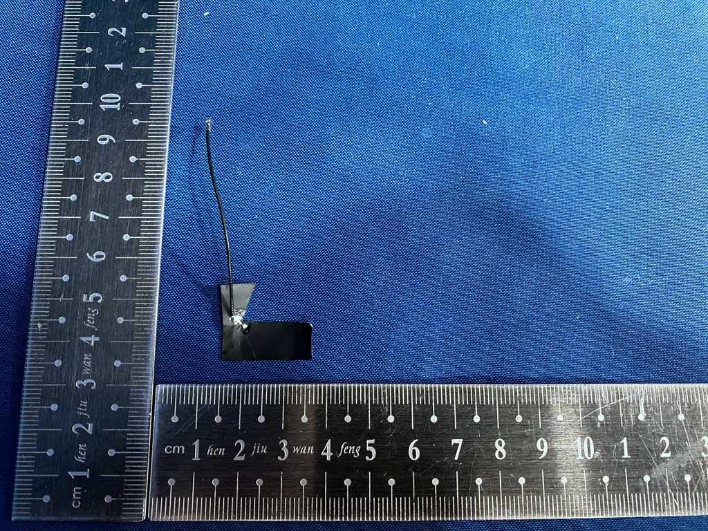
昆山科睿谛电子科技有限公司 规 格 书 SPECIFICATION FOR APPROVAL 客户名称 Customer: 产品名称 Product Name: 规格描述 Description: 客户料号 CUSTP/N: 料号 P/N: 发出日期 Approval Date: 核准 Approved 审核 Checked By 制作 Made By 杜晓艳 客户承认 Customer Approve 核准 Approved 审核 Checked By 承办 Undertake By 地 址:江苏省昆山市张浦镇俱进路8号 电 话:+86 512-55178611 传 真:+86 512-55178611 E-MAIL: [email protected] 网 址:http://www.credit-krd.com 2.4 5G内置天线,L=50mm;黑色 2022年03月28日 WIFI02 Antenna 郭姝洁 KRDC-WIFI02050ZS4 ~ 2 ~ 目录 No. 承认书内容 页面 备注 1 封面 1-1 2 目录 2-2 3 承认书变更履历表 3-3 4 CABLE SPEC& CONNECTOR SPEC 4-5 5 工程图 6-6 6 测试报告 7-9 ~ 3 ~ 承认书变更履历表 No. 原版 变更日期 变更内容 变更项目描述 1 A 2022-01-21 新增 --------------- 2 B 2022-03-28 变更尺寸 测试数据 ~ 4 ~ 线材端子规格书 ~ 5 ~ ~ 6 ~ ~ 7 ~ Frequency Gain (dBi) 2.4GHz 1.43 2.412GHz 1.99 2.442GHz 1.71 2.45GHz 1.57 2.472GHz 2.15 2.5GHz 1.98 Frequency Gain (dBi) 5.15GHz 0.74 5.25GHz 1.46 5.35GHz 2.55 5.45GHz 2.98 5.47GHz 1.72 5.55GHz 3.6 5.6GHz 4.25 5.7GHz 4.94 5.725GHz 4.46 5.75GHz 4.49 5.775GHz 4.23 5.785GHz 4.18 5.8GHz 4.14 5.825GHz 3.77 5.85GHz 4.1 ~ 8 ~ 测试报告 ~ 9 ~

Cover Letter(s)

arpara Technology Co.,Ltd Room 109 1/F Building 36, Nantaihu Dongyuan Business BuildingHigh-tech Zone, Wuxing District, Huzhou, China DATE : 2022/09/07 arpara Technology Co.,Ltd Room 109 1/F Building 36, Nantaihu Dongyuan Business BuildingHigh-tech Zone, Wuxing District, Huzhou, China Attn: Director of Certification Authority to Act as Agent On our behalf, I appoint below company and person: Name Damon Hu Position Manager Company Name Dongguan Dongdian Testing Service Co.,Ltd. Address 17, Zongbu Road 2, Songshan Lake Sci&Tech, Industry Park, Dongguan City, Guangdong Province, China, 523808 Tel / Fax Tel: +86-0769-38826678-850 E-Mail [email protected] to act as our agent in the preparation of this application for equipment certification. I certify that submitted documents properly describe the device or system for which equipment certification is sought. I also certify that each unit manufactured, imported or marketed, as defined in the Federal Communications Commission’s regulations will have affixed to it a label identical to that submitted for approval with this application. For instances where our authorized agent signs the application for certification on our behalf, I acknowledge that all responsibility for complying with the terms and conditions for certification, as specified by CETECOM GmbH, still resides with: Applicant name arpara Technology Co.,Ltd Address Room 109 1/F Building 36, Nantaihu Dongyuan Business BuildingHigh-tech Zone, Wuxing District, Huzhou, China Yours sincerely, Name Andrey Liu Position Quality Director Company Name arpara Technology Co.,Ltd Address Room 109 1/F Building 36, Nantaihu Dongyuan Business BuildingHigh-tech Zone, Wuxing District, Huzhou, China Tel / Fax 0572-2076367 E-Mail [email protected]

Cover Letter(s)

CONFIDENTIALITY REQUEST for Certification Service in USA Federal Communication Commission Equipment Authorization Division, Application Processing Branch 7435 Oakland Mills Road Columbia, MD 21048 <09/07/2022> TO WHOM IT MAY CONCERN Pursuant to Paragraphs §0.457 and 0.459 of the Commission’s Rules (47 C.F.R.) and Section §552(b) (4) of the Freedom of Information Act, we request confidentiality for the following products: FCC ID: 2A77G-VRM1020 Model name: VRM1020WNA For the product stated above, we request that the following information be held confidential; Exhibits Long-Term Confidentiality Short-Term Confidentiality Short-Term Confidentiality Days External Photos 180 days Internal Photos 180 days Block Diagram Schematics Test Setup Photos 180 days User’s Manual 180 days Parts List Tune Up Operational Descriptions The long-term confidentiality exhibits contain our trade secrets and proprietary information that could be of benefit to our competitors. The short-term confidentiality on the basis of ensuring that business sensitive information remains confidential until the actual marketing of our new device. If you have any questions, please feel free to contact me at the address shown below. Sincerely, Name: Andrey Liu Company: arpara Technology Co.,Ltd Address: Room 109 1/F Building 36, Nantaihu Dongyuan Business BuildingHigh-tech Zone, Wuxing District, Huzhou, China Phone: 0572-2076367 E-Mail: [email protected]

Cover Letter(s)

arpara Technology Co.,Ltd Room 109 1/F Building 36, Nantaihu Dongyuan Business BuildingHigh-tech Zone, Wuxing District, Huzhou, China Date: 2022-09-07 FCC ID: 2A77G-VRM1020 Model Number: VRM1020WNA To: Federal Communications Commission Authorization and Evaluation Division 7435 Oakland Mills Road Columbia, MD To Whom It May Concern, We, arpara Technology Co.,Ltd declare that this EUT (FCC ID: 2A77G-VRM1020) doesn’t have Ad Hoc mode function on “on-US/Canada frequencies”. In addition. The frequency selection feature is disabled by firmware for devices marked to the US/Canada. For DTS part of this device, only channels 1-11 will be used in North America, Country code selection is disabled. Should you have any questions or comments regarding this matter, please have my best attention. Sincerely, Name / Title: Andrey Liu / Quality Director Company: arpara Technology Co.,Ltd Address: Room 109 1/F Building 36, Nantaihu Dongyuan Business BuildingHigh-tech Zone, Wuxing District, Huzhou, China Tel: 0572-2076367 E-Mail: [email protected]

Internal Photos

Dongguan Dongdian Testing Service Co., Ltd. Report No.: DDT-R22041329-2E01 Page 96 of 108 Dongguan Dongdian Testing Service Co., Ltd. Report No.: DDT-R22041329-2E01 Page 97 of 108 Dongguan Dongdian Testing Service Co., Ltd. Report No.: DDT-R22041329-2E01 Page 98 of 108 Dongguan Dongdian Testing Service Co., Ltd. Report No.: DDT-R22041329-2E01 Page 99 of 108 Dongguan Dongdian Testing Service Co., Ltd. Report No.: DDT-R22041329-2E01 Page 100 of 108 Dongguan Dongdian Testing Service Co., Ltd. Report No.: DDT-R22041329-2E01 Page 101 of 108 ANT1: BT/2.4G WIFI/5G WIFI Dongguan Dongdian Testing Service Co., Ltd. Report No.: DDT-R22041329-2E01 Page 102 of 108 ANT2: 2.4G WIFI/5G WIFI ANT3: RX ANT. Dongguan Dongdian Testing Service Co., Ltd. Report No.: DDT-R22041329-2E01 Page 103 of 108 Dongguan Dongdian Testing Service Co., Ltd. Report No.: DDT-R22041329-2E01 Page 104 of 108 Dongguan Dongdian Testing Service Co., Ltd. Report No.: DDT-R22041329-2E01 Page 105 of 108 Dongguan Dongdian Testing Service Co., Ltd. Report No.: DDT-R22041329-2E01 Page 106 of 108 Dongguan Dongdian Testing Service Co., Ltd. Report No.: DDT-R22041329-2E01 Page 107 of 108 Dongguan Dongdian Testing Service Co., Ltd. Report No.: DDT-R22041329-2E01 Page 108 of 108 END OF REPORT

Test Report

Dongguan Dongdian Testing Service Co., Ltd. Report No.: DDT-R22041329-2E03 Page 1 of 183 FCC CERTIFICATION TEST REPORT FOR Issued By: Dongguan Dongdian Testing Service Co., Ltd. Add.: No. 17, Zongbu Road 2, Songshan Lake Sci&Tech, Industry Park, Dongguan City, Guangdong Province, China, 523808 Tel.: +86-0769-38826678, E-mail: [email protected], http://www.dgddt.com Applicant : arpara Technology Co.,Ltd. Address : Room 109 1/F Building 36, Nantaihu Dongyuan Business Building High-tech Zone, Wuxing District, Huzhou City, Zhejiang Province China Equipment under Test : arpara AIO 5K Model No. : VRM1020WNA Trade Mark : FCC ID : 2A77G-VRM1020 Manufacturer : arpara Technology Co.,Ltd. Address : Room 109 1/F Building 36, Nantaihu Dongyuan Business Building High-tech Zone, Wuxing District, Huzhou City, Zhejiang Province China Report No.: DDT-R22041329-2E03 Issued Date: Aug. 31, 2022 Dongguan Dongdian Testing Service Co., Ltd. Report No.: DDT-R22041329-2E03 Page 2 of 183 Table of Contents Test report declares.......................................................................................................4 1. Summary of Test Results ............................................................................................... 6 2. General Test Information ............................................................................................... 7 2.1. Description of EUT ......................................................................................................... 7 2.2. Accessories of EUT ........................................................................................................ 8 2.3. Assistant equipment used for test .................................................................................. 8 2.4. Block diagram of EUT configuration for test .................................................................. 8 2.5. Deviations of test standard............................................................................................. 9 2.6. Test environment conditions .......................................................................................... 9 2.7. Test laboratory ............................................................................................................... 9 2.8. Measurement uncertainty ............................................................................................. 10 3. Equipment Used During Test ....................................................................................... 11 4. 6dB Bandwidth and 99% Bandwidth ............................................................................ 12 4.1. Block diagram of test setup .......................................................................................... 12 4.2. Limits ............................................................................................................................ 12 4.3. Test procedure ............................................................................................................. 12 4.4. Test result ..................................................................................................................... 13 4.5. Original test data .......................................................................................................... 15 5. Conducted Peak Output Power ................................................................................... 40 5.1. Block diagram of test setup .......................................................................................... 40 5.2. Limits ............................................................................................................................ 40 5.3. Test procedure ............................................................................................................. 40 5.4. Test result ..................................................................................................................... 40 6. Power Spectral Density ................................................................................................ 42 6.1. Block diagram of test setup .......................................................................................... 42 6.2. Limits ............................................................................................................................ 42 6.3. Test procedure ............................................................................................................. 42 6.4. Test result ..................................................................................................................... 42 6.5. Original test data .......................................................................................................... 44 7. Band Edge Compliance (Conducted Method) ............................................................. 57 7.1. Block diagram of test setup .......................................................................................... 57 7.2. Limits ............................................................................................................................ 57 7.3. Test procedure ............................................................................................................. 57 7.4. Test result ..................................................................................................................... 58 7.5. Original test data .......................................................................................................... 58 8. Radiated Spurious Emissions ...................................................................................... 67 8.1. Block diagram of test setup .......................................................................................... 67 Dongguan Dongdian Testing Service Co., Ltd. Report No.: DDT-R22041329-2E03 Page 3 of 183 8.2. Limit ............................................................................................................................…

Text truncated - open the document above for the full version.

Test Report

Dongguan Dongdian Testing Service Co., Ltd. Report No.: DDT-R22041329-2E03 Page 37 of 183 11AX20MIMO_Ant2_2462 11AX40MIMO_Ant1_2422 11AX40MIMO_Ant2_2422 Dongguan Dongdian Testing Service Co., Ltd. Report No.: DDT-R22041329-2E03 Page 38 of 183 11AX40MIMO_Ant1_2437 11AX40MIMO_Ant2_2437 11AX40MIMO_Ant1_2452 Dongguan Dongdian Testing Service Co., Ltd. Report No.: DDT-R22041329-2E03 Page 39 of 183 11AX40MIMO_Ant2_2452 Dongguan Dongdian Testing Service Co., Ltd. Report No.: DDT-R22041329-2E03 Page 40 of 183 5. Conducted Peak Output Power 5.1. Block diagram of test setup Same as section 4.1 5.2. Limits For systems using digital modulation in the 902-928 MHz, 2400-2483.5 MHz, and 5725-5850 MHz bands: 1 Watt. If transmitting antennas of directional gain greater than 6 dBi are used, the conducted output power from the intentional radiator shall be reduced below the stated values as appropriate, by the amount in dB that the directional gain of the antenna exceeds 6 dBi. 5.3. Test procedure Connect each EUT’s antenna output to power sensor by RF cable and attenuator Measure the PK output power of each antenna port by power meter. 5.4. Test result Test Mode Test Channel Ant Conducted Output Power (dBm) Limit [dBm] Verdict 11B 2412 ANT1 13.86 30 Pass 11B 2412 ANT2 14.18 30 Pass 11B 2437 ANT1 12.87 30 Pass 11B 2437 ANT2 13.60 30 Pass 11B 2462 ANT1 13.37 30 Pass 11B 2462 ANT2 13.88 30 Pass 11G 2412 ANT1 13.85 30 Pass 11G 2412 ANT2 13.26 30 Pass 11G 2437 ANT1 13.00 30 Pass 11G 2437 ANT2 12.99 30 Pass 11G 2462 ANT1 13.41 30 Pass 11G 2462 ANT2 13.41 30 Pass 11N20MIMO 2412 ANT1 13.74 30 Pass 11N20MIMO 2412 ANT2 13.18 30 Pass 11N20MIMO 2412 total 16.48 30 Pass 11N20MIMO 2437 ANT1 12.70 30 Pass 11N20MIMO 2437 ANT2 12.75 30 Pass 11N20MIMO 2437 total 15.74 30 Pass 11N20MIMO 2462 ANT1 13.26 30 Pass 11N20MIMO 2462 ANT2 13.24 30 Pass 11N20MIMO 2462 total 16.26 30 Pass Dongguan Dongdian Testing Service Co., Ltd. Report No.: DDT-R22041329-2E03 Page 41 of 183 11N40MIMO 2422 ANT1 13.43 30 Pass 11N40MIMO 2422 ANT2 13.14 30 Pass 11N40MIMO 2422 total 16.30 30 Pass 11N40MIMO 2437 ANT1 13.38 30 Pass 11N40MIMO 2437 ANT2 12.94 30 Pass 11N40MIMO 2437 total 16.18 30 Pass 11N40MIMO 2452 ANT1 13.55 30 Pass 11N40MIMO 2452 ANT2 13.61 30 Pass 11N40MIMO 2452 total 16.59 30 Pass 11AX20MIMO 2412 ANT1 13.97 30 Pass 11AX20MIMO 2412 ANT2 13.41 30 Pass 11AX20MIMO 2412 total 16.71 30 Pass 11AX20MIMO 2437 ANT1 13.16 30 Pass 11AX20MIMO 2437 ANT2 13.27 30 Pass 11AX20MIMO 2437 total 16.23 30 Pass 11AX20MIMO 2462 ANT1 13.42 30 Pass 11AX20MIMO 2462 ANT2 13.69 30 Pass 11AX20MIMO 2462 total 16.57 30 Pass 11AX40MIMO 2422 ANT1 13.68 30 Pass 11AX40MIMO 2422 ANT2 13.51 30 Pass 11AX40MIMO 2422 total 16.61 30 Pass 11AX40MIMO 2437 ANT1 13.60 30 Pass 11AX40MIMO 2437 ANT2 13.30 30 Pass 11AX40MIMO 2437 total 16.46 30 Pass 11AX40MIMO 2452 ANT1 13.79 30 Pass 11AX40MIMO 2452 ANT2 14.15 30 Pass 11AX40MIMO 2452 total 16.98 30 Pass Dongguan Dongdian Testing Service Co., Ltd. Report No.: DDT-R22041329-2E03 Page 42 of 183 6. Power Spectral Density 6.1. Block diagram of test setup Same as section 4.1 6.2. Limits For digitally modulated systems, the power spectral density conducted from the intentional radiator to the antenna shall not be greater than 8 dBm in any 3 kHz band during any time interval of continuous transmission. 6.3. Test procedure (1) Connect EUT’s antenna output to spectrum analyzer by RF cable. (2) Set the spectrum analyzer as follows: Center frequency DTS Channel center frequency RBW: 3 kHz ≤ RBW ≤ 100 kHz VBW: ≥ 3RBW Span 1.5 times the DTS bandwidth Detector Mode: RMS Sweep time: auto Trace mode Max hold (3) Allow the trace to stabilize, use the peak marker function to determine the maximum amplitude level within the RBW. (4) If measured value exceeds limit, reduce RBW (no less than 3 kHz) and repeat. 6.4. Test result Test Mode Test Channel Ant PSD [dBm/3kHz] Limit [dBm/3kHz] Verdict 11B 2412 ANT1 -14.66 8.00 Pass 11B 2412 ANT2 -14.21 8.00 Pass 11B 2437 ANT1 -15.62 8.00 Pass 11B 2437 ANT2 -14.97 8.00 Pass 11B 2462 ANT1 -15.23 8.00 Pass 11B 2462 ANT2 -14.66 8.00 Pass 11G 2412 ANT1 -17.62 8.00 Pass 11G 2412 ANT2 -18.24 8.00 Pass 11G 2437 ANT1 -19.03 8.00 Pass 11G 2437 ANT2 -18.59 8.00 Pass 11G 2462 ANT1 -18.43 8.00 Pass 11G 2462 ANT2 -18.54 8.00 Pass Dongguan Dongdian Testing Service Co., Ltd. Report No.: DDT-R22041329-2E03 Page 43 of 183 11N20MIMO 2412 ANT1 -19.33 8.00 Pass 11N20MIMO 2412 ANT2 -20.14 8.00 Pass 11N20MIMO 2412 total -16.71 8.00 Pass 11N20MIMO 2437 ANT1 -20.35 8.00 Pass 11N20MIMO 2437 ANT2 -20.72 8.00 Pass 11N20MIMO 2437 total -17.52 8.00 Pass 11N20MIMO 2462 ANT1 -20.37 8.00 Pass 11N20MIMO 2462 ANT2 -19.81 8.00 Pass 11N20MIMO 2462 total -17.07 8.00 Pass 11N40MIMO 2422 ANT1 -22.02 8.00 Pass 11N40MIMO 2422 ANT2 -22.61 8.00 Pass 11N40MIMO 2422 total -19.29 8.00 Pass 11N40MIMO 2437 ANT1 -21.36 8.00 Pass 11N40MIMO 2437 ANT2 -22.39 8.00 Pass 11N40MIMO 2437 total -18.83 8.00 Pass 11N40MIMO 2452 ANT1 -22.08 8.00 Pass 11N40MIMO 2452 ANT2 -22.11 8.00 Pass 11N40MIMO 2452 total -19.08 8.00 Pass 11AX20MIMO 2412 ANT1 -21.12 8.00 Pass 11AX20MIMO 2412 ANT2 -22.23 8.00 Pass 11AX20MIMO 2412 total -18.63 8.00 Pass 11AX20MIMO 2437 ANT1 -22.07 8.00 Pass 11AX20MIMO 2437 ANT2 -21.92 8.00 Pass 11AX20MIMO 2437 total -18.98 8.00 Pass 11AX20MIMO 2462 ANT1 -21.77 8.00 Pass 11AX20MIMO 2462 ANT2 -21.81 8.00 Pass 11AX20MIMO 2462 total -18.78 8.00 Pass 11AX40MIMO 2422 ANT1 -23.8 8.00 Pass 11AX40MIMO 2422 ANT2 -24.08 8.00 Pass 11AX40MIMO 2422 total -20.93 8.00 Pass 11AX40MIMO 2437 ANT1 -23.39 8.00 Pass 11AX40MIMO 2437 ANT2 -24.34 8.00 Pass 11AX40MIMO 2437 total -20.83 8.00 Pass 11AX40MIMO 2452 ANT1 -23.83 8.00 Pass 11AX40MIMO 2452 ANT2 -23.88 8.00 Pass 11AX40MIMO 2452 total -20.84 8.00 Pass Dongguan Dongdian Testing Service Co., Ltd. Report No.: DDT-R22041329-2E03 Page 44 of 183 6.5. Original test data 11B_Ant1_2412 11B_Ant2_2412 11B_Ant1_2437 Dongguan Dongdian Testing Service Co., Ltd. Report No.: DDT-R22041329-2E03 Page 45 of 183 11B_Ant2_2437 11B_Ant1_2462 11B_Ant…

Text truncated - open the document above for the full version.

Test Report

Dongguan Dongdian Testing Service Co., Ltd. Report No.: DDT-R22041329-2E03 Page 78 of 183 TR-4-E-009 Radiated Emission Test Result Test Site : DDT 3m Chamber 3# D:\E3 6.111\2022 Report Data\Q21123016-3O 1020VR\FCC ABOVE 1G 2.4G WIFI.EM6 Test Date : 2022-07-07 Tested By : Bairong EUT : arpara AIO 5K Model Number : VRM1020WNA Power Supply : Battery Test Mode : Tx Mode Condition : Temp:22.2°C,Humi:52.4%,Press:100.3kPa Antenna/Distance : 2021 BBHA 9120D 3#/3m/HORIZONTAL Memo : 11AX20 2462 Data: 37 Note: 1. Result Level = Read Level + Antenna Factor + Cable loss + Filter Factor - PRM Factor. 2. If Peak Result complies with AV limit, AV Result is deemed to comply with AV limit. 3. Test setup: RBW: 1 MHz, VBW: 3 MHz, Sweep time: auto. Item Freq. Read Level Antenna Factor PRM Factor Cable Loss Filter Factor Result Level Limit Line Over Limit Detector Polarization (Mark) (MHz) (dBμV) (dB/m) dB dB dB (dBμV/m) (dBμV/m) (dB) 1 1148.00 50.73 25.47 38.12 1.18 0.53 39.79 74.00 -34.21 Peak HORIZONTAL 2 1468.00 50.65 25.41 38.60 1.36 0.58 39.40 74.00 -34.60 Peak HORIZONTAL 3 1836.00 50.75 26.27 39.15 1.53 0.65 40.05 74.00 -33.95 Peak HORIZONTAL 4 2224.00 50.61 27.10 39.51 1.66 0.70 40.56 74.00 -33.44 Peak HORIZONTAL 5 2736.00 59.59 28.50 39.77 1.80 0.76 50.88 74.00 -23.12 Peak HORIZONTAL 6 2966.00 50.73 29.37 39.88 1.86 0.79 42.87 74.00 -31.13 Peak HORIZONTAL Dongguan Dongdian Testing Service Co., Ltd. Report No.: DDT-R22041329-2E03 Page 79 of 183 TR-4-E-009 Radiated Emission Test Result Test Site : DDT 3m Chamber 3# D:\E3 6.111\2022 Report Data\Q21123016-3O 1020VR\FCC ABOVE 1G 2.4G WIFI.EM6 Test Date : 2022-07-07 Tested By : Bairong EUT : arpara AIO 5K Model Number : VRM1020WNA Power Supply : Battery Test Mode : Tx Mode Condition : Temp:22.2°C,Humi:52.4%,Press:100.3kPa Antenna/Distance : 2021 BBHA 9120D 3#/3m/VERTICAL Memo : 11AX20 2462 Data: 38 Note: 1. Result Level = Read Level + Antenna Factor + Cable loss + Filter Factor - PRM Factor. 2. If Peak Result complies with AV limit, AV Result is deemed to comply with AV limit. 3. Test setup: RBW: 1 MHz, VBW: 3 MHz, Sweep time: auto. Item Freq. Read Level Antenna Factor PRM Factor Cable Loss Filter Factor Result Level Limit Line Over Limit Detector Polarization (Mark) (MHz) (dBμV) (dB/m) dB dB dB (dBμV/m) (dBμV/m) (dB) 1 1160.00 51.84 25.47 38.14 1.19 0.53 40.89 74.00 -33.11 Peak VERTICAL 2 1346.00 52.93 25.43 38.42 1.29 0.56 41.79 74.00 -32.21 Peak VERTICAL 3 1598.00 54.34 25.65 38.80 1.42 0.61 43.22 74.00 -30.78 Peak VERTICAL 4 1830.00 51.39 26.26 39.15 1.53 0.65 40.68 74.00 -33.32 Peak VERTICAL 5 2740.00 58.60 28.51 39.77 1.80 0.76 49.90 74.00 -24.10 Peak VERTICAL 6 2892.00 51.57 29.09 39.85 1.84 0.78 43.43 74.00 -30.57 Peak VERTICAL Dongguan Dongdian Testing Service Co., Ltd. Report No.: DDT-R22041329-2E03 Page 80 of 183 TR-4-E-009 Radiated Emission Test Result Test Site : DDT 3m Chamber 3# D:\E3 6.111\2022 Report Data\Q21123016-3O 1020VR\FCC ABOVE 1G 2.4G WIFI.EM6 Test Date : 2022-07-07 Tested By : Bairong EUT : arpara AIO 5K Model Number : VRM1020WNA Power Supply : Battery Test Mode : Tx Mode Condition : Temp:22.2°C,Humi:52.4%,Press:100.3kPa Antenna/Distance : 2021 BBHA 9120D 3#/3m/HORIZONTAL Memo : 11AX20 2412 Data: 39 Note: 1. Result Level = Read Level + Antenna Factor + Cable loss + Filter Factor - PRM Factor. 2. If Peak Result complies with AV limit, AV Result is deemed to comply with AV limit. 3. Test setup: RBW: 1 MHz, VBW: 3 MHz, Sweep time: auto. Item Freq. Read Level Antenna Factor PRM Factor Cable Loss Filter Factor Result Level Limit Line Over Limit Detector Polarization (Mark) (MHz) (dBμV) (dB/m) dB dB dB (dBμV/m) (dBμV/m) (dB) 1 4785.00 48.75 32.41 40.36 2.46 2.16 45.42 74.00 -28.58 Peak HORIZONTAL 2 6960.00 47.32 35.94 39.73 3.04 2.28 48.85 74.00 -25.15 Peak HORIZONTAL 3 9660.00 45.94 38.60 40.36 3.64 2.38 50.20 74.00 -23.80 Peak HORIZONTAL 4 12840.00 46.28 39.41 40.35 4.18 2.87 52.39 74.00 -21.61 Peak HORIZONTAL 5 12840.00 42.28 39.41 40.35 4.18 2.87 48.39 54.00 -5.61 Average HORIZONTAL 6 15435.00 43.69 38.89 39.73 4.55 2.84 50.24 74.00 -23.76 Peak HORIZONTAL 7 17910.00 40.71 41.94 40.65 4.93 3.76 50.69 74.00 -23.31 Peak HORIZONTAL Dongguan Dongdian Testing Service Co., Ltd. Report No.: DDT-R22041329-2E03 Page 81 of 183 TR-4-E-009 Radiated Emission Test Result Test Site : DDT 3m Chamber 3# D:\E3 6.111\2022 Report Data\Q21123016-3O 1020VR\FCC ABOVE 1G 2.4G WIFI.EM6 Test Date : 2022-07-07 Tested By : Bairong EUT : arpara AIO 5K Model Number : VRM1020WNA Power Supply : Battery Test Mode : Tx Mode Condition : Temp:22.2°C,Humi:52.4%,Press:100.3kPa Antenna/Distance : 2021 BBHA 9120D 3#/3m/VERTICAL Memo : 11AX20 2412 Data: 40 Note: 1. Result Level = Read Level + Antenna Factor + Cable loss + Filter Factor - PRM Factor. 2. If Peak Result complies with AV limit, AV Result is deemed to comply with AV limit. 3. Test setup: RBW: 1 MHz, VBW: 3 MHz, Sweep time: auto. Item Freq. Read Level Antenna Factor PRM Factor Cable Loss Filter Factor Result Level Limit Line Over Limit Detector Polarization (Mark) (MHz) (dBμV) (dB/m) dB dB dB (dBμV/m) (dBμV/m) (dB) 1 4860.00 48.99 32.65 40.37 2.49 2.17 45.93 74.00 -28.07 Peak VERTICAL 2 8175.00 48.64 37.28 39.82 3.20 2.26 51.56 74.00 -22.44 Peak VERTICAL 3 10890.00 46.49 39.23 40.24 3.77 2.39 51.64 74.00 -22.36 Peak VERTICAL 4 13440.00 45.37 39.95 40.09 4.04 2.93 52.20 74.00 -21.80 Peak VERTICAL 5 13440.00 41.37 39.95 40.09 4.04 2.93 48.20 54.00 -5.80 Average VERTICAL 6 14955.00 44.56 39.54 39.60 4.46 2.6…

Text truncated - open the document above for the full version.

Contact Information

Applicant

Andrey Liu(Quality Director)
[email protected]0572-2076367Fax: 0572-2076367

Test Firm

Guangdong Dongdian Testing Service Co., Ltd.Mr. Jamy Yu
[email protected]+86-0769-89201646

Technical Specifications

#Rule PartsFrequency RangePower Output
215C2.41 GHz - 2.46 GHz49.89 mW
Confidentiality
Long Term
Grant Notes
Output power listed is peak conducted. This device supports 802.11b, 802.11g, 802.11n, 802.11ax with a 20 MHz and 40 MHz bandwidth mode. Device operates with specific antennas in 2x2 MIMO configurations as described in this filing. The highest reported SAR for head, extremily, and simultaneous transmission (head and extremity) exposure conditions are 1.15 W/kg, 0.57 W/kg and 1.30W/kg/1.36W/kg respectively.

Other Applications from arpara Technology Co.,Ltd

arpara AIO controller - FCC ID 2A77G-VRP3080 - arpara Technology Co.,Ltd
2A77G-VRP3080

arpara AIO controller

Nov 09, 2022

Equipment Class

DTS - Digital Transmission System