2A7PS-LOMIBLOOMKitchen Composter/Bloom
OPEN MIND DEVELOPMENTS CORPORATION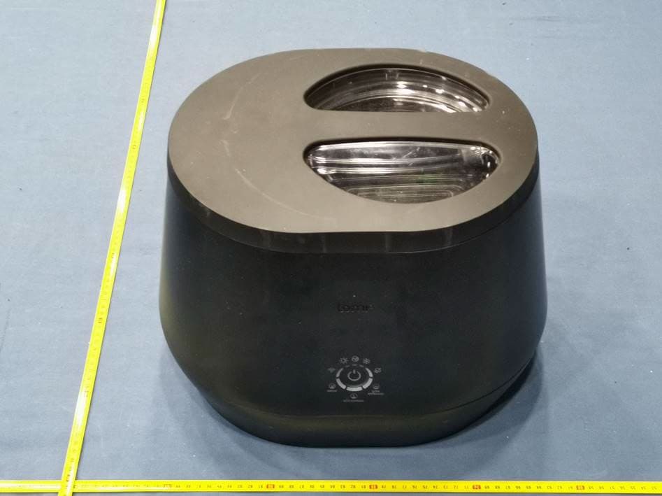
Click to zoom
Application Details
- Equipment Class
- DSS - Part 15 Spread Spectrum Transmitter
- Date of Grant
- Sep 04, 2023
- Application Purpose
- Original Equipment
- Date of Application
- Sep 04, 2023
- Equipment Note
- Kitchen Composter/Bloom
- Frequency Range
- 2402.00000000 - 2480.00000000
- Country
- Canada
Documents & Files
Document Text
Text extracted from the exhibit documents filed with the FCC. Open a document above to read the original.
Users Manual
EN Download the Lomi app to complete your setup, register your Lomi, track your impact & earn rewards! Or register your Lomi at lomi.com/get-started Visit lomi.com/get-started for more info.Lomi Bloom Instruction Manual 1.1 - 2 EN Table of contents Important safety instructions 3 Product specifications 4 Meet Lomi Bloom 5 Initial setup 6 Lomi Bloom modes 7 Regular use 8 Tips for performance 9 What can I put in my Lomi 10 How to care for Lomi 11 One button functions 12 Troubleshooting 13 How to feed your garden with Lomi Earth 14 How does Lomi help the environment? 14 Frequently asked questions 15 Visit lomi.com/get-started for more info.Lomi Bloom Instruction Manual 1.1 - 3 EN IMPORTANT SAFETY INSTRUCTIONS PLEASE SAVE THESE INSTRUCTIONS Please read all accompanying instruction material before your first use of Lomi. Operation • Heat warning - Contents inside may be hot. Do not remove the lid while Lomi is running. • Do not touch any hot surfaces. Use the lid and bucket handles once a cycle has finished and Lomi has cooled. • Ensure all electrical components (plug, cords) are kept away from water or other liquids to protect against electrical shocks. • Close supervision is necessary when Lomi is used by or near children. • Never lift Lomi by the lid handle as the base could fall. Hold at the base with both hands. • When Lomi is not in use, always ensure the lid remains closed to prevent items from falling into it. • Do not remove Lomi’s lid while it is running. Always turn off and unplug Lomi before opening the lid. • Always unplug the unit when not in use, before cleaning and when adding/ removing parts (such as filters). • If trying to clear a jam, always ensure Lomi is unplugged and do not use your hands. • Do not operate Lomi if the cord, plug or the external fuse is damaged. Similarly, do not operate if Lomi malfunctions or is dropped or damaged. Please contact our Lomi support team [email protected] for examination or repair. • Do not use any attachments not recommended or sold by Pela as these could damage Lomi or otherwise. • Do not use Lomi for anything other than its intended use. Do not alter or adapt Lomi in any way. • To avoid entrapment hazard, do not touch the grinding blades when it is moving. Do not run a Lomi cycle when the bucket is empty. Do not remove the bucket and touch the motor coupler when it is moving. Placement • Lomi is intended for household use only. Do not use Lomi outdoors. • Ensure that Lomi sits on a flat surface when in operation. To allow proper air flow, make sure to operate Lomi at least 6 inches away from all walls, in a well ventilated space and avoid placing under overhead cabinets. • Do not place Lomi on or near a hot gas or electric burner, or in a heated oven. • Keep the unit out of direct sunlight and away from any appliances which produce heat. • Do not immerse in water. Cord • Do not let the electric cord hang over the side of a counter or table, or touch hot surfaces. • Always attach the cord plug to Lomi before inserting the plug into the wall outlet. To disconnect, unplug Lomi. • A short power-supply cord (or short detachable power-supply cord) is provided to reduce the risks resulting from becoming entangled in or tripping over a longer cord. • Extension cords (or longer detachable power-supply cords) may be used if care is exercised. • If an extension cord (or a long detachable power-supply cord) is used: 1. The marked electrical rating of the detachable power-supply cord or extension cord should be at least as great as the electrical rating of the appliance; 2. The extension cord should be a grounding type 3-wire cord; and 3. The longer cord should be arranged so that it will not drape over the counter top or tabletop where it can be tripped over, snagged, or pulled on unintentionally (especially by children). Visit lomi.com/get-started for more info.Lomi Bloom Instruction Manual 1.1 - 4 EN Product specifications ModesGrow. Eco-Express. Lomi Approved. Input 120V 60Hz Wattage500 W WiFi 802.11b/g/n 2.4GHz BluetoothV4.2 BR/EDR/Bluetooth LE Energy usage per cycle Grow: ~1kWh Eco-Express: ~ 0.6 kWh Lomi Approved: ~ 0.75 kWh Processing Time Grow: 14–17 hours Eco-Express: 3–5 hours Lomi Approved: 5–7 hours PhasesHeating. Mixing. Cooling. Capacity3L Cleaning1.5 hours Waste weight reduction 70–90% Weight (out of box)19 lbs (8.7kg) Dimensions (out of box)16” W x 13” D x 12” H Noise level< 60dB Visit lomi.com/get-started for more info.Lomi Bloom Instruction Manual 1.1 - 5 EN Clear lid A clear viewing window allows you to see the transformation of waste into nutrient-rich Lomi Earth! Align the arrow on the side of the lid with the unlock icon & twist to secure. Keep the lid secured while Lomi is running a cycle, and twist off when the cycle is complete. Remember, do not lift Lomi by the lid handle. WiFi connected This smart appliance connects to the Lomi app using WiFi, so you can see the status of your Lomi cycle and track the positive impact you’re making on the planet. See page 6 for set up instructions. Two refillable filters Top filter This cylindrical filter is designed to insert easily next to the bucket when Lomi’s lid is removed. To refill, remove the filter and twist the top off. Back filter Sits at the back of the unit. Push down the tab to pull off the back filter panel. Lift out the filter and slide the top off it to refill. Removable bucket This bucket has a built in grinder to process your food waste and Lomi Approved compostables. Made from aluminium, the bucket has a ceramic non-stick coating, and is dishwasher safe. Arrows on the bucket rim align with arrows on the interior of the unit. To remove the bucket, simply lift it up with the handle, and align the arrows to slide back in. Meet Visit lomi.com/get-started for more info.Lomi Bloom Instruction Manual 1.1 - 6 EN 1. Find the perfect spot for your Lomi • Unpack your Lomi and place it on a flat, dry, stable surface. • You can tuck your Lomi into any corner of your kitchen when no…
Text truncated - open the document above for the full version.
Attestation Statements
OpenMindDevelopmentsCorporation 604-460DoyleAvenue Unit604 Kelowna,BCV1Y0C2 Attention:ApplicationExaminer Re:CertificationdesignatingaU.S.agentforserviceofprocesspursuanttosection2.911(d)(7)oftheFCCrules Towhomitmayconcern, Thisletteristoconfirmboth[AmericasComplianceConsultingLLCdbaiCertifi](“Agent”)and[OpenMind DevelopmentsCorporation](“Applicant”)acknowledgeconsenttoobligationsofeachpartypursuantto47 CFRpart§2.911(d)(7)oftheFCCrulesinregardtotheagentforserviceofprocess. I[DaanvirDhir]HEREBYCERTIFYTHATIamauthorizedtomaketherepresentationsaboveonbehalfofthe Applicant.Ifurtheracknowledgetherequirementtomaintainanagentextendsfornolessthanoneyearafter theterminationofallmarketingandimportationortheconclusionofandcommission-relatedproceeding involvingtheequipmentandagreetoimmediatelynotifytheFCCandIntertekifthereisanychangeinthe statusidentifiedabove. Applicant CompanyName:OPENMINDDEVELOPMENTSCORPORATION ContactName:DaanvirDhir Address:604-460DOYLEAVEKELOWNA,BCCAV1Y0C2,KELOWNA,Canada TelephoneNo:+1-250-681-3164 Email:[email protected] ApplicantFRN:0034140095 Signature:_________________________________ Date:____________________________________ I[PaulAPreston]HEREBYCERTIFYTHATIamauthorizedtomaketherepresentationsaboveonbehalfofthe Agent.Iconsenttotheobligationtoacceptserviceofprocessonbehalfoftheapplicantinregardtoall certificationapplicationstotheFCCsubmittedbyaboveapplicantandagreetoimmediatelynotifytheFCC andIntertekifthereischangeinthisrepresentation. Agent CompanyName:AmericasComplianceConsultingLLCdbaiCertifi ContactName:PaulAPreston Address:1001SWDiskDrive,ste250Office3,Bend,OREGON,97702,USA TelephoneNo:+1-541-636-9896 Email:[email protected] AgentFRN:0033399411 Signature:_________________________________ Date:____________________________________
Attestation Statements
OpenMindDevelopmentsCorporation 604-460DoyleAvenue Unit604 Kelowna,BCV1Y0C2 Attention:ApplicationExaminer Re:CoveredList,locatedathttps://www.fcc.gov/supplychain/coveredlistand47CFRparts§2.903 and§2.911(d)(5)(ii)oftheFCCrules Applicant:OpenMindDevelopmentsCorp. FCCID:2A7PS-LOMIBLOOM Towhomitmayconcern, OpenMindDevelopmentsCorp.(“Applicant”)certifiesthattheequipmentforwhichauthorizationis soughtisnot“covered”equipmentprohibitedfromreceivinganequipmentauthorizationpursuant to47CFRpart§2.903oftheFCCrulesanddoesnotoriginatedirectlyorindirectlyfromany companynamedonthecoveredlistlocatedinthelinkaboveoranysubsidiaryoraffiliatethereof. Applicantfurthercertifiesthat,asofthedateofthefilingoftheapplication,theApplicantisnot identifiedontheCoveredListasanentityproducing“covered”equipmentandisnotasubsidiaryor affiliateofanysuchentitypursuantto47CFRpart§1.50002andrequiredby47CFRpart §2.911(d)(5)(ii)oftheFCCrules. IHEREBYCERTIFYTHATIamauthorizedtomaketherepresentationsaboveonbehalfofthe ApplicantandagreetoimmediatelynotifyIntertekifthereisanychangeinthestatusidentified above. ______________________________ DaanvirDhir Sr.DirectorofR&D&Sustainability OpenMindDevelopmentsCorp. June16,2023
Cover Letter(s)
OpenMindDevelopmentsCorporation 604-460DoyleAvenue Unit604 Kelowna,BCV1Y0C2 LetterofAgency "I,anofficerofOpenMindDevelopmentsCorporationdoherebyauthorize IntertekTestingServices(Mr.TimLee/HerbertWong/KennethWong)toact onourbehalfinfrontoftheFederalCommunicationsCommissionwithrespect toallmattersrelatingtocertificationofequipmentunderPart15andPart18of theFCCRulesuntilfurthernotice." Ifurthercertifythatnoparty(asdefinedin§1.2002(b)ofCFR47,2004)tothis application,includingmyself,issubjecttoadenialoffederalbenefits,that includesFCCbenefits,pursuanttoSection5301oftheAnti-DrugAbuseActof 1988,21U.S.C.,862. Datedthis__July__day__04__of2023__ By____________________________ Signature DaanvirDhir ____________________________ PrintedName Sr.DirectorofR&D&Sustainability ____________________________ Title Remark:Thepersonwhosignsthisauthorizationlettermustbethegranteecontactofrecordinthe GranteeCodedatabase.
Cover Letter(s)
OpenMindDevelopmentsCorporation 604-460DoyleAvenue Unit604 Kelowna,BCV1Y0C2 July31,2023 Attention:ApplicationExaminer RE:RequestforConfidentiality Applicant:OpenMindDevelopmentsCorporation FCCID:2A7PS-LOMIBLOOM ToWhomItMayConcern: PermanentConfidentiality RequestisherebysubmittedbyOpenMindDevelopmentsCorporationtowithholdpermanently frompublicreviewcertainportionsoftheapplicationforequipmentcertificationforthereferenced FCCidentifiers.Thisrequestforconfidentialityismadepursuantto47CFR0.457(d)and0.459ofthe FCCRules.Inparticular,thefollowingsectionsoftheapplicationaretobekeptpermanently confidential: ● Schematics ● DetailedBlockDiagrams ● DetailedOperational/FunctionalDescription Rationaleforrequestforconfidentiality: OpenMindDevelopmentsCorporationhasinvestedconsiderabletimeandmaterialsinresearch anddevelopmenttoproducethereferencedproduct.Disclosureofthepermanentlyconfidential portionsofthisapplicationtocompetitorswouldnotonlygivethemsignificantcompetitive advantagesindevelopingsimilarproducts,butwouldalsodisclosesuccessfulimplementationof unpublished,leadingedgetechnologydevelopedbyus. Thefeeforconfidentialityhasbeensubmittedalongwiththefeeforcertification.Ifyouhave questionsorneedfurtherinformation,pleasecontacttheundersigned. Sincerely, __________________________________ DaanvirDhir Sr.DirectorofR&D&Sustainability OpenMindDevelopmentsCorporation
External Photos
INTERTEK TESTING SERVICES FCC ID: 2A7PS-LOMIBLOOM IC: 28807-LOMIBLOOM Equipment Photographs (External) INTERTEK TESTING SERVICES FCC ID: 2A7PS-LOMIBLOOM IC: 28807-LOMIBLOOM Equipment Photographs (External) INTERTEK TESTING SERVICES FCC ID: 2A7PS-LOMIBLOOM IC: 28807-LOMIBLOOM Equipment Photographs (External) INTERTEK TESTING SERVICES FCC ID: 2A7PS-LOMIBLOOM IC: 28807-LOMIBLOOM Equipment Photographs (External) INTERTEK TESTING SERVICES FCC ID: 2A7PS-LOMIBLOOM IC: 28807-LOMIBLOOM Equipment Photographs (External) INTERTEK TESTING SERVICES FCC ID: 2A7PS-LOMIBLOOM IC: 28807-LOMIBLOOM Equipment Photographs (External)
ID Label/Location Info
INTERTEK TESTING SERVICES FCC ID: 2A7PS-LOMIBLOOM IC: 28807-LOMIBLOOM Equipment Photographs (External)
Internal Photos
INTERTEK TESTING SERVICES FCC ID: 2A7PS-LOMIBLOOM IC: 28807-LOMIBLOOM Equipment Photographs (Internal) INTERTEK TESTING SERVICES FCC ID: 2A7PS-LOMIBLOOM IC: 28807-LOMIBLOOM Equipment Photographs (Internal) INTERTEK TESTING SERVICES FCC ID: 2A7PS-LOMIBLOOM IC: 28807-LOMIBLOOM Equipment Photographs (Internal) INTERTEK TESTING SERVICES FCC ID: 2A7PS-LOMIBLOOM IC: 28807-LOMIBLOOM Equipment Photographs (Internal) INTERTEK TESTING SERVICES FCC ID: 2A7PS-LOMIBLOOM IC: 28807-LOMIBLOOM Equipment Photographs (Internal) INTERTEK TESTING SERVICES FCC ID: 2A7PS-LOMIBLOOM IC: 28807-LOMIBLOOM Equipment Photographs (Internal) INTERTEK TESTING SERVICES FCC ID: 2A7PS-LOMIBLOOM IC: 28807-LOMIBLOOM Equipment Photographs (Internal) INTERTEK TESTING SERVICES FCC ID: 2A7PS-LOMIBLOOM IC: 28807-LOMIBLOOM Equipment Photographs (Internal) INTERTEK TESTING SERVICES FCC ID: 2A7PS-LOMIBLOOM IC: 28807-LOMIBLOOM Equipment Photographs (Internal) INTERTEK TESTING SERVICES FCC ID: 2A7PS-LOMIBLOOM IC: 28807-LOMIBLOOM Equipment Photographs (Internal) INTERTEK TESTING SERVICES FCC ID: 2A7PS-LOMIBLOOM IC: 28807-LOMIBLOOM Equipment Photographs (Internal) INTERTEK TESTING SERVICES FCC ID: 2A7PS-LOMIBLOOM IC: 28807-LOMIBLOOM Equipment Photographs (Internal)
RF Exposure Info
INTERTEK TESTING SERVICE FCC ID: 2A7PS-LOMIBLOOM IC: 28807-LOMIBLOOM MPE Analysis Report For Maximum Permissible Exposure (MPE) evaluation of the unit, the maximum power density at 20 cm from this transmitter shall be less than the General Population / Uncontrolled MPE limit in OET Bulletin 65 and meet the requirement listed in KDB447498 D01 v06. 1)For the Bluetooth portion of the unit, the measured powers among all the measured channels were within its production tolerance. The antenna gain is 2.3 dBi = 1.70 (num gain) and its maximum source-based time-averaging duty factor is 100%. From these data and its operating configuration, the exposed power density at a distance (R) of 20 cm from the center of radiation of the antenna can be calculated according to OET Bulletin 65 as follow: The EIRP radiated power = 12 dBm + 2.3 dBi = 14.3 dB m ( 26.9 mW) The radiated (EIRP) source-based time-averaging output power = (26.9 * 1) mW = 26.9 mW The power density at 20 cm = 26.9 / 4πR 2 = 0.0054 m W cm -2 2)For the WiFi portion of the unit, the measured powers among all the measured channels were within its production tolerance. The antenna gain is 2.3 dBi = 1.70 (num gain) and its maximum source-based time-averaging duty factor is 100%. From these data and its operating configuration, the exposed power density at a distance (R) of 20 cm from the center of radiation of the antenna can be calculated according to OET Bulletin 65 as follow: The EIRP radiated power = 20.5 dBm + 2.3 dBi = 22.8 dBm (190.5 mW) The radiated (EIRP) source-based time-averaging output power = (190.5 * 1) mW = 190.5 mW The pow er density at 20 cm = 190.5 / 4πR 2 = 0.038 mW cm -2 I n the frequency range of 1,500 - 100,000MHz, the MPE limit is 1.0 mWcm-2 for general population and uncontrolled exposure. As the measured power density at 20cm from the transmitter is lower than the MPE limit, the compliance to the MPE limit can be ensured by indicating the minimum 20cm separation between the transmitter's radiating structures and body of the user or nearby persons. The following RF exposure statement is proposed to be included in the user manual: “ FCC RF Radiation Exposure Statement Caution: To maintain compliance with the FCC’s RF exposure guidelines, place the unit at least 20cm from nearby persons.” INTERTEK TESTING SERVICE FCC ID: 2A7PS-LOMIBLOOM IC: 28807-LOMIBLOOM In addition, for this product with multiple transmitter and antenna (Bluetooth and WiFi), the requirement of Simultaneous Transmission evaluation has also been considered and has complied with the following conditions of the worse-case; MPE1/Limit1 + MPE2/Limit2 ≤ 1 Thus, 0.0054/1 + 0.038/1 = 0.0434 ≤ 1 Bluetooth WiFi It i s concluded that no Simultaneous Transmission evaluation is required.
Test Report
TEST REPORT 2/F., Garment Centre, 576 Castle Peak Road, Kowloon, Hong Kong SAR, China. Telephone: (852) 2173 8888 Facsimile: (852) 2785 5487 www.intertek.com Intertek’s standard Terms and Conditions can be obtained at our website http://www.intertek.com/terms/. The test report only allows to be revised within the retention period unless further standard or the requirement was noticed. This report is for the exclusive use of Intertek's Client and is provided pursuant to the agreement between Intertek and its Client. Intertek's responsibility and liability are limited to the terms and conditions of the agreement. Intertek assumes no liability to any party, other than to the Client in accordance with the agreement, for any loss, expense or damage occasioned by the use of this report. Only the Client is authorized to permit copying or distribution of this report and then only in its entirety. Any use of the Intertek name or one of its marks for the sale or advertisement of the tested material, product or service must first be approved in writing by Intertek. The observations and test results in this report are relevant only to the sample tested. This report by itself does not imply that the material, product, or service is or has ever been under an Intertek certification program. © 2017 Intertek Page 1 of 47 Report Number: 23031222HKG-002 Application for Original of 47 CFR Part 15 Certification New Family of RSS-247 Issue 2 Equipment This report contains the data of Bluetooth 3.0 portion only. FCC ID: 2A7PS-LOMIBLOOM IC: 28807-LOMIBLOOM Prepared and Checked by: Approved by: Signed On File Leung Chun Ning, Peter Assistant Engineer Wong Cheuk Ho, Herbert Assistant Supervisor Date: June 15, 2023 TEST REPORT OPEN MIND DEVELOPMENTS CORPORATION Intertek Report No: 23031222HKG-002 Page 2 of 47 GENERAL INFORMATION Applicant Name: OPEN MIND DEVELOPMENTS CORPORATION Applicant Address: 604-460 DOYLE AVE., UNIT 604, KELOWNA, BC V1Y 0C2, Canada. FCC Specification Standard: FCC Part 15, October 1, 2021 Edition FCC ID: 2A7PS-LOMIBLOOM FCC Model: 80201-LOMI-BLOOM-WH Additional Model: 80202-LOMI-BLOOM-SAGE, 80203-LOMI-BLOOM-BLK, 80204-LOMI-BLOOM-D, 80205-LOMI-BLOOM-E, 80206-LOMI-BLOOM-F, 80207-LOMI-BLOOM-G, 80208-LOMI-BLOOM-H, 80209-LOMI-BLOOM-I IC Specification Standard: RSS-247 Issue 2, February 2017 RSS-Gen Issue 5 Amendment 2, February 2021 IC: 28807-LOMIBLOOM HVIN: 80201 PMN: 80201-LOMI-BLOOM-WH, 80202-LOMI-BLOOM-SAGE, 80203-LOMI-BLOOM-BLK, 80204-LOMI-BLOOM-D, 80205-LOMI-BLOOM-E, 80206-LOMI-BLOOM-F, 80207-LOMI-BLOOM-G, 80208-LOMI-BLOOM-H, 80209-LOMI-BLOOM-I Type of EUT: Spread Spectrum Transmitter Description of EUT: Kitchen Composter/Bloom Sample Receipt Date: March 30, 2023 Date of Test: April 04, 2023 to April 08, 2023 Report Date: June 15, 2023 Environmental Conditions: Temperature: +10 to 40°C Humidity: 10 to 90% TEST REPORT OPEN MIND DEVELOPMENTS CORPORATION Intertek Report No: 23031222HKG-002 Page 3 of 47 Conclusion: Test was conducted by client submitted sample. The submitted sample as received complied with the 47 CFR Part 15 / RSS-247 Issue 2 Certification. TEST REPORT OPEN MIND DEVELOPMENTS CORPORATION Intertek Report No: 23031222HKG-002 Page 4 of 47 TABLE OF CONTENTS 1.0 TEST RESULTS SUMMARY & STATEMENT OF COMPLIANCE ............................................ 5 1.1 Summary of Test Results ................................................................................................. 5 1.2 Statement of Compliance ................................................................................................ 5 2.0 GENERAL DESCRIPTION ................................................................................................ 6 2.1 Product Description......................................................................................................... 6 2.2 Test Methodology ........................................................................................................... 6 2.3 Test Facility ..................................................................................................................... 7 2.4 Related Submittal(s) Grants ............................................................................................ 7 3.0 SYSTEM TEST CONFIGURATION ..................................................................................... 8 3.1 Justification ..................................................................................................................... 8 3.2 EUT Exercising Software .................................................................................................. 9 3.3 Details of EUT and Description of Accessories ............................................................... 10 3.4 Measurement Uncertainty ............................................................................................ 10 4.0 TEST RESULTS ............................................................................................................. 11 4.1 Maximum Conducted Output Power at Antenna Terminals ......................................... 11 4.2 Maximum 20 dB RF Bandwidth ..................................................................................... 14 4.3 Minimum Number of Hopping Frequencies .................................................................. 17 4.4 Minimum Hopping Channel Carrier Frequency Separation ........................................... 19 4.5 Average Channel Occupancy Time ................................................................................ 21 4.6 Out of Band Conducted Emissions ................................................................................ 23 4.7 Field Strength Calculation.............................................................................................. 32 4.8 Transmitter Radiated Emissions in Restricted Bands and Spurious Emissions ............... 33 4.8.1 Radiated Emission Configuration Photograph ............................................................ 34 4.8.2…
Text truncated - open the document above for the full version.
Test Report
Small Size 2.4GHz PCB Antenna-AN043 1 KEYWORDS PCB antenna Average Gain 2dBi; Peak Gain 2.3dBi ESP32 IOT application 2.4 GHz Inverted F Antenna 2 INTRODUCTION The PCB antenna described in this application note is now used on ESP32 module reference design. However, it can also be used in all 2.4 GHz designs, especially small space is required for the antenna. This application note describes the antenna dimensions, the RF performance and considerations for complying with regulatory limits when using this design. The suggested antenna design requires no more than 15.2 x 5.7 mm of space and ensures a VSWR ratio of less than 2 across the 2.4 GHz ISM band when connected to a 50 ohm source. 3 ANTENNA DESIGN The PCB antenna on the ESP32 Module reference design is a meandered Inverted F Antenna (IFA). The Manufacturer: Espressif Systems (Shanghai) Co., Ltd. Address: #204 Block 2 690 Bibo Road, Zhang Jiang High-Tech Park, Shanghai, China Antenna Model Numbner: ESP-ANT B IFAwasdesignedtomatchanimpedanceof50ohmat2.45GHz.Thusnoadditionalmatching componentsarenecessary. 3.1DesignGoals Thereflectionatthefeedpointoftheantennadetermineshowmuchoftheappliedpoweris deliveredtotheantenna.Areflectionoflessthan-10dBacrossthe2.4GHzISMband,when connectedtoa50ohmsource,wasadesigngoal.Reflectionoflessthan-10dB,orVSWRlessthan2, ensuresthatmorethan90%oftheavailablepowerisdeliveredtotheantenna.Bandwidthisinthis documentdefinedasthefrequencybandwheremorethan90%oftheavailablepowerisdeliveredto theantenna.AnotherdesigngoalwastofitthesizeofthePCBantennaontheesp32Moduleandto obtaingoodperformancealsowhenitisusedinIOTapplications. 3.2Simulation IE3DfromZeland,whichisanelectromagneticsimulationtool,wasusedtodesigntheantenna.The accuracyofthesimulationiscontrolledbythemesh.Anincreaseofthemeshincreasesthesimulation time.Thus,forinitialsimulationsmesh=1shouldbeused.Whenafairlygoodresultisachieveda highermeshshouldbeusedtoobtainmoreaccurateresults.Comparisonofsimulationand measurementresultsshowsthatthemeasuredreflectionisbetweentheresultobtainedwithmesh= 5andmesh=1;seeFigure2fordetails. Figure2:ComparisonofSimulationandMeasurementsResults 3.3LayoutandImplementation Smallchangesoftheantennadimensionsmayhavelargeimpactontheperformance.Thereforeitis stronglyrecommendedtomakeanexactcopyofthereferencedesigntoachieveoptimum performance.ItisalsorecommendedtousethesamethicknessandtypeofPCBmaterialasusedin thereferencedesign.Tocompensateforathicker/thinnerPCBtheantennacouldbemadeslightly shorter/longer. Figure3:AntennaDimensions L13.94 L22.70 L35.00 L42.64 L52.00 L64.90 W10.90 W20.50 D10.50 D20.30 D30.30 D40.50 D51.40 D61.70 Table1:AntennaDimensions 4TESTRESULTS Reflection,radiationpatternandvariationofoutputpoweracrossawidefrequencybandwere measuredtoverifytheperformanceofthePCBantenna. 4.1Reflection Allthereflectionmeasurementswereperformedwithanetworkanalyzerconnectedtoasemi-rigid coaxcable,whichwassolderedtothefeedpointoftheantenna.Becauseofthesmallsizeantenna andthesmallgroundplanethiskindofmeasurementsisheavilyaffectedbythepresenceand placementofthecoaxcable.Thisinfluencecanresultinasmalluncertaintyinresonancefrequency andmeasuredreflection.Typicallydifferentplacementofthesemi-rigidcoaxcablecouldchangethe resonancefrequencywith5-10MHzandthereflectionwith3-4dB. Figure4:InfluenceofPlasticEncapsulationandTestPins ThesizeofthegroundplaneaffectstheperformanceofthePCBantenna.Solderingesp32toatest boardincreasesthesizeofthegroundplaneandthustheperformanceisaffected.However, bandwidthstillcanbeenoughtocoverthewhole2.4GHzISMband. 4.2RadiationPattern Theradiationpatternfortheantennaimplementedontheesp32referencedesignhasbeenmeasured inananechoicchamber.Figure6throughFigure11showsradiationpatternsforthreeplanes,XY,XZ andYZ,measuredwithverticalandhorizontalpolarization.Allmeasurementswereperformedwith0 dBmoutputpower.Figure5showshowthedifferentradiationpattersarerelatedtothepositioningof theantenna. Figure5:HowtoRelatetheAntennatotheRadiationPatterns Figure6:AN043XYPlane Figure7:AN043XZPlane Figure7:AN043YZPlane 4.3OutputPower Tomakearealisticbandwidthmeasurementoftheantennaasmalltestprogramwasused.Thetest programsteppedthecenterfrequencyofacarrierfrom2.3to2.8GHz.Thisbandwidthmeasurement wasalsodonetoverifytheresultfromthereflectionmeasurements,describedinsection5.1.The outputpowerwasmeasuredusingmaxholdonaspectrumanalyzer.CC2511wasprogrammedfor0 dBmoutputpowerandtheantennawashorizontallyorientedanddirectedtowardsthereceiving antenna.Thiscorrespondsto0°intheXYplaneonFigure6.Thebandwidthmeasurementswerenot performedwithacorrectionfactoronthespectrumanalyzer.Thus,theresultsinFigure15andFigure 16onlyshowtherelativechangesinoutputpowerandnottheactuallevel.Figure15showsthe bandwidthoftheantennawhenthedongleisnotconnectedtoacomputer.Theresultshowsthatthe antennahasavariationinoutputpoweroflessthan3dBacrossafrequencybandofmorethan350 MHz.Thisdemonstratesthattheantennahasabroadbandcharacteristic.Maximumoutputpoweris measuredtobeat2.54GHz.ThusifthesameantennaisimplementedonaPCBwithsimilarsizeandif theapplicationisonlyintendedforstandaloneusagetheantennacouldbemadeslightlylongerto obtainbestperformanceat2.42GHz. Figure8:OUTPUTPOWER,esp32 5.4SpuriousEmissionandHarmonics Table2showsmeasuredoutputpowerandemissionatthesecondharmonic.Abovethesecond harmonicnopeaksweredetectedwhenmeasuringTXemission.ThiscanbeseenfromFigure16. ThesemeasurementswereperformedaccordingtoFCCrequirements. Table2:MeasuredLevelofOutputPowerandHarmonics FCClimitforoutputpowerandTXspuriousemissionareshowninTable3.FCCallowsforupto20dB higheremissionifdutycyclingisused.Thus,itispossibletousetheantennadescribedinthis documentandbecompliantwithFCCregulation. FCC15.247FCC15.249 2.4–2.483GHz125dBμV/m 116dBμV/m** 94dBμV/m 2.harm54dBμV/m54dBμV/m *Dependsonthepowerclass. **Dependsonthenumberofchannelsbeingused. Table3:FCCLimits 5CONCLUSION Thisapplicationnoteshowsthatitispossibletoimplementa2.4GHzantennaonasmallareaandstill achievegoodperformance.Table4liststhemostimportantpropertiesoft…
Text truncated - open the document above for the full version.
Test Setup Photos
INTERTEK TESTING SERVICE FCC ID: 2A7PS-LOMIBLOOM IC: 28807-LOMIBLOOM Configuration Photographs Radiated Emissions (30MHz – 1GHz) (Front View) INTERTEK TESTING SERVICE FCC ID: 2A7PS-LOMIBLOOM IC: 28807-LOMIBLOOM Configuration Photographs Radiated Emissions (30MHz - 1GHz) (Back View) INTERTEK TESTING SERVICE FCC ID: 2A7PS-LOMIBLOOM IC: 28807-LOMIBLOOM Configuration Photographs Radiated Emissions (Above 1GHz) (Front View) INTERTEK TESTING SERVICE FCC ID: 2A7PS-LOMIBLOOM IC: 28807-LOMIBLOOM Configuration Photographs Radiated Emissions (Above 1GHz) (Back View) INTERTEK TESTING SERVICE FCC ID: 2A7PS-LOMIBLOOM IC: 28807-LOMIBLOOM Configuration Photographs Worst-Case Conducted Emissions (Front View) INTERTEK TESTING SERVICE FCC ID: 2A7PS-LOMIBLOOM IC: 28807-LOMIBLOOM Configuration Photographs Worst-Case Conducted Emissions (Side View)
Contact Information
Applicant
Daanvir Dhir(Sr. Director of R&D & Sustainability)
Technical Contact
Intertek Testing Services Hong Kong Ltd.Kenneth Wong
[email protected]+85239126902
2/F., Garment Centre, · Hong Kong
Non-Technical Contact
Intertek Testing Services Hong Kong Ltd.Kenneth Wong
[email protected]+85239126902
Test Firm
Intertek Testing Services Hong Kong Ltd.Billy Chow
Technical Specifications
| # | Rule Parts | Frequency Range | Power Output |
|---|---|---|---|
| 1 | 15C | 2.40 GHz - 2.48 GHz | 15.70 mW |
Other Applications from OPEN MIND DEVELOPMENTS CORPORATION
2A7PS-JUICEBOX
Jul 03, 2026JuiceBox Power Bank
Equipment Class
DCD - Part 15 Low Power Transmitter Below 1705 kHz