2A84DMAXVIBPLUSVIBRATION MASTER PLUS
INNOVATION STREET PTE.LTD.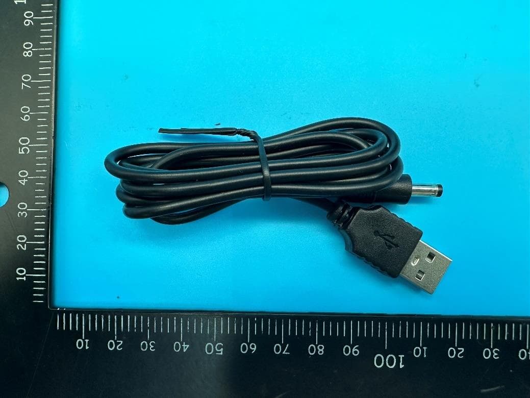
Click to zoom
Application Details
- Equipment Class
- DSC - Part 15 Security/Remote Control Transmitter
- Date of Grant
- Mar 22, 2023
- Application Purpose
- Original Equipment
- Date of Application
- Mar 22, 2023
- Equipment Note
- VIBRATION MASTER PLUS
- Frequency Range
- 433.92500000 - 433.92500000
- Company
- INNOVATION STREET PTE.LTD.
- Country
- Singapore
Documents & Files
Document Text
Text extracted from the exhibit documents filed with the FCC. Open a document above to read the original.
Users Manual
YOUR VIBRATION MASTER+ Congratulations on your purchase of Vibration Master+, the world’s most elite pleasure stroker equipped with four independent motors delivering 360degree earth-shattering sensations. Please take a moment to read through this user manual before using the stroker. Make sure to charge your VIBRATON MASTER+ together with the remote before the first use. In case the battery is getting low, the LED around button area starts flashing fast. Insert the DC plug into the DC port. LED will start flashing slowly indicating charging. Once fully charged LED stops flashing. Charge at least once every 6 months to protect and extend battery lifetime. IMPORTANT: Use only original USB charging cable provided with your MAXTASY product. USB adapter must not have higher charging current than 1A (one amper). CHARGING Charing time Vibration Master+: 180min Running time Vibration Master+: 120min Charing time Remote: 60min Running time Remote: 12hrs REMOTE CONTROL On/Off Button • Mode Button • • Charging Port • Plus Button • Minus Button BUTTONS’ CONTROL WITHOUT THE REMOTE BUTTONS’ CONTROL WITH THE REMOTE Press and hold On/Off Button on the main unit until it lights up = product is stand-by mode Press and hold On/Off Button on the remote until it lights up = remote control is activated Press On/Off Button or Plus Button on the remote = vibration mode 1 turns on Press Mode Button on the remote = move between vibration modes (total of 10 vibration modes) Press Plus Button on the remote shortly once = vibration intensity increases (total of 10 vibration intensity levels) Press Minus Button on the remote shortly once = vibration intensity decreases Press On/Off Button on the remote shortly = vibration stops Press and hold On/Off Button on the remote = remote control is de-activated and light turns off TIP: The remote-control range is 5meters On/Off Button • Mode Button • • Plus Button • Minus Button Clean the outer case with a damp cloth or tissue and dry after use. IMPORTANT: Never let water come inside the main housing case. TIP: For more details visit www.maxtasy.com/howtouse Make sure the main unit as well as the remote are in stand-by mode, both On/Off buttons are light up Read BUTTON’S CONTROL WITH THE REMOTE Remote does not work Material: Dimensions: Weight: Battery: Noise Level: Charging Time Vibration Master+: Running Time Vibration Master+: Charging Time Remote: Running Time Remote: Remote Range: Remote Frequency: Housing and buttons ABS, inner sleeve TPE Height 10” (255mm) Outer Diameter 3” (85mm) Insertable depth 5¼“ (135mm standard version) Insertable depth 5¾“ (147mm realistic version) 650 g (Standard version) 670 g (Realistic version) Li-Ion 2600 mAh 3.7V < 45dB 180min 120min 60min 12hr 5meters 433MHz Designed and developed in California U.S.A. Manufactured for Maxtasy in China FCC ID 2A84DMAXVIBPLUS Patented DE file number 20 2021 105 755.6 WEBSITE: www.maxtasy.com SUPPORT: [email protected] FCC Warning This device complies with part 15 of the FCC Rules. Operation is subject to the following two conditions: (1) This device may not cause harmful interference, and (2) this device must accept any interference received, including interference that may cause undesired operation. Any Changes or modifications not expressly approved by the party responsible for compliance could void the user's authority to operate the equipment. Note: This equipment has been tested and found to comply with the limits for a Class B digital device, pursuant to part 15 of the FCC Rules. These limits are designed to provide reasonable protection against harmful interference in a residential installation. This equipment generates uses and can radiate radio frequency energy and, if not installed and used in accordance with the instructions, may cause harmful interference to radio communications. However, there is no guarantee that interference will not occur in a particular installation. If this equipment does cause harmful interference to radio or television reception, which can be determined by turning the equipment off and on, the user is encouraged to try to correct the interference by one or more of the following measures: -Reorient or relocate the receiving antenna. -Increase the separation between the equipment and receiver. -Connect the equipment into an outlet on a circuit different from that to which the receiver is connected. -Consult the dealer or an experienced radio/TV technician for help. The device has been evaluated to meet general RF exposure requirement. The device can be used in portable exposure condition without restriction.
Attestation Statements
Atta�tatlon St�t(gm@nts 27 th Feb. 2023 TO: Federal Communications Cemmisslon Authorlzatlen and Evaluation Division 74S5 OG!kland Mills Road Colljmbla, MD 21046, USA RE: A ttestation Statements Part 2J)11(d)(i) request for 2A84D I nnovation Street PTE. LTD, the undersigned, hereby authorl%e Michelle Liss LLC to act as oyr designated LJ .S, agent for service of process, Innovation Street PTE. LTD accepts to maintain an agen-t for no less than one year after the grantee has terminated all marketing and Importation or the conclusion of any Commls:ilon-related proceeding Involving the equipment. Michelle Liss LLC accepts the responsibility t o act as designated U.S. agent for service of process, provides an agent for no less than one year after the grantee has terminated all marketing and Importation or the conclusion of any Commission-related proceeding involving the equipment. Applicant Information: Company name: Innovation Street PTE. LTD Contact Name: Mark T. Address: 141 Cecil Street #08-07, Singapore 069541 Tel ephone No: Email: [email protected] u.s, Agent Information: Company Name: Michelle Liss LLC Address: 850 Bluebell Ct Carlsbad, CA 92011 FRN: 0033507237 Contact Name: Marty Gozdzik Telephone No: Email: ma [email protected] Applicant Signature: Applicant printed na Agent Signature: {if the agent Is different from the applicant) A gent printed name: Marty Gozdzik
External Photos
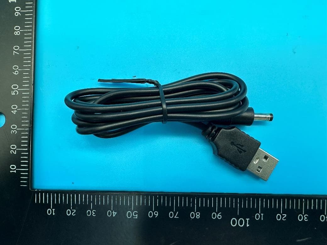
Page 1 of 4 Report No.: LGT22J052 Appendix - External Photographs of EUT Constructional Details FCC ID: 2A84DMAXVIBPLUS Model Name: MAXVIBPLUS Photo 1 Photo 2 Receiver Transmitter Page 2 of 4 Report No.: LGT22J052 Photo 3 Photo 4 Page 3 of 4 Report No.: LGT22J052 Photo 5 Photo 6 Page 4 of 4 Report No.: LGT22J052 Photo 7 Photo 8
ID Label/Location Info
Label Maxtasy Vibration Model name: MAXVIBPLUS FCC ID:2A84DMAXVIBPLUS INNOVATION STREET PTE.LTD. 141 CECIL STREET #08-07 TUNG ANN ASSOCIATION BUILDING SINGAPORE 069541 Importer:XXXXXXXXX Address:XXXXXXXXXX
Internal Photos
Page 1 of 2 Report No.: LGTXXXXXX Appendix - Internal Photographs of EUT Constructional Details FCC ID: 2A84DMAXVIBPLUS Model Name: MAXVIBPLUS Photo 1 Photo 2 ANT Page 2 of 2 Report No.: LGTXXXXXX Photo 3 Photo 4
RF Exposure Info
FCC ID:2A84DMAXVIBPLUS RF EXPOSURE EVALUATION METHOD SAR Test Exclusion Thresholds for 100 MHz – 6 GHz and ≤ 50 mm Approximate SAR Test Exclusion Power Thresholds at Selected Frequencies and Test Separation Distances are illustrated in the following Table. The 1-g and 10-g SAR test exclusion thresholds for 100 MHz to 6 GHz at test separation distances ≤ 50 mm are determined by: [(max. power of channel, including tune-up tolerance, mW)/(min. test separation distance, mm)] · [√f(GHz)] ≤ 3.0 for 1-g SAR and ≤ 7.5 for 10-g extremity SAR,where f(GHz) is the RF channel transmit frequency in GHz Power and distance are rounded to the nearest mW and mm before calculation The result is rounded to one decimal place for comparison The test exclusions are applicable only when the minimum test separation distance is ≤ 50 mm and for transmission frequencies between 100 MHz and 6 GHz. When the minimum test separation distance is < 5 mm, a distance of 5 mm is applied to determine SAR test exclusion. FCC ID:2A84DMAXVIBPLUS The Worst Case Mode 433.925MHz Detector PEAK field strength 58.96dBuV/m(-36.24dBm) Remark: The worst case gain of the antenna is -20dBi. -20dBi logarithmic terms convert to numeric result is nearly 0.1 0.4339 -36.24 -36 0.000251189 0.00003 3 Limit Maximum Peak Conducted Output Power (dBm) frequency (GHz) Tune up Power (dBm) Tune up Power (mW) Result Threshold at which no SAR required is 0.00003≤ 3.0 for 1-g SAR, Separation distance is 5mm.
Test Report
Antenna Type: PCB Antenna Antenna Gain: -20dBi All measurements were performed radiated and therefore additional antenna gain documentation is not required 1mm 8.2mm 27mm 17mm
Test Report
The test report is effective only with both signature and specialized stamp. This report shall not be reproduced except in full without the written approval of the Laboratory. The results in this report only apply to the tested sample. Shenzhen LGT Test Service Co., Ltd. Tel: 0755-89668180 E-mail:[email protected] Web: www.lgt-cert.com Room 205, Building 13, Zone B, Chen Hsong Industrial Park, No.177 Renmin West Road, Jinsha Community, Kengzi Street, Pingshan New District, Shenzhen, China RF TEST REPORT Product Name: VIBRATION MASTER PLUS Model Name: MAXVIBPLUS FCC ID: 2A84DMAXVIBPLUS Issued For : INNOVATION STREET PTE.LTD. 141 CECIL STREET #08-07 TUNG ANN ASSOCIATION BUILDING SINGAPORE 069541 Issued By : Shenzhen LGT Test Service Co., Ltd. Room 205, Building 13, Zone B, Chen Hsong Industrial Park, No.177 Renmin West Road, Jinsha Community, Kengzi Street, Pingshan New District, Shenzhen, China Report Number: LGT22J052RF02 Sample Received Date: Nov. 23, 2022 Date of Tested: Nov. 23, 2022 – Dec. 26, 2022 Date of Issue: Dec. 26, 2022 Report No.: LGT22J052RF02 Page 2 of 33 TEST REPORT CERTIFICATION Applicant INNOVATION STREET PTE.LTD. Address 141 CECIL STREET #08-07 TUNG ANN ASSOCIATION BUILDING SINGAPORE 069541 Manufacturer INNOVATION STREET PTE.LTD. Address 141 CECIL STREET #08-07 TUNG ANN ASSOCIATION BUILDING SINGAPORE 069541 Product Name VIBRATION MASTER PLUS Trademark N/A Model Name MAXVIBPLUS Sample Status: Normal APPLICABLE STANDARDS STANDARD TEST RESULTS FCC Part 15.231, Subpart C ANSI C63.10-2013 PASS Prepared by: Approved by: Zane Shan Vita Li Engineer Technical Director Report No.: LGT22J052RF02 Page 3 of 33 TABLE OF CONTENTS Page 1. SUMMARY OF TEST RESULTS 6 1.1 TEST FACTORY 7 1.2 MEASUREMENT UNCERTAINTY 7 2. GENERAL INFORMATION 8 2.1 GENERAL DESCRIPTION OF THE EUT 8 2.2 DESCRIPTION OF THE TEST MODES 9 2.3 DESCRIPTION OF NECESSARY ACCESSORIES AND SUPPORT UNITS 9 2.4 EQUIPMENTS LIST 10 3. EMC EMISSION TEST 11 3.1 CONDUCTED EMISSION MEASUREMENT 11 3.2 TEST PROCEDURE 12 3.3 TEST SETUP 12 3.4 TEST RESULTS 13 4. RADIATED EMISSION MEASUREMENT 15 4.1 RADIATED EMISSION LIMITS 15 4.2 TEST PROCEDURE 17 4.3 DEVIATION FROM TEST STANDARD 17 4.4 TEST SETUP 18 4.5 EUT OPERATING CONDITIONS 19 4.6 TEST RESULTS 19 4.7 FIELD STRENGTH CALCULATION 20 5. BANDWIDTH TEST 25 5.1 LIMIT 25 5.2 TEST REQUIREMENTS 25 5.3 TEST PROCEDURE 25 5.4 TEST SETUP 25 5.5 EUT OPERATION CONDITIONS 25 5.6 TEST RESULTS 25 6. DUTY CYCLE 27 6.1 TEST PROCEDURE 27 6.2 TEST SETUP 27 6.3 EUT OPERATION CONDITIONS 27 6.4 TEST RESULTS 28 Report No.: LGT22J052RF02 Page 4 of 33 TABLE OF CONTENTS Page 7. AUTOMATICALLY DEACTIVATE 30 7.1 STANDARD REQUIREMENT 30 7.2 TEST PROCEDURE 30 8. ANTENNA REQUIREMENT 32 8.1 STANDARD REQUIREMENT 32 8.2 EUT ANTENNA 32 APPENDIX I - PHOTOS OF TEST SETUP 33 Report No.: LGT22J052RF02 Page 5 of 33 Revision History Rev. Issue Date Contents 00 Dec. 26, 2022 Initial Issue Report No.: LGT22J052RF02 Page 6 of 33 1. SUMMARY OF TEST RESULTS Test procedures according to the technical standards: FCC Part 15.231,Subpart C Standard Section Test Item Judgment Remark 15.207 Conducted Emission PASS -- 15.205(a)/15.209/ 15.231.(b) Radiated Spurious Emission PASS -- 15.231(a)(1)/ 15.231(b)(2) Transmission requirement PASS -- 15.231(C) 20 dB Bandwidth PASS -- 15.203 Antenna Requirement PASS -- NOTE: (1) ‘N/A’ denotes test is not applicable in this Test Report. (2) All tests are according to ANSI C63.10-2013. Report No.: LGT22J052RF02 Page 7 of 33 1.1 TEST FACTORY Company Name: Shenzhen LGT Test Service Co., Ltd. Address: Room 205, Building 13, Zone B, Chen Hsong Industrial Park, No.177 Renmin West Road, Jinsha Community, Kengzi Street, Pingshan New District, Shenzhen, China Accreditation Certificate A2LA Certificate No.: 6727.01 FCC Registration No.: 746540 CAB ID: CN0136 1.2 MEASUREMENT UNCERTAINTY The reported uncertainty of measurement y ± U, where expended uncertainty U is based on a standard uncertainty multiplied by a coverage factor of k=2, providing a level of confidence of approximately 95 %. Parameter Uncertainty RF Output Power, Conducted ±0.71dB Unwanted Emission, Conducted ±0.63dB Conducted emission ±2.80dB All Emissions, Radiated (0.009-30MHz) ±2.16dB All Emissions, Radiated (30MHz-1GHz) ±4.40dB All Emissions, Radiated (1GHz-18GHz) ±5.49dB Report No.: LGT22J052RF02 Page 8 of 33 2. GENERAL INFORMATION 2.1 GENERAL DESCRIPTION OF THE EUT Product Name VIBRATION MASTER PLUS Trademark N/A Model Name MAXVIBPLUS Series Model N/A Model Difference N/A Frequency band 433.925MHz Power Rating N/A Modulation Type ASK Hardware version number V1.0 Software version number V1.1 Connecting I/O Port(s) N/A Note: 1. For a more detailed features description, please refer to the manufacturer’s specifications orthe User Manual. 2. Table for filed Antenna Ant. Brand Model Name Antenna Type Connector Gain (dBi) NOTE 1 N/A N/A PCB Antenna N/A -20 Antenna Note: The antenna information refer the manufacturer provide report, applicable only to the tested sample identified in the report. Report No.: LGT22J052RF02 Page 9 of 33 2.2 DESCRIPTION OF THE TEST MODES To investigate the maximum EMI emission characteristics generates from EUT, the test system was pre-scanning tested base on the consideration of following EUT operation mode or test configuration mode which possible have effect on EMI emission level. Each of these EUT operation mode(s) or test configuration mode(s) mentioned above was evaluated respectively. Pretest Mode Description Mode 1 TX Mode Mode 1 Charging + TX Mode For Conducted Emission Final Test Mode Description Mode 2 Charging + TX Mode For Radiated Emission Final Test Mode Description Mode 1 TX Mode 2.3 DESCRIPTION OF NECESSARY ACCESSORIES AND SUPPORT UNITS The EUT has been tested as an independent unit together with other necessary accessories or support units. The following support units or accessories were used to form a representative test configuration during the tests. Accessories Equipment Description Manufacturer M…
Text truncated - open the document above for the full version.
Test Setup Photos
Page 1 of 2 Report No.: LGT22J052 Appendix - Test Setup photos FCC ID: 2A84DMAXVIBPLUS Model: MAXVIBPLUS Radiated Spurious Emission Test Setup Photo - Below 1GHz Radiated Spurious Emission Test Setup Photo - Above 1GHz Page 2 of 2 Report No.: LGT22J052 Conducted Emission Test Setup Photo
Contact Information
Applicant
Mark T
Technical Contact
Shenzhen LGT Test Service Co., Ltd.Vita Li
[email protected]+86-0755 89668180
Room 205, Building 13, Zone B, Chen Hsong Industri · Shenzhen · China
Test Firm
Shenzhen LGT Test Service Co., Ltd.Wen Wen
[email protected]0755-89668180
Technical Specifications
| # | Rule Parts | Frequency Range | Power Output |
|---|---|---|---|
| 1 | 15.231 | 433.925 MHz - 433.925 MHz | - |
Other Applications from INNOVATION STREET PTE.LTD.
2A84DMAXSTRPLUS
Mar 22, 2023STROKE MASTER PLUS
Equipment Class
DSC - Part 15 Security/Remote Control Transmitter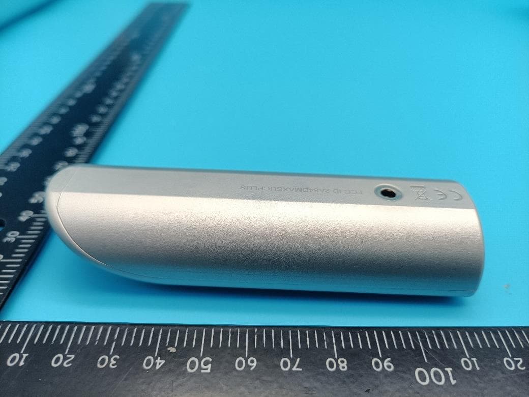
2A84DMAXSUCPLUS
Mar 22, 2023SUCTION MASTER PLUS
Equipment Class
DSC - Part 15 Security/Remote Control Transmitter