2A8C3-240501wireless module
Chengdu Ebyte Electronic Technology Co.,Ltd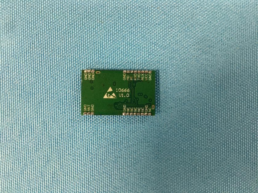
Click to zoom
Application Details
- Equipment Class
- DTS - Digital Transmission System
- Date of Grant
- Aug 21, 2024
- Application Purpose
- Original Equipment
- Date of Application
- Aug 21, 2024
- Equipment Note
- wireless module
- Frequency Range
- 920.30000000 - 924.80000000
- Country
- China
Documents & Files
Document Text
Text extracted from the exhibit documents filed with the FCC. Open a document above to read the original.
Users Manual
User Manual AT command LoRa wireless module CONTENTS 1. OVERVIEW .............................................................................................................. 4 1.1 INTRODUCTION ............................................................................................................................................. 4 1.2 FEATURES .................................................................................................................................................... 4 1.3 APPLICATION ................................................................................................................................................ 6 1.4 FUNCTION INTRODUCTION ............................................................................................................................. 6 2. SPECIFICATION AND PARAMETER ....................................................................... 8 2.1 LIMIT PARAMETER ......................................................................................................................................... 8 2.2 OPERATING PARAMETER ............................................................................................................................... 9 3 SIZE AND PIN DEFINITION ......................................................................................... 11 4. CONNECT TO MCU ................................................................................................... 13 5 FUNCTION DESCRIPTION .......................................................................................... 13 5.1 BROADCASTING ADDRESS ........................................................................................................................... 13 5.2 MONITOR ADDRESS .................................................................................................................................... 14 5.3 RESET ....................................................................................................................................................... 14 5.4 AUX DESCRIPTION ..................................................................................................................................... 14 5.4.1 Indication of UART output ................................................................................................................. 15 5.4.2 Indication of wireless transmitting ..................................................................................................... 15 5.4.3 Configuration procedure of module ................................................................................................... 16 5.4.4 Notes for AUX ................................................................................................................................... 16 Chengdu Ebyte Electronic Technology Co., Ltd E22-900T22S User manual 6 OPERATING MODE .................................................................................................... 17 6.1 MODE SWITCHING .................................................................................................. 17 6.2 NORMAL MODE(MODE 0) ........................................................................................................................ 18 6.3 WOR MODE(MODE 1) ............................................................................................................................ 18 6.4 CONFIGURATION MODE(MODE 2) ............................................................................................................ 18 6.5 DEEP SLEEP MODE(MODE 3) .................................................................................................................. 19 7 REGISTER READ AND WRITE CONTROL .................................................................. 19 7.1 COMMAND FORMAT ..................................................................................................................................... 19 7.2 REGISTER DESCRIPTION .............................................................................................................................. 21 8 REPEATER NETWORKING MODE ............................................................................. 24 9 CONFIGURATION INSTRUCTIONS ON COMPUTER ................................................. 25 10 HARDWARE DESIGN ................................................................................................ 26 11 FAQ ........................................................................................................................... 28 11.1 COMMUNICATION RANGE IS TOO SHORT ..................................................................................................... 28 11.2 MODULE IS EASY TO DAMAGE .................................................................................................................... 28 11.3 BER(BIT ERROR RATE) IS HIGH .............................................................................................................. 29 12 PRODUCTION GUIDANCE ........................................................................................ 29 12.1 REFLOW SOLDERING TEMPERATURE .......................................................................................................... 29 12.2 REFLOW SOLDERING CURVE ...................................................................................................................... 30 15 PACKAGE FOR BATCH ORDER ............................................................................... 31 Chengdu Ebyte Electronic Technology Co., Ltd E22-900T22S User manual REVISION HISTORY ...................................................................................................... 31 ABOUT US ..................................................................................................................... 32 Chengdu Ebyte Electronic Technology Co., Ltd E22-900T22S User manual Copyright ©2012–2018,Chengdu Ebyte Electronic Technology Co.,Lt…
Text truncated - open the document above for the full version.
Attestation Statements
ATTESTATION STATEMENT Applicant: Chengdu Ebyte Electronic Technology Co.,Ltd Add: Building B2, Mould Industrial Park, 199# Xi-Qu Ave, West High-tech Zone, Chengdu, 611731, Sichuan, China Tel: +86-18615799380 Email: [email protected] Date: 2024-07-18 FEDERAL COMMUNICATIONS COMMISSION Authorization and Evaluation Division 7435 Oakland Mills Road Columbia, MD 21046 Ref: Attestation Statements Part 2.911(d)(5)(i), (ii) Filing FCC ID: 2A8C3-240501 Chengdu Ebyte Electronic Technology Co.,Ltd, (“the applicant”) certifies that the equipment for which authorization is sought is not “covered” equipment prohibited from receiving an equipment authorization pursuant to section 2.903 of the FCC rules. Chengdu Ebyte Electronic Technology Co.,Ltd, (“the applicant”) certifies that, as of the date of the filing of the application, the applicant is not identified on the Covered List as an entity producing “covered” equipment. Sincerely, Signed by (printed name): YongLi Signature:
Cover Letter(s)
Applicant: Chengdu Ebyte Electronic Technology Co.,Ltd Add: Building B2, Mould Industrial Park, 199# Xi-Qu Ave, West High-tech Zone, Chengdu, 611731, Sichuan, China Tel: +86-18615799380 Email: [email protected] QA-FR-170-B FCC Authorization Current Date: 2024-07-18 FEDERAL COMMUNICATIONS COMMISSIONS Authorization and Evaluation Division 7435 Oakland Mills Road Columbia, MD 21046 Subject: Agent Authorization To whom it may concern: We Chengdu Ebyte Electronic Technology Co.,Ltd the undersigned, Hereby authorizes Bay Area Compliance Laboratories Corp (Chengdu) to act on its behalf in all matters relating to application for Equipment authorization, including the signing of all documents relating to these matters. All acts carried out by Bay Area Compliance Laboratories Corp (Chengdu) on our behalf shall have the same effect as our own action. We, the undersigned, hereby certify that we are not subject to a denial of federal benefits, that includes FCC benefits, pursuant to Section 5301 of the Anti-Drug Abuse Act of 1988, 21 U.S.C. 862. This authorization is valid until further written notice from the applicant. Sincerely Yours, Client’s Signature: Client’s Name/Title: YongLi/ General manager
Cover Letter(s)
Applicant: Chengdu Ebyte Electronic Technology Co.,Ltd Add: Building B2, Mould Industrial Park, 199# Xi-Qu Ave, West High-tech Zone, Chengdu, 611731, Sichuan, China Tel: +86-18615799380 Email: [email protected] QA-FR-171-A FCC Confidential Authorization Current Date: 2024-07-18 FEDERAL COMMUNICATIONS COMMISSIONS Authorization and Evaluation Division 7435 Oakland Mills Road Columbia, MD 21046 Confidentiality Request regarding application for certification of FCC ID: 2A8C3-240501 Pursuant to Sections 0.457 and 0.459 of the Commission’s Rules, we hereby request confidential treatment of information accompanying this application as outlined below: Circuit Description --- (Long term) Schematic --- (Long term) Block Diagram --- (Long term) The above materials contain proprietary and confidential information not customarily released to the public. The public disclosure of these materials provides unjustified benefits to its competitors in the market. Sincerely, Client’s Signature: Client’s Name/Title: YongLi/ General manager
Cover Letter(s)
Applicant: Chengdu Ebyte Electronic Technology Co.,Ltd Add: Building B2, Mould Industrial Park, 199# Xi-Qu Ave, West High-tech Zone, Chengdu, 611731, Sichuan, China Tel: +86-18615799380 Email: [email protected] Version: 20160531 Difference Description FEDERAL COMMUNICATIONS COMMISSIONS Authorization and Evaluation Division 7435 Oakland Mills Road Columbia, MD 21046 FCC ID: 2A8C3-240501 Current Date: 2024-07-18 We , Chengdu Ebyte Electronic Technology Co.,Ltd, Inc hereby declare that product name: wireless module, multi-listing model number: E220-900T22S、E32-900T20S is (are) electrically identical to test model number: E22-900T22S (such as layout of PCB, schematics, board layout, and internal structures etc.). We declare that the products above are electrically identical, only the configuration of E22-900T22S mode is different in the subpackage length is 240byte, the software communication is encrypted, the configuration of E220-900T22S mode is different in no encryption, no relay subpackage length 200bytes, E32-900T20S subpackage length is 52byte, it cannot be modified.The preceding parameters do not affect the RF parameters. Different models are used in different scenarios. We guarantee all information above-mentioned is true, and notice that we’ll bear all the consequences caused by any false information or concealing Note: The definition of identical should be “electrically identical”. A device will be considered to be electrically identical if no changes are made to the device’s schematics, board layout, component layout, chip sets, resistors and all other electrical aspects of the device. Sincerely, Client’s Signature: Client’s Name/Title: YongLi/ General manager Phone: +86-18615799380 Email: [email protected]
Cover Letter(s)
Applicant/Grantee Chengdu Ebyte Electronic Technology Co.,Ltd FCC ID: 2A8C3-240501 Section 15.212 Modular Transmitters Request for Modular Approval ■ Request for Limited Modular Approval □ Requirements EUT Conditions Comply (Y/N) Single Modular Approval Requirements 1 The radio elements of the modular transmitter must have their own shielding. The physical crystal and tuning capacitors may be located external to the shielded radio elements. Refer to EUT photos. This module have shielding cover. Y 2 The modular transmitter must have buffered modulation/data inputs (if such inputs are provided) to ensure that the module will comply with Part 15 requirements under conditions of excessive data rates or over-modulation. All inputs to the modules are buffered through logic or microprocessor inputs. Refer to Schematics(U3). Y 3 The modular transmitter must have its own power supply regulation. Working voltage 2.7 to 5.5V is regulated by U1(ME6214). Refer to schematics. Y 4 The modular transmitter must comply with the antenna and transmission system requirements of Sections 15.203, 15.204(b) and 15.204(c). The antenna must either be permanently attached or employ a “unique” antenna coupler (at all connections between the module and the antenna, including the cable). The “professional installation” provision of Section 15.203 is not applicable to modules but can apply to limited modular approvals under paragraph (b) of this section. The module has one external monopole antenna with RP-SMA connector and maximum antenna gain 3.5dBi. Y 5 The modular transmitter must be tested in a stand-alone configuration, i.e., the module must not be inside another device during testing for compliance with Part 15 requirements. Unless the transmitter module will be battery powered, it must comply with the AC line conducted requirements found in Section 15.207. AC or DC power lines and data input/output lines connected to the module must not contain ferrites, unless they will be marketed with the module (see Section 15.27(a)). The length of these lines shall be the length typical of actual use or, if that length is unknown, at least 10 centimeters to insure that there is no coupling between the case of the module and supporting The module is tested in astand-alone configuration. Refer to test setup photos. Y equipment. Any accessories, peripherals, or support equipment connected to the module during testing shall be unmodified and commercially available (see Section 15.31(i)). 6 The modular transmitter must be equipped with either a permanently affixed label or must be capable of electronically displaying its FCC identification number. (A) If using a permanently affixed label, the modular transmitter must be labeled with its own FCC identification number, and, if the FCC identification number is not visible when the module is installed inside another device, then the outside of the device into which the module is installed must also display a label referring to the enclosed module. This exterior label can use wording such as the following: “Contains Transmitter ModuleFCC ID: 2A8C3-240501 ” or “Contains FCC ID:2A8C3-240501 .” Any similar wordingthat expresses the same meaning may be used. The Grantee may either provide such a label, an example of which must be included in the application for equipment authorization, or, must provide adequate instructions along with the module which explain this requirement. In the latter case, a copy of these instructions must be included in the application for equipment authorization. (B) If the modular transmitter uses an electronic display of the FCC identification number, the information must be readily accessible and visible on the modular transmitter or on the device in which it is installed. If the module is installed inside another device, then the outside of the device into which the module is installed must display a label referring to the enclosed module. This exterior label can use wording such as the following: “Contains FCC certified transmitter module(s).” Any similar wording that expresses the same meaning may be used. The user manual must include instructions on how to access the electronic display. A copy of these instructions must be included in the application for equipment authorization. Refer to the label. Y 7 The modular transmitter must comply with any specific rules or operating requirements that ordinarily apply to a complete transmitter and the manufacturer must provide adequate instructions along with the module to explain any such requirements. A copy of these instructions must be included in the application for equipment authorization. Refer to user manual Y Signature Printed Name/Title: YongLi/ General manager Phone: +86-18615799380 Email: [email protected] 8 The Modular transmitter must comply with any applicable RF exposure requirements in its final configuration. Refer to MPE calculation in the test report Y A limited modular approval may be granted for single or split modular transmitters that do not comply with all of the above requirements, e.g., shielding, minimum signaling amplitude, buffered modulation /data inputs, or power supply regulations, if the manufacturer can demonstrate by alternative means in the application for equipment authorization that the modular transmitter meets all the applicable Part 15 requirements under the operating conditions in which the transmitter will be used. Limited modular approval also may be granted in those instances where compliance with RF exposure rules is demonstrated only for particular product configurations. The applicant for certification must state how control of the end product into which the module will be installed will be maintained such that full compliance of the end product is always ensured.
External Photos
Bay Area Compliance Laboratories Corp. (Chengdu) Project No.: RSC240611001 Page 1 of 5 EXHIBIT B – EUT EXTERNAL PHOTOGRAPHS Model: E22-900T22S EUT with Test Board and Antenna View EUT – Top View Bay Area Compliance Laboratories Corp. (Chengdu) Project No.: RSC240611001 Page 2 of 5 EUT – Bottom View Model: E220-900T22S EUT – Top View Bay Area Compliance Laboratories Corp. (Chengdu) Project No.: RSC240611001 Page 3 of 5 EUT – Bottom View Model: E32-900T20S EUT – Top View Bay Area Compliance Laboratories Corp. (Chengdu) Project No.: RSC240611001 Page 4 of 5 EUT – Bottom View EUT – Antenna View Bay Area Compliance Laboratories Corp. (Chengdu) Project No.: RSC240611001 Page 5 of 5 EUT – Antenna Port View
ID Label/Location Info
Bay Area Compliance Laboratories Corp. (Chengdu) Project No.: RSC240611001 EXHIBIT A - LABELING AND LOCATION Label Label Location
Internal Photos
Bay Area Compliance Laboratories Corp. (Chengdu) Project No.: RSC240611001 Page 1 of 3 EXHIBIT C – EUT INTERNAL PHOTOGRAPHS Model: E22-900T22S EUT – Uncovered View Bay Area Compliance Laboratories Corp. (Chengdu) Project No.: RSC240611001 Page 2 of 3 Model: E220-900T22S EUT – Uncovered View Bay Area Compliance Laboratories Corp. (Chengdu) Project No.: RSC240611001 Page 3 of 3 Model: E32-900T20S EUT – Uncovered View
RF Exposure Info
Bay Area Compliance Laboratories Corp. (Chengdu) Report Number: RSC240611001-0C Version 1.0 (2023-11-07) Page 14 of 59 QB-Report-EM-7.8-0-001 FCC §15.247 & §1.1310 & §2.1091- MAXIMUM PERMISSIBLE EXPOSURE Applicable Standard According to subpart 15.247 and subpart §1.1310, systems operating under the provisions of this section shall be operated in a manner that ensures that the public is not exposed to radio frequency energy level in excess of the Commission’s guidelines. Limits for Maximum Permissible Exposure (MPE) (§1.1310, §2.1091) (B) Limits for General Population/Uncontrolled Exposure Frequency Range (MHz) Electric Field Strength (V/m) Magnetic Field Strength (A/m) Power Density (mW/cm 2 ) Averaging Time (minutes) 0.3–1.34 614 1.63 ※(100) 30 1.34–30 824/f 2.19/f ※(180/f²) 30 30–300 27.5 0.073 0.2 30 300–1500 / / f/1500 30 1500–100,000 / / 1.0 30 f = frequency in MHz; ※ = Plane-wave equivalent power density; According to §1.1310 and §2.1091 RF exposure is calculated. Calculated Formulary: Predication of MPE limit at a given distance S = PG/4R² Where: S = power density (in appropriate units, e.g. mW/cm 2 ); P = power input to the antenna (in appropriate units, e.g., mW); G = power gain of the antenna in the direction of interest relative to an isotropic radiator, the power gain factor, is normally numeric gain; R = distance to the center of radiation of the antenna (appropriate units, e.g., cm); Calculated Data: Mode Frequency Range (MHz) Antenna Gain* Tune-up Conducted Power* Evaluation Distance (cm) Power Density (mW/cm 2 ) MPE Limit (mW/cm 2 ) (dBi) (numeric)(dBm) (mW) 500 kHz 920.3 - 924.8 3.5 2.24 14.0 25.12 20 0.0112 0.614 Result: The device meets FCC MPE at ≥20 cm distance.
Test Report
Copyright ©2019, Chengdu Ziisor Technology Co., Ltd. TX915-JKS-20 Product Data Sheet 915MHz Bendable Rubber Antenna RP-SMA Connector Chengdu Ziisor Technology Co., Ltd TX915-JKS-20 Product Data Sheet 2 Chengdu Ziisor Technology Co., Ltd Chengdu Ziisor Technology Co., Ltd TX915-JKS-20 Product Data Sheet Copyright ©2019, Chengdu Ziisor Technology Co., Ltd. 1 I. Product Introduction TX915-JKS-20 is a 915MHz bendable rubber antenna. Height of the antenna is 200mm. With a RP-SMA connector, it can be applied to such broadband communication system, WLAN and mobile terminal equipment with frequency of 915MHz as router, AP, radio station, WiFi, smart TV and so on. II. Specification and Parameters Physical Parameters Frequency 915MHz Bandwidth 895-935MHz Gain 3.5dBi SWR ≤1.5 Polarization Vertical Radiation Direction Omnidirectional Input Impedance 50Ω Power Capacity 20W Other Parameters Height 200mm Total Weight 21g Coat Material TPEE Diameter Φ20mm Connector RP-SMA Working Temperature -30°C~+75°C Storage Temperature -30°C~+75°C Chengdu Ziisor Technology Co., Ltd TX915-JKS-20 Product Data Sheet Copyright ©2019, Chengdu Ziisor Technology Co., Ltd. 2 III. Testing Chengdu Ziisor Technology Co., Ltd TX915-JKS-20 Product Data Sheet Copyright ©2019, Chengdu Ziisor Technology Co., Ltd. 3 IV. FAQ Antenna frequency shall be matched with that of the wireless devices, or the communication will be affected; Diffraction performance will be better with lower communication frequency and longer wave; Communication distance will be shorter if there is any straight-line barrier; Please be noted of the antenna radiation direction. Incorrect direction by installation will result in short communication distance; As radio wave may be absorbed by the ground, result will be affected if tested close to ground. It is suggested to test at a higher place; As radio wave can be highly absorbed by the ocean water, result will be affected if tested close to the sea; Signal will be seriously weakened if the antenna is put close to metal or inside metal shell; Lower impedance matching of antenna and communication devices will result in bad communication. Chengdu Ziisor Technology Co., Ltd Tel: +86-028-61542639 Technical Support: [email protected] Website: www.ziisor.com Address: B231 Innovation Center, No.4 Xixin Avenue, High-Tech Zone, Chengdu, Sichuan Province, China.
Test Setup Photos
Bay Area Compliance Laboratories Corp. (Chengdu) Project No.: RSC240611001 Page 1 of 4 EXHIBIT D - TEST SETUP PHOTOGRAPHS Conducted Emission Setup Front View Conducted Emission Setup Side View Bay Area Compliance Laboratories Corp. (Chengdu) Project No.: RSC240611001 Page 2 of 4 Radiated Emission Setup Front View (9kHz-30MHz) Radiated Emission Setup Rear View (9kHz-30MHz) Bay Area Compliance Laboratories Corp. (Chengdu) Project No.: RSC240611001 Page 3 of 4 Radiated Emission Setup Front View (30MHz-1GHz) Radiated Emission Setup Rear View (30MHz-1GHz) Bay Area Compliance Laboratories Corp. (Chengdu) Project No.: RSC240611001 Page 4 of 4 Radiated Emission Setup Front View (1GHz-10GHz) Radiated Emission Setup Rear View (1GHz-10GHz)
Contact Information
Applicant
Yong Li
Test Firm
Bay Area Compliance Laboratories Corp. (Chengdu)May Chen
[email protected]86-028-65525123
Technical Specifications
| # | Rule Parts | Frequency Range | Power Output |
|---|---|---|---|
| 1 | 15C | 920.3 MHz - 924.8 MHz | 24.60 mW |
Other Applications from Chengdu Ebyte Electronic Technology Co.,Ltd
2A8C3-E28-2G4M27SX
Jul 31, 2026Wireless Module
Equipment Class
DTS - Digital Transmission System
2A8C3-E22P900M30S
Sep 29, 2025wireless module
Equipment Class
DTS - Digital Transmission System
2A8C3-BT52
Oct 20, 2022Bluetooth Module
Equipment Class
DTS - Digital Transmission System