2A8YS-M05EasyScan M05
Wuhan Eleph-Print Tech Co.,Ltd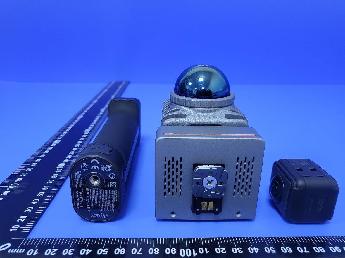
Click to zoom
Application Details
- Equipment Class
- DTS - Digital Transmission System
- Date of Grant
- Feb 19, 2024
- Application Purpose
- Original Equipment
- Date of Application
- Feb 16, 2024
- Equipment Note
- EasyScan M05
- Frequency Range
- 2412.00000000 - 2462.00000000
- Country
- China
Documents & Files
Document Text
Text extracted from the exhibit documents filed with the FCC. Open a document above to read the original.
Users Manual
EasyScan M05 3D Laser Measurement System User Manual Introduction This introduction describes the content, organization, target audience, icon meanings, and reference documents of this manual. Content of the manual The manual primarily focuses on the installation and usage of the M05 3D laser measurement system (referred to as the M05 system hereinafter) hardware devices. Organization of the manual This document consists of the following sections: Chapter Title Content Description Chapter 1 Product Overview Briefly introduce the M05 system and its main technical parameters. Chapter 2 Product Hardware Component Provide a detailed description of the overall structure, interface definitions, and usage constraints of the M05 system. Chapter 3 Device Installation and Disassembly Explain the installation and disassembly methods of each component of the M05 system. Chapter 4 Device Operation Introduction to the operating methods of the M05 system. Chapter 5 Appendix Device usage precaution and troubleshooting Target audience This manual is primarily intended for users familiar with 3D laser measurement and personnel responsible for outdoor data collection. The readers are expected to have knowledge in the following areas: ◼ Traditional surveying techniques ◼ 3D laser measurement technology Icon meanings Icon Meaning Prompt users to pay special attention to the following points during the installation or use of the M05 system. Providing additional information to users. Reference documents The reference documents related to the use of the M05 system include: ◼ <M05 3D Laser Measurement System User Manual>(This document) Warning: Before using the M05 system device, please read the user manual carefully to avoid electric shock or equipment damage due to misuse. Catalog 1 PRODUCT OVERVIEW ..................................................................................... 1 1.1 PRODUCT INTRODUCTION ................................................................................. 1 1.2 MAIN TECHNICAL PARAMETERS ...................................................................... 2 2 PRODUCT HARDWARE COMPONENT ........................................................ 4 2.1 MAIN BODY ..................................................................................................... 4 2.2 BATTERY .......................................................................................................... 5 2.2.1 Device power on ...................................................................................... 6 2.2.2 Device power off ...................................................................................... 6 3 DEVICE INSTALLATION AND DISASSEMBLY .......................................... 7 3.1 PREPARATION BEFORE INSTALLATION ............................................................. 7 3.2 M05 SYSTEM INSTALLATION AND DISASSEMBLY ............................................ 8 3.2.1 Installation of handle battery to the main body ........................................ 8 3.2.2 Disassembly of handle battery from the main body ................................. 9 4. DEVICE OPERATION .................................................................................... 10 4.1 DEVICE START ............................................................................................... 10 4.2 CAMERA OPERATION ..................................................................................... 11 4.3 MAIN BODY CONNECTION ............................................................................. 11 4.3 MAIN BODY SHUTDOWN ................................................................................ 11 4.4 BATTERY CHARGE ......................................................................................... 12 5. APPENDIX ........................................................................................................ 13 5.1 COMMON FAULT DIAGNOSIS .......................................................................... 13 5.2 DEVICE USAGE PRECAUTIONS ........................................................................ 13 1 1 Product Overview 1.1 Product Introduction EasyScan M05 is a portable 3D laser measurement system independently developed by Wuhan Eleph-Print Tech Co., Ltd. It is designed with the concepts of lightweight and user-friendliness, integrating technologies such as multi-line laser LiDAR and image acquisition. It integrates high- precision laser scanners, angle measurement devices, and other sensors. Supported by self-developed time synchronization technology and integrated multi-sensor integration technology with independent intellectual property rights, it can efficiently and easily complete the scanning and acquisition of 3D data. The main applications of the M05 laser measurement system include, but are not limited to, building facade measurement, accident scene investigation, volume calculation of stockpiles, interior decoration, flat layout drawing, and digital parks. 2 Fig 1-1 M05 system 1.2 Main Technical Parameters The main technical parameters of the M05 laser measurement system are shown in the table below: Table 1-1 M05 system main technical parameters table System Parameter Handheld Weight 860g Operating Temperature -10°C - 50°C Storage Temperature -20°C - 60°C Power Consumption 20W(typical value) Power Supply 12V - 17.6V 3 Operating Time 1.5h Storage Capacity 64GB U-disk Platform Handheld Charging Type Type-C Laser Scanning Unit Max. Range 70m Laser Class Class 1 Laser FoV Horizontal 360° Vertical -7° - 52° Laser Wavelength 905nm Scan Speed 200,000pts/s Relative Accuracy 2cm Absolute Accuracy 5cm Camera Unit Camera FoV 360° Panoramic Camera Camera Resolution 18MP 4 2 Product Hardware Component M05 system includes two versions, main difference is the camera. The Basic version consists of the main body, battery, U-disk, and Insta ONE RS dual-lens camera. The PRO version consists of the main body, battery, U-disk, and Insta ONE RS 1-Inch camera. 2.1…
Text truncated - open the document above for the full version.
Cover Letter(s)
Features Wide bandwidth 2.4G&5G WIFI RoHS compliant Applications Dual-band 2.4/5.5 GHz WLAN Specifications Part Number Frequency Range (MHz) Peak Gain Average Gain VSWR Impedance 2.4G&5G-B200 2400~2500 1.0 dBi typ. (XZ-V) -2.5 dBi typ. (XZ-V) 2.2 max. 50 Ω 4900~5875 (YZ-V) -2.5 dBi typ. (YZ-V) 50 2.2 max. Ω Q’ty/Box (pcs) : 100pcs Operating Temperature Range : -40 ~ +85 o C Storage Temperature Range : -40 ~ +85 o C Storage Period : 12 months max. Power Capacity : 2W max. Antenna 1.0 dBi typ. Manufacturer: Wuhan Eleph-Print Tech Co.,Ltd Address: 701, Blk B, Huishang Bldg, 2 Wudayuan Rd, Wuhan, Hubei,China Unit: mm Loss (with matching Return circuits) Radiation Patterns XZ-V/XZ-H YZ-V/YZ-H XY-V/XY-H 180 o 270 o 0 o 90 X Z Y XZ-cut scanning direction 180 o 270 o 0 o 90 o X Z Y YZ-cut scanning direction 180 270 o 0 90 o X Z Y XY-cut scanning direction XZ-V/XZ-H YZ-V/YZ-H XY-V/XY-H 180 270 o 0 90 o X Z Y XY-cut scanning direction 180 o 270 o 0 o 90 X Z Y XZ-cut scanning direction 180 o 270 o 0 o 90 o X Z Y YZ-cut scanning direction
External Photos
Page 1 of 6 Report No.: LGT24A033 Appendix - External Photographs of EUT Constructional Details Model: M05 Photo 1 Photo 2 Page 2 of 6 Report No.: LGT24A033 Photo 3 Photo 4 Page 3 of 6 Report No.: LGT24A033 Photo 5 Photo 6 Page 4 of 6 Report No.: LGT24A033 Photo 7 Photo 8 Page 5 of 6 Report No.: LGT24A033 Photo 9 Photo 10 Page 6 of 6 Report No.: LGT24A033 Photo 11 Photo 12
ID Label/Location Info
Label
Internal Photos
Page 1 of 13 Report No.: LGT24A033 Appendix - Internal Photographs of EUT Constructional Details Model: M05 Photo 1 Photo 2 Page 2 of 13 Report No.: LGT24A033 Photo 3 Photo 4 2.4G ANTENNA 5G ANTENNA 1 5G ANTENNA 2 Page 3 of 13 Report No.: LGT24A033 Photo 5 Photo 6 Page 4 of 13 Report No.: LGT24A033 Photo 7 Photo 8 Page 5 of 13 Report No.: LGT24A033 Photo 9 Photo 10 Page 6 of 13 Report No.: LGT24A033 Photo 11 Photo 12 Page 7 of 13 Report No.: LGT24A033 Photo 13 Photo 14 Page 8 of 13 Report No.: LGT24A033 Photo 15 Photo 16 Page 9 of 13 Report No.: LGT24A033 Photo 17 Photo 18 Page 10 of 13 Report No.: LGT24A033 Photo 19 Photo 20 Page 11 of 13 Report No.: LGT24A033 Photo 21 Photo 22 Page 12 of 13 Report No.: LGT24A033 Photo 23 Photo 24 Page 13 of 13 Report No.: LGT24A033 Photo 25 Photo 26
RF Exposure Info
The test report is effective only with both signature and specialized stamp. This report shall not be reproduced except in full without the written approval of the Laboratory. The results in this report only apply to the tested sample. Shenzhen LGT Test Service Co., Ltd. Tel: 0755-89668180 E-mail:[email protected] Web: www.lgt-cert.com Room 205, Building 13, Zone B, Zhenxiong Industrial Park, No.177, Renmin West Road, Jinsha, Kengzi Street, Pingshan District, Shenzhen, Guangdong, China RF TEST REPORT Product Name: EasyScan M05 Model Name: M05, M05 Pro FCC ID: 2A8YS-M05 Issued For : Wuhan Eleph-Print Tech Co.,Ltd 701, Blk B, Huishang Bldg, 2 Wudayuan Rd, Wuhan, Hubei, China Issued By : Shenzhen LGT Test Service Co., Ltd. Room 205, Building 13, Zone B, Zhenxiong Industrial Park, No.177, Renmin West Road, Jinsha, Kengzi Street, Pingshan District, Shenzhen, Guangdong, China Report Number: LGT24A033HA01 Sample Received Date: Jan. 10, 2024 Date of Test: Jan. 10, 2024 – Jan. 30, 2024 Date of Issue: Jan. 30, 2024 Report No.: LGT23A033HA01 Page 2 of 9 TEST REPORT CERTIFICATION Applicant: Wuhan Eleph-Print Tech Co.,Ltd Address: 701, Blk B, Huishang Bldg, 2 Wudayuan Rd, Wuhan, Hubei,China Manufacturer: Wuhan Eleph-Print Tech Co.,Ltd Address: 701, Blk B, Huishang Bldg, 2 Wudayuan Rd, Wuhan, Hubei,China Product Name: EasyScan M05 Trademark: EPiC Model Name: M05, M05 Pro Sample Status: Normal APPLICABLE STANDARDS STANDARD TEST RESULTS FCC 47 CFR §2.1093 KDB 447498 D01 General RF Exposure Guidance v06 PASS Prepared by: Approved by: Zane Shan Vita Li Engineer Technical Director Report No.: LGT23A033HA01 Page 3 of 9 TABLE OF CONTENTS 1 . GENERAL INFORMATION 5 1.1 GENERAL DESCRIPTION OF THE EUT 5 1.2 TEST LABORATORY 6 2 . FCC 47CFR §2.1093 REQUIREMENT 7 2.1 TEST STANDARDS 7 2.5 TEST RESULT 8 Report No.: LGT23A033HA01 Page 4 of 9 Revision History Rev. Issue Date Revisions 00 Jan. 30 2024 Initial Issue Report No.: LGT23A033HA01 Page 5 of 9 1. GENERAL INFORMATION 1.1 GENERAL DESCRIPTION OF THE EUT Product Name: EasyScan M05 Trademark: EPiC Model Name: M05 Series Model: M05 Pro Model Difference: Only the model name is different. Product Description: Operation Frequency: IEEE 802.11b/g/n(20MHz): 2412~2462MHz IEEE 802.11n(40MHz):2422~2452MHz IEEE 802.11a/n(HT20)/ ac(VHT20)/ax(HE20): 5.180GHz-5.240GHz IEEE 802.11n(HT40)/ ac(VHT40)/ax(HE40): 5.190GHz-5.230GHz IEEE 802.11 ac(VHT80)/ax(HE80): 5.210GHz IEEE 802.11a/n(HT20)/ ac(VHT20)/ax(HE20): 5.260GHz-5.320GHz IEEE 802.11 n(HT40)/ ac(VHT40)/ax(HE40): 5.270GHz-5.310GHz IEEE 802.11 ac(VHT80)/ax(HE80): 5.290GHz IEEE 802.11a/n(HT20)/ ac(VHT20)/ax(HE20): 5.500GHz-5.700GHz IEEE 802.11 n(HT40)/ ac(VHT40)/ax(HE40): 5.510GHz-5.670GHz IEEE 802.11 ac(VHT80)/ax(HE80): 5.530GHz- 5.610GHz I IEEE 802.11a/n(HT20)/ ac(VHT20)/ax(HE20): 5.745GHz-5.825GHz IEEE 802.11a/n(HT40)/ac(VHT40)/ax(HE40): 5.755GHz-5.795GHz IEEE 802.11 ac(VHT80)/ax(HE80): 5.775GHz Modulation Type: 802.11b(DSSS):CCK,DQPSK,DBPSK 802.11g(OFDM):BPSK,QPSK,16-QAM,64-QAM 802.11a(OFDM): BPSK, QPSK, 16-QAM, 64-QAM 802.11n(OFDM): BPSK, QPSK, 16-QAM, 64-QAM 802.11ac (OFDM): BPSK, QPSK, 16-QAM, 64-QAM, 256-QAM 802.11ax(OFDM, OFDMA): BPSK, QPSK, 16-QAM, 64-QAM, 256-QAM, 1024QAM Antenna Designation: FPC Antenna Gain(dBi) 1 More details of EUT technical specification, please refer to the User Manual. Test Channel: Please refer to the Note 3. Rating: Input: DC 12-17.6V Battery: Capacity: 1950mAh Rated Voltage: 15.4V Max Charge Voltage: 12V Report No.: LGT23A033HA01 Page 6 of 9 Max Charge Current: 2A Hardware Version: M05_V1.0.0 Software Version: Easy Point Access M V1.00.00Beta.apk Connecting I/O Port(s): Please refer to the Note 1. 1.2 TEST LABORATORY Company Name: Shenzhen LGT Test Service Co., Ltd. Address: Room 205, Building 13, Zone B, Zhenxiong Industrial Park, No.177, Renmin West Road, Jinsha, Kengzi Street, Pingshan District, Shenzhen, Guangdong, China Accreditation Certificate A2LA Certificate No.: 6727.01 FCC Registration No.: 746540 CAB ID: CN0136 Report No.: LGT23A033HA01 Page 7 of 9 2. FCC 47CFR §2.1093 REQUIREMENT 2.1 TEST STANDARDS RF EXPOSURE EVALUATION METHOD- KDB 447498 D01V06 SAR Test Exclusion Thresholds for 100 MHz – 6 GHz and ≤ 50 mm Approximate SAR Test Exclusion Power Thresholds at Selected Frequencies and Test Separation Distances are illustrated in the following Table. Note: 10-g Extremity SAR Test Exclusion Power Thresholds are 2.5 times higher than the 1-g SAR Test Exclusion Thresholds indicated above. These thresholds do not apply, by extrapolation or other means, to occupational exposure limits. The 1-g and 10-g SAR test exclusion thresholds for 100 MHz to 6 GHz at test separation distances ≤ 50 mm are determined by: [(max. power of channel, including tune-up tolerance, mW)/(min. test separation distance, mm)] · [√f(GHz)] ≤ 3.0 for 1-g SAR and ≤ 7.5 for 10-g extremity SAR,where f(GHz) is the RF channel transmit frequency in GHz Power and distance are rounded to the nearest mW and mm before calculation The result is rounded to one decimal place for comparison The test exclusions are applicable only when the minimum test separation distance is ≤ 50 mm and for transmission frequencies between 100 MHz and 6 GHz. When the minimum test separation distance is < 5 mm, a distance of 5 mm is applied to determine SAR test exclusion. Report No.: LGT23A033HA01 Page 8 of 9 2.5 TEST RESULT Turn up Result Mode Turn up Power 2.4G WIFI-802.11b 5±1dBm 2.4G WIFI-802.11g 5±1dBm 2.4G WIFI-802.11n(HT20) 5±1dBm 2.4G WIFI-802.11n(HT40) 5±1dBm 5G WIFI-802.11a 6±1dBm 5G WIFI-802.11n(HT20) 6±1dBm 5G WIFI-802.11n(HT40) 6±1dBm 5G WIFI-802.11ac(VHT20) 6±1dBm 5G WIFI-802.11ac(VHT40) 6±1dBm 5G WIFI-802.11ac(VHT80) 6±1dBm 5G WIFI-802.11ax(HE20) 6±1dBm 5G WIFI-802.11ax(HE40) 6±1dBm 5G WIFI-802.11ax(HE80) 6±1dBm Report No.: LGT23A033HA01 Page 9 of 9 The result of worst mode: 2.4G WIFI ANT Gain (G) Antenna number: 1 Antenna A gain : 1dBi MIMO technology Directional gain=1dBi (gain of antenna in linear scale=1.259) 2.4G WIFI2.4225.556 3…
Text truncated - open the document above for the full version.
Test Report
The test report is effective only with both signature and specialized stamp. This report shall not be reproduced except in full without the written approval of the Laboratory. The results in this report only apply to the tested sample. Shenzhen LGT Test Service Co., Ltd. Tel: 0755-89668180 E-mail:[email protected] Web: www.lgt-cert.com Room 205, Building 13, Zone B, Zhenxiong Industrial Park, No.177, Renmin West Road, Jinsha, Kengzi Street, Pingshan District, Shenzhen, Guangdong, China RF TEST REPORT Product Name: EasyScan M05 Model Name: M05, M05 Pro FCC ID: 2A8YS-M05 Issued For : Wuhan Eleph-Print Tech Co.,Ltd 701, Blk B, Huishang Bldg, 2 Wudayuan Rd, Wuhan, Hubei, China Issued By : Shenzhen LGT Test Service Co., Ltd. Room 205, Building 13, Zone B, Zhenxiong Industrial Park, No.177, Renmin West Road, Jinsha, Kengzi Street, Pingshan District, Shenzhen, Guangdong, China Report Number: LGT23L113RF06 Sample Received Date: Jan. 10, 2024 Date of Test: Jan. 10, 2024 – Jan. 30, 2024 Date of Issue: Jan. 30, 2024 Report No.: LGT24A033RF06 Page 2 of 69 TEST REPORT CERTIFICATION Applicant: Wuhan Eleph-Print Tech Co.,Ltd Address: 701, Blk B, Huishang Bldg, 2 Wudayuan Rd, Wuhan, Hubei,China Manufacturer: Wuhan Eleph-Print Tech Co.,Ltd Address: 701, Blk B, Huishang Bldg, 2 Wudayuan Rd, Wuhan, Hubei,China Product Name: EasyScan M05 Trademark: EPiC Model Name: M05, M05 Pro Sample Status: Normal APPLICABLE STANDARDS STANDARD TEST RESULTS FCC Part 15.247, Subpart C ANSI C63.10-2013 PASS Prepared by: Approved by: Zane Shan Vita Li Engineer Technical Director Report No.: LGT24A033RF06 Page 3 of 69 Table of Contents Page 1. SUMMARY OF TEST RESULTS 6 1.1 TEST FACTORY 7 1.2 MEASUREMENT UNCERTAINTY 7 2. GENERAL INFORMATION 8 2.1 GENERAL DESCRIPTION OF THE EUT 8 2.2 DESCRIPTION OF THE TEST MODES 10 2.3 TEST SOFTWARE AND POWER LEVEL 10 2.4 DESCRIPTION OF NECESSARY ACCESSORIES AND SUPPORT UNITS 11 2.5 EQUIPMENTS LIST FOR ALL TEST ITEMS 12 3. EMC EMISSION TEST 13 3.1 CONDUCTED EMISSION MEASUREMENT 13 3.2 RADIATED EMISSION MEASUREMENT 17 4. CONDUCTED SPURIOUS & BAND EDGE EMISSION 28 4.1 LIMIT 28 4.2 TEST PROCEDURE 28 4.3 DEVIATION FROM STANDARD 28 4.4 TEST SETUP 28 4.5 EUT OPERATION CONDITIONS 28 4.6 TEST RESULTS 28 5. POWER SPECTRAL DENSITY TEST 29 5.1 LIMIT 29 5.2 TEST PROCEDURE 29 5.3 DEVIATION FROM STANDARD 29 5.4 TEST SETUP 29 5.5 EUT OPERATION CONDITIONS 29 5.6 TEST RESULTS 29 6. BANDWIDTH TEST 30 6.1 LIMIT 30 6.2 TEST PROCEDURE 30 6.3 DEVIATION FROM STANDARD 30 6.4 TEST SETUP 30 6.5 EUT OPERATION CONDITIONS 30 6.6 TEST RESULTS 30 Report No.: LGT24A033RF06 Page 4 of 69 Table of Contents Page 7. PEAK OUTPUT POWER TEST 31 7.1 LIMIT 31 7.2 TEST PROCEDURE 31 7.3 DEVIATION FROM STANDARD 31 7.4 TEST SETUP 31 7.5 EUT OPERATION CONDITIONS 31 7.6 TEST RESULTS 31 8. ANTENNA REQUIREMENT 32 8.1 STANDARD REQUIREMENT 32 8.2 EUT ANTENNA 32 APPENDIX I - TEST RESULTS 33 DUTY CYCLE 33 MAXIMUM PEAK CONDUCTED OUTPUT POWER 38 -6DB BANDWIDTH 39 OCCUPIED CHANNEL BANDWIDTH 44 MAXIMUM POWER SPECTRAL DENSITY LEVEL 49 BAND EDGE 54 CONDUCTED RF SPURIOUS EMISSION 61 Report No.: LGT24A033RF06 Page 5 of 69 Revision History Rev. Issue Date Contents 00 Jan. 30, 2024 Initial Issue Report No.: LGT24A033RF06 Page 6 of 69 1. SUMMARY OF TEST RESULTS Test procedures according to the technical standards: KDB 558074 D01 15.247 Meas Guidance v05r02. FCC Part 15.247,Subpart C Standard Section Test Item Judgment Remark 15.207 Conducted Emission PASS -- 15.247 (a)(2) 6dB Bandwidth PASS -- 15.247 (b)(3) Output Power PASS -- 15.209 Radiated Spurious Emission PASS -- 15.247 (d) Conducted Spurious & Band Edge Emission PASS -- 15.247 (e) Power Spectral Density PASS -- 15.205 Restricted Band Edge Emission PASS -- Part 15.247(d)/ Part 15.209(a) Band Edge Emission PASS -- 15.203 Antenna Requirement PASS -- NOTE: (1) ‘N/A’ denotes test is not applicable in this Test Report. (2) All tests are according to ANSI C63.10-2013. Report No.: LGT24A033RF06 Page 7 of 69 1.1 TEST FACTORY Company Name: Shenzhen LGT Test Service Co., Ltd. Address: Room 205, Building 13, Zone B, Zhenxiong Industrial Park, No.177, Renmin West Road, Jinsha, Kengzi Street, Pingshan District, Shenzhen, Guangdong, China Accreditation Certificate A2LA Certificate No.: 6727.01 FCC Registration No.: 746540 CAB ID: CN0136 1.2 MEASUREMENT UNCERTAINTY The reported uncertainty of measurement y ± U, where expended uncertainty U is based on a standard uncertainty multiplied by a coverage factor of k=2, providing a level of confidence of approximately 95 %. No. Item Uncertainty 1 RF Output Power, Conducted ±0.71dB 2 Power Spectral Density, Conducted ±1.57 dB 3 Unwanted Emission, Conducted ±0.63dB 4 Conducted emission ±2.80dB 5 All Emissions, Radiated (0.009-30MHz) ±2.16dB 6 All Emissions, Radiated (30MHz-1GHz) ±4.40dB 7 All Emissions, Radiated (1GHz-18GHz) ±5.49dB Note: The measurement uncertainty is not included in the test result. Report No.: LGT24A033RF06 Page 8 of 69 2. GENERAL INFORMATION 2.1 GENERAL DESCRIPTION OF THE EUT Product Name: EasyScan M05 Trademark: EPiC Model Name: M05 Series Model: M05 Pro Model Difference: Only the model name is different. Product Description: Operation Frequency: 802.11b/g/n(20MHz): 2412~2462MHz 802.11n(40MHz):2422~2452MHz Modulation Type: 802.11b(DSSS):CCK,DQPSK,DBPSK 802.11g(OFDM):BPSK,QPSK,16-QAM,64-QAM 802.11n(OFDM):BPSK,QPSK,16-QAM,64-QAM Number of Channel: 802.11b/g/n: 11CH 802.11n: 7CH Antenna Designation: FPC Antenna Gain(dBi): 1 Channel List: Please refer to the Note 3. Rating: Input: DC 12-17.6V Battery: Capacity: 1950mAh Rated Voltage: 15.4V Max Charge Voltage: 12V Max Charge Current: 2A Hardware Version: M05_V1.0.0 Software Version: Easy Point Access M V1.00.00Beta.apk Connecting I/O Port(s): Please refer to the Note 1. Note: 1. For a more detailed features description, please refer to the manufacturer’s specifications or the User Manual. 2. The antenna information refers to the manufacturer provide report, applicable only to the tested sample identified in th…
Text truncated - open the document above for the full version.
Test Setup Photos
Page 1 of 2 Report No.: LGT24A033 Appendix - Test Setup photos Set-up for Radiated Spurious Emission, Below 1GHz Set-up for Radiated Spurious Emission, Above 1GHz Page 2 of 2 Report No.: LGT24A033 Set-up for Conducted Emission
Contact Information
Applicant
Yuan dewen
Technical Contact
Test Firm
Shenzhen LGT Test Service Co., Ltd.Wen Wen
[email protected]0755-89668180
Technical Specifications
| # | Rule Parts | Frequency Range | Power Output |
|---|---|---|---|
| 1 | 15C | 2.41 GHz - 2.46 GHz | 3.55 mW |
Other Applications from Wuhan Eleph-Print Tech Co.,Ltd
2A8YS-T150
Jul 24, 20263D Laser Scanner
Equipment Class
NII - Unlicensed National Information Infrastructure TX
2A8YS-X10
May 05, 2023Airborne LiDAR
Equipment Class
DTS - Digital Transmission System