2A8YS-X10Airborne LiDAR
Wuhan Eleph-Print Tech Co.,Ltd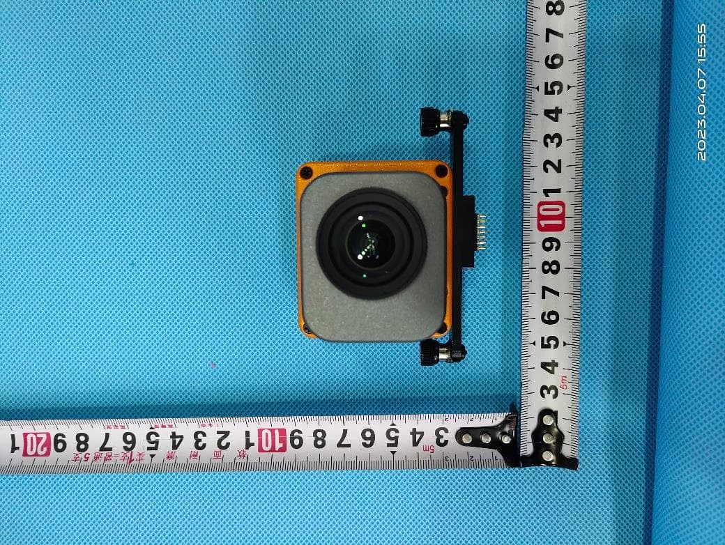
Click to zoom
Application Details
- Equipment Class
- DTS - Digital Transmission System
- Date of Grant
- May 05, 2023
- Application Purpose
- Original Equipment
- Date of Application
- May 05, 2023
- Equipment Note
- Airborne LiDAR
- Frequency Range
- 2412.00000000 - 2462.00000000
- Country
- China
Documents & Files
Document Text
Text extracted from the exhibit documents filed with the FCC. Open a document above to read the original.
Users Manual
EasyScan TM X10 Airborne LiDAR Measurement System Product Manual Catalog 1 PRODUCT INTRODUCTION ........................................................................... 2 1.1 PRODUCT OVERVIEW ....................................................................................... 2 1.2 MAIN TECHNICAL PARAMETERS ...................................................................... 2 2 PRODUCT COMPOSITION .............................................................................. 4 2.1 MAIN BODY AND AERIAL METRIC CAMERA .................................................... 4 2.2 SKYPORT ADAPTOR ...................................................................................... 5 2.3 ANTENNA COMPONENT .................................................................................... 5 2.4 HIGH-CAPACITY USB-DISK .............................................................................. 5 3 EQUIPMENT INSTALLATION AND DISASSEMBLY ................................. 6 3.1 PREPARATION BEFORE INSTALLATION ............................................................. 6 3.2 X10 SYSTEM INSTALLATION AND DISASSEMBLY ............................................. 6 3.2.1Aerial metric camera installation and disassembly ................................... 7 3.2.2 SKYPORT adaptor installation and disassembly ..................................... 7 3.2.3 High-capacity USB-disk installation ........................................................ 8 3.2.4 Main body installation and disassembly ................................................... 9 3.2.5 Antenna component installation and disassembly .................................. 10 4 EQUIPMENT OPERATION ............................................................................ 11 4.1 EQUIPMENT START ......................................................................................... 11 4.2 MAIN BODY CONNECTION ............................................................................. 11 4.3 MAIN BODY SHUTDOWN ................................................................................ 12 5 DATA COLLECTION ....................................................................................... 12 5.1 CLIENT INSTALLATION ................................................................................... 12 5.2 FLIGHT PLANNING .......................................................................................... 15 5.2.1 Create flight mode .................................................................................. 15 5.2.2 Import KML ........................................................................................... 22 5.3 EQUIPMENT CONTROL ...................................................................................... 1 5.3.3 Software interface .................................................................................... 1 5.3.4 Data collection ......................................................................................... 4 6 APPENDIX ........................................................................................................... 7 6.1 ROUTINE MAINTENANCE .................................................................................. 7 1 Product Introduction 1.1 Product Overview EasyScanTM X10 airborne LiDAR measurement system, is a portable 3D laser measurement system independently developed by Wuhan Eleph-Print Tech Co.,Ltd, it integrates LiDAR module, high-precision inertial navigation module and other modules, has the characteristics of high precision, high frequency, multi echo and so on. The weight and volume are extremely lowered, making the overall weight less than 1.15kg(aerial metric camera and other components not included), greatly improving the endurance of the drone. The system is equipped with modular aerial metric camera, which can be flexible matched according to actual needs. SKYPORT and other customized interfaces are available, which are compatible with DJI M300RTK and other customized drones. LiDAR control is embedded into the UAV control unit, combined with point cloud and image intelligent photogrammetry parameter algorithm, simple flight planning, greatly reducing the threshold of use. Real-time point cloud display, to understand the ground features condition anytime and anywhere, to improve the timeliness of data. Integrated storage design of laser data and orthophoto, efficient combination of image and point cloud, reducing manual intervention and improving data registration accuracy. X10 could be widely used in the fields like power line inspection, topographic mapping, agricultural and forestry survey, open-pit mine survey, disaster monitoring and other industries, to meet the data collection requirement of different application scenarios. 1.2 Main Technical Parameters Main technical parameters of X10 laser measurement system are shown in the table below: Table 1-1 X10 system main technical parameter Item Parameter X10 System Parameter Weight① 1260±10g Dimension ca. L159 W118 D127 (mm) System Consumption 25w(typical value) Power Supply 10~30VDC Device Interface DJI skyport/other interface available upon request Data Storage 256GB U-disk Operating Temperature -10°C to 50°C Storage Temperature -30°C to 60°C System Accuracy 5cm Compatible Platform DJI M300 Other UAV models Laser Scanning Unit Scanning Principle Mechanic Rotation Mirror Laser Class Class I Wavelength 905nm Measurement Range 120m@60% reflectivity (all channel) Ranging Accuracy② 0.5cm Horizontal FoV 360° Vertical FoV 30°(-15°~ +15°) Scanning Point Frequency Single Echo: 320000pts/s Dual Echo: 640000pts/s Echo Mode Single Echo/Dual Echo IMU Unit GNSS Signal Tracking BDS,GPS,GLONASS, Galileo Positioning Accuracy (post- processing) Plane: 1cm Elevation: 2cm Position Data Rate 5HZ Attitude Accuracy (post- processing) heading:0.05° pitch/roll:0.01° Attitude Data Rate 200HZ Aerial Metric Camera Unit (modular) Effective Pixels 26MP Sensor Dimension 23.5×15.7mm Image Resolution 6252×4168 Image …
Text truncated - open the document above for the full version.
Cover Letter(s)
Model Confirmation Letter We,Wuhan Eleph-Print Tech Co.,Ltd Product Name:Airborne LiDAR Model No.:X10, X10+, R3, R3PRO We declare that Model X10+, R3, R3PRO have same working principles & PCB Board & block diagram & operating principle as the certified prototype of model X10. They’re only have different colors in appearance. Company Name:Wuhan Eleph-Print Tech Co.,Ltd Date:2023/4/27 Signture:
Cover Letter(s)
Wuhan Eleph-Print Tech Co.,Ltd 2023.4.27 Eurofins Electrical and Electronic Testing NA, Inc. 914 West Patapsco Avenue Baltimore, MD 21230 RE: LETTER OF AGENT AUTHORIZATION To Whom It May Concern: We, the undersigned, hereby authorize (Shenzhen LGT Test Service Co., Ltd.) to act on our behalf in all matters relating to application for equipment authorization, including the signing of all documents relating to these matters. We also hereby certify that no party to the application authorized hereunder is subject to the denial of benefits, including FCC benefits, pursuant to Section 5301 of the Anti-Drug Abuse Act of 1988, 21 U.S.C.853(a). This agreement expires one year from the current date. Sincerely, Signature: Date: 2023. 04.27 Name: Wenwen Title: Manager Company: Wuhan Eleph-Print Tech Co.,Ltd
Cover Letter(s)
Long-Term Confidentiality Request Letter For Certification Service in the USA Federal Communication Commission Equipment Authorization Division, Application Processing Branch 7435 Oakland Mills Road Columbia, MD 21048 To whom it may concern Pursuant to Paragraphs §0.457 and 0.459 of the Commission’s Rules (47 C.F.R.) and Section §552(b)(4) of the Freedom of Information Act, we request confidentiality for the documentation of the following products: FCC ID Model name 2A8YS-X10 X10, X10+, R3, R3PRO For the products listed above, we request permanent confidentiality for all applicable exhibits as there are: • the Operational Description • the Block Diagram • the Schematics • the Parts Lists The above listed exhibits contain trade secrets and proprietary information that could be of benefit to our competitors. If you have any questions, please feel free to contact us at the address shown below. Sincerely, Signature Date2023.04.27 Printed Name of Signee:Wenwen Company:Wuhan Eleph-Print Tech Co.,Ltd Address:701, Blk B, Huishang Bldg, 2 Wudayuan Rd, Wuhan, Hubei,China Phone:027-8795 9978 Fax:027-8795 9978 Email: [email protected]
External Photos
Page 1 of 9 Report No.: LGT23D038 Appendix - External Photographs of EUT Constructional Details FCC ID: 2A8YS-X10 Model: X10 Host Photo 1 Photo 2 Page 2 of 9 Report No.: LGT23D038 Photo 3 Photo 4 Page 3 of 9 Report No.: LGT23D038 Photo 5 Photo 6 Page 4 of 9 Report No.: LGT23D038 Photo 7 Host camera Photo 8 Page 5 of 9 Report No.: LGT23D038 Photo 9 Photo 10 Page 6 of 9 Report No.: LGT23D038 Photo 11 Photo 12 Page 7 of 9 Report No.: LGT23D038 Photo 13 UAV rack Photo 14 Page 8 of 9 Report No.: LGT23D038 Photo 15 Photo 16 Page 9 of 9 Report No.: LGT23D038 Photo 17 GNSS Antenna Photo 18
ID Label/Location Info
Label Airborne LiDAR Model:X10 FCC ID:2A8YS-X10
Internal Photos
Page 1 of 8 Report No.: LGT23D038 Appendix - Internal Photographs of EUT Constructional Details FCC ID: 2A8YS-X10 Model: X10 Host Photo 1 Photo 2 Page 2 of 8 Report No.: LGT23D038 Photo 3 GNSS Module Photo 4 Page 3 of 8 Report No.: LGT23D038 Photo 5 Photo 6 Page 4 of 8 Report No.: LGT23D038 Photo 7 Photo 8 Page 5 of 8 Report No.: LGT23D038 Photo 9 Photo 10 Page 6 of 8 Report No.: LGT23D038 Photo 11 Photo 12 Page 7 of 8 Report No.: LGT23D038 Photo 13 Host camera Photo 14 Page 8 of 8 Report No.: LGT23D038 Photo 15
RF Exposure Info
RF Exposure Report FCC-ID:2A8YS-X10 RF Exposure Measurement The limit for Maximum Permissible Exposure (MPE) specified in FCC 1.1310 is followed. The gain of the antennas used in the product is extracted from the Antenna data sheets provided and also the maximum total power input to the antenna is measured. Through the Friis transmission formula and the maximum gain of the antenna, we can calculate the distance, away from the product, where the limit of MPE is reached. Although the Friis Transmission formula is far field assumption, the calculated result of that is an over- prediction for near field power density. It is taken as worst case to specify the safety range. RF Exposure Limit According to FCC 1.1310: The criteria listed in the following table shall be used to evaluate the environmental impact of the human exposure to radio-frequency (RF) radiation as specified in 1.1307 (b) Limits for Maximum Permissible Exposure (MPE) F= Frequency in MHz Friss Formula Friss Transmission Formula: Pd = (Pout * G) / (4*pi*r²) Where Pd = power density in mW/cm² Pout = output power to antenna in mW G = gain of antenna in linear scale Pi = 3.1416 R = Distance between observation point and the center of radiator in cm If we know the maximum gain of the antenna and the total output power to the antenna, through calculation, we will know MPE value at distance 20cm. EUT Operation condition EUT was enabled to transmit and receive at lowest, middle and highest channels. Classification The antenna of this product, under normal use condition, is at least 20cm away from the body of the user. Warning statement to the user for keeping at least 20cm or more separation distance from the antenna should be included in the User manual. So, this device is classified as Mobile device. Frequency Range (MHz) Electric Field Strength (V/m) Magnetic Field Strength (A/m) Power Density (mW/cm²) Limits for Occupational / controlled Exposures 300 - 1500 -- -- F/300 1500 – 100000 -- -- 5.0 Limits for General population / Uncontrolled Exposure 300 - 1500 -- -- F/1500 1500 – 100000 -- -- 1.0 2.4 WIFI Mode 802.11b/g/n (20MHz): 2412~2462 MHz 802.11n (40MHz):2422~2452MHz Detector PEAK 802.11b 18±1dBm 802.11g 17.5±1dBm 802.11n20 17.5±1dBm 802.11n40 17.5±1dBm ANT Gain (G) Antenna number: 1 Antenna gain:0dBi 802.11b 1 2462 19 79.4328 0.01581 1 802.11g 1 2462 18.5 70.7946 0.01409 1 802.11n20 1 2412 18.5 70.7946 0.01409 1 802.11n40 1 2437 18.5 70.7946 0.01409 1 Power Density (mW/cm²) Limit (mW/cm²) ANT Gain(gain of antenna in linear scale) Protocol Channel Frequency (MHz) Output Power to Antenna (dBm) Output Power to Antenna (mW)
Test Report
Antenna Spec Antenna dexcribe: Antenna plate: PCB Antenna Model name: X10 Antenna gain: 0 dBi(Max.) Frequency range: 2.4GHZ–2.5GHZ Connector type: direct Manufacture: Wuhan Eleph-Print Tech Co.,Ltd Manufacture Address: 701, Blk B, Huishang Bldg, 2 Wudayuan Rd, Wuhan, Hubei, China 1. Antenna Radiation Patter Gain(dBi) Freq(MHz) Max Min Avg 2400 -1.73178 -3.00815 -8.48713 2450 0 -3.85605 -7.88012 2500 -0.685586 -24.0318 -6.79139
Test Report
The test report is effective only with both signature and specialized stamp. This report shall not be reproduced except in full without the written approval of the Laboratory. The results in this report only apply to the tested sample. Shenzhen LGT Test Service Co., Ltd. Tel: 0755-89668180 E-mail:[email protected] Web: www.lgt-cert.com Room 205, Building 13, Zone B, Chen Hsong Industrial Park, No.177 Renmin West Road, Jinsha Community, Kengzi Street, Pingshan New District, Shenzhen, China RF TEST REPORT Product Name: Airborne LiDAR Model Name: X10, X10+, R3, R3PRO FCC ID: 2A8YS-X10 Issued For : Wuhan Eleph-Print Tech Co.,Ltd 701, Blk B, Huishang Bldg, 2 Wudayuan Rd, Wuhan, Hubei, China Issued By : Shenzhen LGT Test Service Co., Ltd. Room 205, Building 13, Zone B, Chen Hsong Industrial Park, No.177 Renmin West Road, Jinsha Community, Kengzi Street, Pingshan New District, Shenzhen, China Report Number: LGT23D038RF02 Sample Received Date: Apr. 11, 2023 Date of Test: Apr. 11, 2023 – Apr. 24, 2023 Date of Issue: Apr. 24, 2023 Report No.: LGT23D038RF02 Page 2 of 73 TEST REPORT CERTIFICATION Applicant: Wuhan Eleph-Print Tech Co.,Ltd Address: 701, Blk B, Huishang Bldg, 2 Wudayuan Rd, Wuhan, Hubei, China Manufacturer: Wuhan Eleph-Print Tech Co.,Ltd Address: 701, Blk B, Huishang Bldg, 2 Wudayuan Rd, Wuhan, Hubei, China Factory: Wuhan Eleph-Print Tech Co.,Ltd Address: 701, Blk B, Huishang Bldg, 2 Wudayuan Rd, Wuhan, Hubei, China Product Name: Airborne LiDAR Trademark: EPiC Model Name: X10, X10+, R3, R3PRO Sample Status: Normal APPLICABLE STANDARDS STANDARD TEST RESULTS FCC Part 15.247, Subpart C ANSI C63.10-2013 PASS Prepared by: Approved by: Zane Shan Vita Li Engineer Technical Director Report No.: LGT23D038RF02 Page 3 of 73 Table of Contents Page 1. SUMMARY OF TEST RESULTS 6 1.1 TEST FACTORY 7 1.2 MEASUREMENT UNCERTAINTY 7 2. GENERAL INFORMATION 8 2.1 GENERAL DESCRIPTION OF THE EUT 8 2.2 DESCRIPTION OF THE TEST MODES 10 2.3 TEST SOFTWARE AND POWER LEVEL 11 2.4 TABLE OF PARAMETERS OF TEST SOFTWARE SETTING 11 2.5 EQUIPMENTS LIST FOR ALL TEST ITEMS 12 3. EMC EMISSION TEST 13 3.1 CONDUCTED EMISSION MEASUREMENT 13 3.2 RADIATED EMISSION MEASUREMENT 17 4. CONDUCTED SPURIOUS & BAND EDGE EMISSION 28 4.1 LIMIT 28 4.2 TEST PROCEDURE 28 4.3 DEVIATION FROM STANDARD 28 4.4 TEST SETUP 28 4.5 EUT OPERATION CONDITIONS 28 4.6 TEST RESULTS 28 5. POWER SPECTRAL DENSITY TEST 29 5.1 LIMIT 29 5.2 TEST PROCEDURE 29 5.3 DEVIATION FROM STANDARD 29 5.4 TEST SETUP 29 5.5 EUT OPERATION CONDITIONS 29 5.6 TEST RESULTS 29 6. BANDWIDTH TEST 30 6.1 LIMIT 30 6.2 TEST PROCEDURE 30 6.3 DEVIATION FROM STANDARD 30 6.4 TEST SETUP 30 6.5 EUT OPERATION CONDITIONS 30 6.6 TEST RESULTS 30 Report No.: LGT23D038RF02 Page 4 of 73 Table of Contents Page 7. PEAK OUTPUT POWER TEST 31 7.1 LIMIT 31 7.2 TEST PROCEDURE 31 7.3 DEVIATION FROM STANDARD 31 7.4 TEST SETUP 31 7.5 EUT OPERATION CONDITIONS 31 7.6 TEST RESULTS 31 8. ANTENNA REQUIREMENT 32 8.1 STANDARD REQUIREMENT 32 8.2 EUT ANTENNA 32 APPENDIX I:TEST RESULTS 33 DUTY CYCLE 33 MAXIMUM PEAK CONDUCTED OUTPUT POWER 38 -6DB BANDWIDTH 43 OCCUPIED CHANNEL BANDWIDTH 48 MAXIMUM POWER SPECTRAL DENSITY LEVEL 53 BAND EDGE 58 CONDUCTED RF SPURIOUS EMISSION 65 Report No.: LGT23D038RF02 Page 5 of 73 Revision History Rev. Issue Date Contents 00 Apr. 24, 2023 Initial Issue Report No.: LGT23D038RF02 Page 6 of 73 1. SUMMARY OF TEST RESULTS Test procedures according to the technical standards: KDB 558074 D01 15.247 Meas Guidance v05r02. FCC Part 15.247,Subpart C Standard Section Test Item Judgment Remark 15.207 Conducted Emission PASS -- 15.247 (a)(2) 6dB Bandwidth PASS -- 15.247 (b)(3) Output Power PASS -- 15.209 Radiated Spurious Emission PASS -- 15.247 (d) Conducted Spurious & Band Edge Emission PASS -- 15.247 (e) Power Spectral Density PASS -- 15.205 Restricted Band Edge Emission PASS -- Part 15.247(d)/ Part 15.209(a) Band Edge Emission PASS -- 15.203 Antenna Requirement PASS -- NOTE: (1) ‘N/A’ denotes test is not applicable in this Test Report. (2) All tests are according to ANSI C63.10-2013. Report No.: LGT23D038RF02 Page 7 of 73 1.1 TEST FACTORY Company Name: Shenzhen LGT Test Service Co., Ltd. Address: Room 205, Building 13, Zone B, Chen Hsong Industrial Park, No.177 Renmin West Road, Jinsha Community, Kengzi Street, Pingshan New District, Shenzhen, China Accreditation Certificate A2LA Certificate No.: 6727.01 FCC Registration No.: 746540 CAB ID: CN0136 1.2 MEASUREMENT UNCERTAINTY The reported uncertainty of measurement y ± U, where expended uncertainty U is based on a standard uncertainty multiplied by a coverage factor of k=2, providing a level of confidence of approximately 95 %. Parameter Uncertainty Occupied Channel Bandwidth ±3.2 % RF Output Power, Conducted ±0.71dB Power Spectral Density, Conducted ±1.57 dB Unwanted Emission, Conducted ±0.63dB Conducted emission ±2.80dB All Emissions, Radiated (0.009-30MHz) ±2.16dB All Emissions, Radiated (30MHz-1GHz) ±4.40dB All Emissions, Radiated (1GHz-18GHz) ±5.49dB Temperature ±0.5°C Humidity ±2% Duty Cycle ±2.3% Report No.: LGT23D038RF02 Page 8 of 73 2. GENERAL INFORMATION 2.1 GENERAL DESCRIPTION OF THE EUT Product Name: Airborne LiDAR Trademark: EPiC Model Name: X10 Series Model: X10+, R3, R3PRO Model Difference: Only the appearance color is different, the other same. Product Description: The EUT is a Airborne LiDAR Operation Frequency: 802.11b/g/n (20MHz): 2412~2462 MHz 802.11n (40MHz):2422~2452MHz Modulation Type: 802.11b(DSSS):CCK,DQPSK,DBPSK 802.11g(OFDM):BPSK,QPSK,16-QAM,64-QAM 802.11n(OFDM):BPSK,QPSK,16-QAM,64-QAM Number of Channel: 802.11b/g/n/ac (20MHz): 11CH 802.11n/ac (40MHz): 7CH Antenna Designation: PCB Antenna Antenna Gain(dBi): 0dBi Duty Cycle: >98% Channel List: Please refer to the Note 2. Adapter: Model: APS-KI018WE-G Input: AC 100-240V, 50/60Hz, 1.5A Max Output: TYPE-C DC 5V/9V/12V/15V, 3A; DC 20V, 3.25A USB DC 4.5V/5A,5V/4.5A,5V/9V/12V,3A;20V/2.25A Battery: Capacity: 27000mAh Rated Voltage: 20V Hardware Version: X10_V1.0.0 Software Version: …
Text truncated - open the document above for the full version.
Test Setup Photos
Page 1 of 2 Report No.: LGT23D038 Appendix - Test Setup photos Radiated Spurious Emission Test Setup Photo - Below 1GHz Radiated Spurious Emission Test Setup Photo - Above 1GHz Page 2 of 2 Report No.: LGT23D038 Conducted Emission Test Setup Photo
Contact Information
Applicant
Yuan dewen
Test Firm
Shenzhen LGT Test Service Co., Ltd.Wen Wen
[email protected]0755-89668180
Technical Specifications
| # | Rule Parts | Frequency Range | Power Output |
|---|---|---|---|
| 1 | 15C | 2.41 GHz - 2.46 GHz | 72.44 mW |
Other Applications from Wuhan Eleph-Print Tech Co.,Ltd
2A8YS-T150
Jul 24, 20263D Laser Scanner
Equipment Class
NII - Unlicensed National Information Infrastructure TX
2A8YS-M05
Feb 19, 2024EasyScan M05
Equipment Class
DTS - Digital Transmission System