2A8ZSU100OHDU100 Remote Camera Assistant
Zhongshan Yueguang Intelligent Imaging Technology Co., Ltd.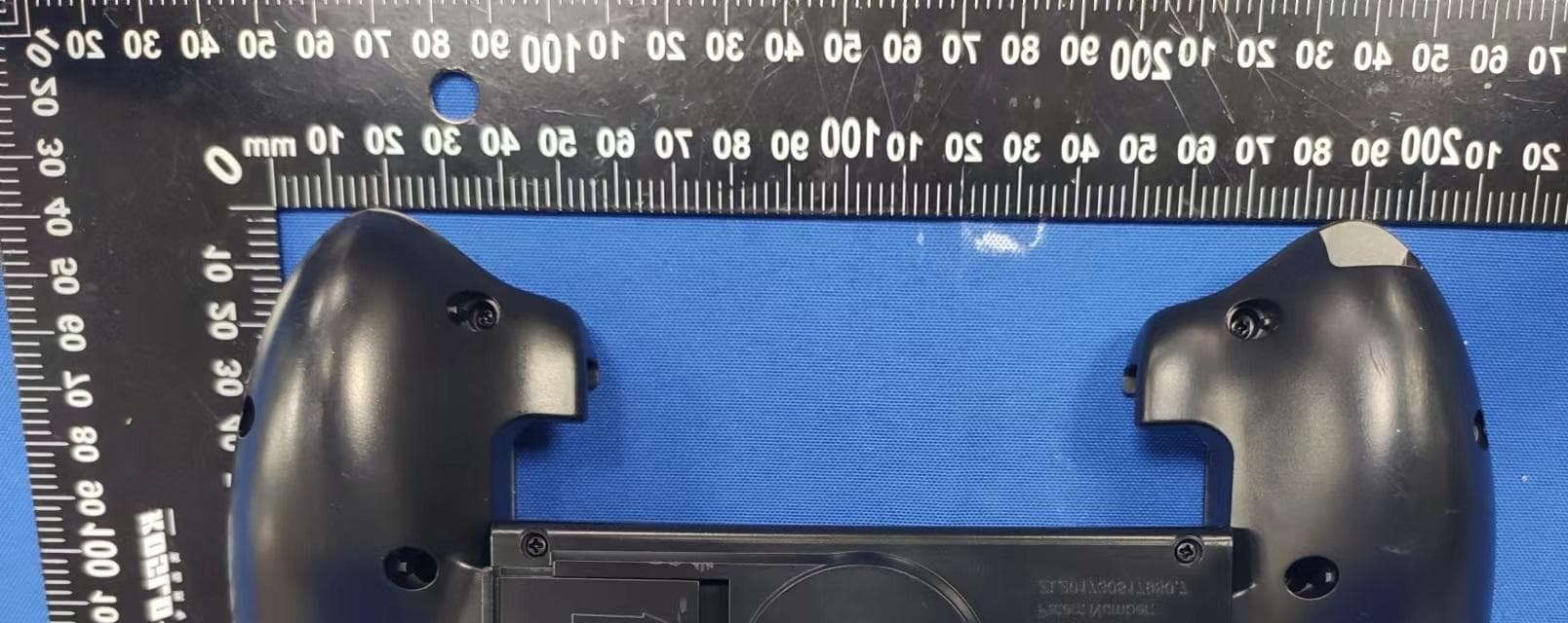
Click to zoom
Application Details
- Equipment Class
- DTS - Digital Transmission System
- Date of Grant
- May 12, 2023
- Application Purpose
- Original Equipment
- Date of Application
- May 12, 2023
- Equipment Note
- U100 Remote Camera Assistant
- Frequency Range
- 2402.00000000 - 2480.00000000
- Country
- China
Documents & Files
Document Text
Text extracted from the exhibit documents filed with the FCC. Open a document above to read the original.
Users Manual
Canon Version November 30, 2021 U100 U100 Remote Camera Assistant Installation and use manual U100 installation & use manual Thank you, dear owner, for using Ueleret U100 Remote Camera Assistant. We will be happy to serve you. This product can remotely operate the camera and intelligent Gimbal. It can be operated within a distance of 0-500 meters without blocking or slightly blocking the transmission signal at both ends. In order to ensure the smooth use of the Remote Camera Assistant products, the owner needs to read the manual carefully and master the operation and inspection methods. We do not recommend the use of this product for people who have just purchased a camera to learn photography for the first time: - Camera functions need to be familiar with, as well as the adjustment of exposure parameters, how to be considered the best results, the photographer needs to hold the camera for a long time to shoot to become proficient and deep understanding. Beginners directly through the remote tablet software interface to operate the camera, the understanding of the use of the camera and how to take a good picture of the understanding takes a long time. - Users who know all the functions and parameters of the camera and have a deeper understanding of exposure, using the U100 Remote Camera Assistant is like putting on the wings of flight. U100 Remote Camera Assistant product use schematic Signal transmitter battery (at the bottom) U100 installation & use manual For the sake of brevity in the instructions and for easy memorization, the following terms may be abbreviated as follows: Name: Abbreviations: Remote camera Assistant Intelligent Gimbal RCA IGb within 500m (Signal unobstructed o r lightly obscured) U100 installation & use manual Content Chapter 1 Applicability Description 1 Chapter 2 Introduction to Remote Camera Assistant2 The value that U100 Remote Camera Assistant brings to the owner. ...................... 2 13 characteristics of U100 Remote Camera Assistant .................................................... 2 Especially suitable shooting scenes and conditions .................................................... 3 Unsuitable scenes and conditions. ................................................................................ 5 STAY, is the conventional way of ecological photography ........................................ 5 Chapter 3 Introduction of Product Structure and Components 11 Schematic diagram of the use of smart photographer products. ................................... 6 Intelligent Gimbal structure diagram. .......................................................................... 6 Main control box interface function. ............................................................................ 10 Function introduction of RCA parts. ........................................................................... 10 Recommended products. ............................................................................................. 20 Chapter 4 Installation of Smart Camera Products 21 Prepare in advance, check the objects, and pack them neatly (strongly recommended, to develop a habit) ...................................................................................................... 21 Investigation and selection of the shooting scene (strongly recommended, to develop a habit) ........................................................................................................................ 22 Intelligent Gimbal installation steps. ........................................................................... 22 A. Installation of smart pan/tilt on hard ground 1. The shooting azimuth mount is mounted on a tripod. ............................................. 22 2.Intelligent Gimbal mounted in the shooting orientation pedestal ............................... 23 3. Install the Lens zoom controller ................................................................................................. 26 4.Install the zoom ring on the zoom lens of the camera (if it is installed before departure, this action is not necessary,For specific installation methods, please refer to the zoom ring installation on page P19) ............................................................................ 27 5.Install the camera on intelligent Gimbal ........................................................................... 27 6.Install the camera battery adapter (if you use the camera's own battery, this step is not necessary . Specific reference please see page P14-P16 to install the camera battery adapter). .................................................................................................................................... 2 8 7. Install the Auxiliary Targeting Viewfinder component. ............................................... 29 8. Bundle the cable components on the main control box of intelligent Gimbal .......... 32 U100 installation & use manual 9.Insert the connections one by one according to the markings on the main control board. ............................................................................................................................. 33 10.Connect the two omni directional antennas to the corresponding ports of the smart pan/tilt. .......................................................................................................................... 36 11. Adjust the camera balance again. ............................................................................. 36 12.Snap the Lens zoom controller with the zoom ring gear installed on the camera lens tightly (ifIf the fixed focus lens is not equipped with the Lens zoom controller, this action is not necessary). .............................................................................................. 38 13. Press the power switch to power on. ........................................................................ 39 B. Smart pan/tilt is installed on the surface of the water and muddy pl…
Text truncated - open the document above for the full version.
External Photos
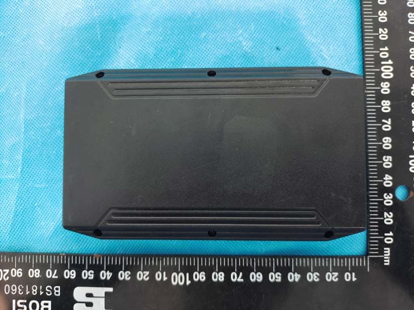
Shenzhen Accurate Technology Co., Ltd. Project No.: SZNS1220815-37100E-RF Page 1 of 4 External Photos Shenzhen Accurate Technology Co., Ltd. Project No.: SZNS1220815-37100E-RF Page 2 of 4 Shenzhen Accurate Technology Co., Ltd. Project No.: SZNS1220815-37100E-RF Page 3 of 4 Shenzhen Accurate Technology Co., Ltd. Project No.: SZNS1220815-37100E-RF Page 4 of 4
Internal Photos
Shenzhen Accurate Technology Co., Ltd. Project No.: SZNS1220815-37100E-RF Page 1 of 9 Internal photos Shenzhen Accurate Technology Co., Ltd. Project No.: SZNS1220815-37100E-RF Page 2 of 9 Shenzhen Accurate Technology Co., Ltd. Project No.: SZNS1220815-37100E-RF Page 3 of 9 Shenzhen Accurate Technology Co., Ltd. Project No.: SZNS1220815-37100E-RF Page 4 of 9 Shenzhen Accurate Technology Co., Ltd. Project No.: SZNS1220815-37100E-RF Page 5 of 9 Shenzhen Accurate Technology Co., Ltd. Project No.: SZNS1220815-37100E-RF Page 6 of 9 ANT Shenzhen Accurate Technology Co., Ltd. Project No.: SZNS1220815-37100E-RF Page 7 of 9 Shenzhen Accurate Technology Co., Ltd. Project No.: SZNS1220815-37100E-RF Page 8 of 9 Shenzhen Accurate Technology Co., Ltd. Project No.: SZNS1220815-37100E-RF Page 9 of 9
RF Exposure Info
Shenzhen Accurate Technology Co., Ltd. Report No.: SZNS1220815-37100E-RF Version 11: 2021-11-09 Page 13 of 37 FCC-BLE FCC §1.1307 (b) & §2.1093 – RF EXPOSURE Applicable Standard According to FCC §2.1093 and §1.1307(b), systems operating under the provisions of this section shall be operated in a manner that ensure that the public is not exposed to radio frequency energy level in excess of the Commission’s guideline. According to KDB 447498 D04 Interim General RF Exposure Guidance v01, clause 2.1.2 – 1- mW test Exemption: Per § 1.1307(b)(3)(i)(A), a single RF source is exempt RF device (from the requirement to show data demonstrating compliance to RF exposure limits, as previously mentioned) if the available maximum time-averaged power is no more than 1 mW, regardless of separation distance. This exemption applies to all operating configurations and exposure conditions, for the frequency range 100 kHz to 100 GHz, regardless of fixed, mobile, or portable device exposure conditions. This is a standalone exemption, and it cannot be applied in conjunction with any other test exemption. Test Result For worst case: Mode Frequency Maximum Tune-up Conducted Power 1-mW test Exemption (MHz) (dBm) (mW) BLE 2402-2480 -13.5 0.04 Yes Note: The tune-up power was declared by the applicant. Result: Compliant.
Test Report
1 SHENZHEN ALANTE TECHNOLOGY CO LT D MODEL: G912-9083S COMPANY NAME: SHENZHEN ALANTE CHNOLOGY CO LTD ADDRASS: 5 Floors Of Building 33,Chentian Industrial Zone, Xixiang Street,Baoan District,Shenzhen,Guangdong,China Antenna Performance Test Specifications 2 APPlications Bluetooth Home RF ISM band 2.4GHz applications 1.Dimensions 2.Specifications number Item Specifications 1 Working Central Frequency 2441 MHz 2 Band Width (2402-2480)MHz 3 Gain 0dBi 4 VSWR 2.0 5 Antenna type PCB antenna 6 Azimuth Beam width Omni directional 7 Impedance 50 8 Modulation mode GFSK SHENZHEN ALANTE TECHNOLOGY CO LT D XZ-plane 3 YZ-plane 3D Radiation FieldType SHENZHEN ALANTE TECHNOLOGY CO LT D 4
Test Report
Note: This report may contain data that are not covered by the A2LA accreditation and are marked with an asterisk “★”. Shenzhen Accurate Technology Co., Ltd. is not responsible for the authenticity of any test data provided by the applicant. Data included from the applicant that may affect test results are marked with an asterisk ’*’. Customer model name, addresses, names, trademarks etc. are not considered data. This report cannot be reproduced except in full, without prior written approval of the Company. Unless otherwise stated the results shown in this test report refer only to the sample(s) tested. This report is valid only with a valid digital signature. The digital signature may be available only under the Adobe software above version 7.0. Shenzhen Accurate Technology Co., Ltd. 1/F., Building A, Changyuan New Material Port, Science & Industry Park, Nanshan District, Shenzhen, Guangdong, P.R. China Tel: +86 755-26503290 Fax: +86 755-26503396 Web: www.atc-lab.com Version 11: 2021-11-09 Page 1 of 37 FCC-BLE TEST REPORT Applicant Name : Zhongshan Yueguang Intelligent Imaging Technology Co., Ltd. Address : Zone C, R 306, #7, Zhangqi Technology Business Incubator, No. 70, Zhongshan City, China Report Number : SZNS1220815-37100E-RF FCC ID: 2A8ZSU100OHD Test Standard (s) FCC PART 15.247 Sample Description Product Type: U100 Remote Camera Assistant Model No.: H0001 Trade Name: Date Received: 2022-08-15 Date of Test: 2022-09-06 to 2022-09-07 Report Date: 2022-10-19 Test Result: Pass* * In the configuration tested, the EUT complied with the standards above. Prepared and Checked By: Approved By: Audy.Yu Candy Li EMC Engineer EMC Engineer Shenzhen Accurate Technology Co., Ltd. Report No.: SZNS1220815-37100E-RF Version 11: 2021-11-09 Page 2 of 37 FCC-BLE TABLE OF CONTENTS DOCUMENT REVISION HISTORY ......................................................................................................................... 4 GENERAL INFORMATION ....................................................................................................................................... 5 PRODUCT DESCRIPTION FOR EQUIPMENT UNDER TEST (EUT) ..................................................................................... 5 OBJECTIVE ................................................................................................................................................................... 5 TEST METHODOLOGY .................................................................................................................................................. 5 MEASUREMENT UNCERTAINTY .................................................................................................................................... 6 TEST FACILITY ............................................................................................................................................................. 6 SYSTEM TEST CONFIGURATION .......................................................................................................................... 7 DESCRIPTION OF TEST CONFIGURATION ...................................................................................................................... 7 EUT EXERCISE SOFTWARE .......................................................................................................................................... 7 SPECIAL ACCESSORIES ................................................................................................................................................. 7 EQUIPMENT MODIFICATIONS ....................................................................................................................................... 7 DUTY CYCLE ............................................................................................................................................................... 7 SUPPORT EQUIPMENT LIST AND DETAILS .................................................................................................................... 9 BLOCK DIAGRAM OF TEST SETUP .............................................................................................................................. 10 SUMMARY OF TEST RESULTS ............................................................................................................................. 11 TEST EQUIPMENT LIST ......................................................................................................................................... 12 FCC §1.1307 (b) & §2.1093 – RF EXPOSURE ......................................................................................................... 13 TEST RESULT ............................................................................................................................................................. 13 FCC §15.203 – ANTENNA REQUIREMENT .......................................................................................................... 14 APPLICABLE STANDARD ............................................................................................................................................ 14 ANTENNA CONNECTOR CONSTRUCTION .................................................................................................................... 14 FCC §15.207 (a) – AC LINE CONDUCTED EMISSIONS ..................................................................................... 15 APPLICABLE STANDARD ............................................................................................................................................ 15 EUT SETUP ................................................................................................................................................................ 15 EMI TEST RECEIVER SETUP ....................................................................................................................................... 15 TEST PROCEDURE ....................................................…
Text truncated - open the document above for the full version.
Test Setup Photos
Shenzhen Accurate Technology Co., Ltd. Project No.: SZNS1220815-37100E-RF Page 1 of 2 Photo of Power Line Conducted Emission Measurement Shenzhen Accurate Technology Co., Ltd. Project No.: SZNS1220815-37100E-RF Page 2 of 2 Photo of Radiated Emission Measurement Below 1GHz Photo of Radiated Emission Measurement Above 1GHz
Contact Information
Applicant
Wenhong Wan
Test Firm
Shenzhen Accurate Technology Co., Ltd.Lisa Zhang
[email protected]+86-755-26503290
Technical Specifications
| # | Rule Parts | Frequency Range | Power Output |
|---|---|---|---|
| 1 | 15C | 2.40 GHz - 2.48 GHz | 40.00 µW |
Other Applications from Zhongshan Yueguang Intelligent Imaging Technology Co., Ltd.
2A8ZSH0010IGB
Sep 18, 2023Remote Camera Assistant mini
Equipment Class
NII - Unlicensed National Information Infrastructure TX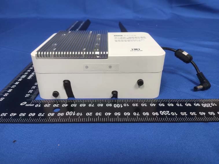
2A8ZSU100STT
May 12, 2023U100 Remote Camera Assistant
Equipment Class
NII - Unlicensed National Information Infrastructure TX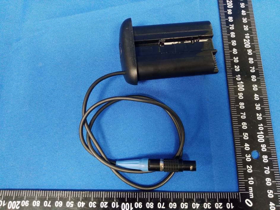
2A8ZSU100IGB
May 12, 2023U100 Remote Camera Assistant
Equipment Class
NII - Unlicensed National Information Infrastructure TX