2A94J-KDH-XM-0016Dashboard
Shenzhen Ningtengda Technology Co., Ltd.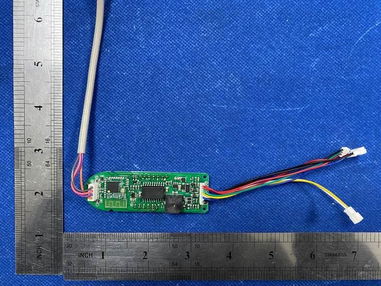
Click to zoom
Application Details
- Equipment Class
- DTS - Digital Transmission System
- Date of Grant
- Jan 31, 2023
- Application Purpose
- Original Equipment
- Date of Application
- Jan 31, 2023
- Equipment Note
- Dashboard
- Frequency Range
- 2402.00000000 - 2480.00000000
- Country
- China
Documents & Files
Document Text
Text extracted from the exhibit documents filed with the FCC. Open a document above to read the original.
Users Manual
product manual Product Name: Dashboard 一、Controller features: quiet, small torque pulsation of motor, low vehicle noise and confortable feeling in driving. Based on the algorithm of field-oriented control (FOC) , the controller has hight efficiency in conversion and can effectively low the temperature of the controller and extend the vehicle endurance. 二、product technical parameter ITEM MINIMUM REGULAR MAXIMUM UNIT REMARKS Operation voltage 30 37 42.5 V Low-voltage 30 - - V Over-Voltage - - 45 V motor current limit - - 16±1 A Static current 10 15 20 uA Closed current 15 20 25 mA Operation temperature -20 50 80 °C Rated Power 350W • Locked-roller protection 3 seconds Sleep time 5minutes cruise control 5 seconds Light power 1W Conversion effeciency ≤80% Eabs <8m Current waveform sine wave Starting mode Non zero start 四、product illustration 1、Power mode: click power on and press for 3 seconds to power off 2、Gear shift: double click to change gear 3、LED light: click the button to turn on the headlights when the machine is on and click again to turn off the headlights 4、 Brake Tail light:The tail light is always on when the headlight is on and flashes while braking. 5、 Gear speed limits: lower speed, 15km/h, middle speed 20km/h high speed 25km/h; 6、 Enter cruise: First, turn on cruise control at the APP end, turn the handle stably for 5 seconds in the riding state and enter cruise control mode without change, and the buzzer emits a sound; 7、 Exit cruise: turn the knob again or press the brake to exit cruise in cruise mode; 8、 Handle voltage: the handle voltage range is 0.8V-4.2V; 9、 Low voltage indication: When the battery power is too low, the power symbol flashes. 五、connecting-port description Controller battery base XT30_3.6mm black straight male plug base Controller motor base 6.3mm Flip chip Battery communication base 2.0mm 3PIN connection base Instrument communication 2.0mm 4PIN connection base base Instrument brake line Connection port:3P male line length: 85mm Instrument turn line Connection port:3P female line length: 85mm Instrument headlight line Connection port:2P male line length: 85mm FCC Warnning: This equipment has been tested and found to comply with the limits for a Class B digital device, pursuant to part 15 of the FCC Rules. These limits are designed to provide reasonable protection againstharmful interference in a residential installation. This equipment generates, uses and can radiateradio frequency energy and, if not installed and used in accordance with the instructions, maycause harmful interference to radio communications. However, there is no guarantee thatinterference will not occur in a particular installation. If this equipment does cause harmfulinterference to radio or television reception, which can be determined by turning the equipmentoff and on, the user is encouraged to try to correct the interference by one or more of thefollowing measures: • Reorient or relocate the receiving antenna. • Increase the separation between the equipment and receiver. • Connect the equipment into an outlet on a circuit different from that to which the receiver is connected. • Consult the dealer or an experienced radio/TV technician for help. Caution: Any changes or modifications to this device not explicitly approved by manufacturer could void your authority to operate this equipment. This device complies with part 15 of the FCC Rules. Operation is subject to the following two conditions: (1)This device may not cause harmful interference, and (2) this device must accept any interference received, including interference that may cause undesired operation. This equipment complies with FCC radiation exposure limits set forth for an uncontrolled environment. This equipment should be installed and operated with minimum distance 0cm between the radiator and your body.
External Photos
FCC ID: 2A94J-KDH-XM-0016 External Photos of the EUT Photo 1 Photo 2 Photo 3 FCC ID: 2A94J-KDH-XM-0016 Photo 4 Photo 5 Photo 6 FCC ID: 2A94J-KDH-XM-0016 Photo 7
ID Label/Location Info
Label and Location Size: L: 1.5.0cm*W: 0.5cm Label and Location FCC ID : 2A94J-KDH-XM-0016
Internal Photos
FCC ID: 2A94J-KDH-XM-0016 Internal Photos of the EUT Photo 1 Photo 2 BLE PCB Antenna
RF Exposure Info
RF Exposure evaluation FCC ID: 2A94J-KDH-XM-0016 1.1. Applicable Standard According to §1.1307(b)(1), systems operating under the provisions of this section shall be operated in a manner that ensures that the public is not exposed to radio frequency energy level in excess of the Commission’s guidelines. According to §1.1310 and §2.1093 RF exposure requirement KDB447498 v06: Mobile and Portable Devices RF Exposure Procedures and Equipment Authorization Policies 1.2. Requirement According to KDB447498 D01 General RF Exposure Guidance v06 Section 4.3.1 Standalone SAR test exclusion considerations: “Unless specifically required by the published RF exposure KDB procedures, standalone 1-g head or body and 10-g extremity SAR evaluation for general population exposure conditions, by measurement or numerical simulation, is not required when the corresponding SAR Test Exclusion Threshold condition, listed below, is satisfied. These test exclusion conditions are based on source-based time-averaged maximum conducted output power of the RF channel requiring evaluation, adjusted for tune-up tolerance, and the minimum test separation distance required for the exposure conditions.22 The minimum test separation distance is determined by the smallest distance from the antenna and radiating structures or outer surface of the device, according to the host form factor, exposure conditions and platform requirements, to any part of the body or extremity of a user or bystander (see 5) of section 4.1). To qualify for SAR test exclusion, the test separation distances applied must be fully explained and justified by the operating configurations and exposure conditions of the transmitter and applicable host platform requirements, typically in the SAR measurement or SAR analysis report, according to the required published RF exposure KDB procedures. When no other RF exposure testing or reporting is required, a statement of justification and compliance must be included in the equipment approval, in lieu of the SAR report, to qualify for the SAR test exclusion. When required, the device specific conditions described in the other published RF exposure KDB procedures must be satisfied before applying these SAR test exclusion provisions; for example, handheld PTT two-way radios, handsets, laptops & tablets etc.23 “ [(max. power of channel, including tune-up tolerance, mW)/ (min. test separation distance, mm)] · [√f (GHz)] ≤ 3.0 for 1-g SAR and ≤ 7.5 for 10-g extremity SAR, where: • f (GHz) is the RF channel transmit frequency in GHz • Power and distance are rounded to the nearest mW and mm before calculation • The result is rounded to one decimal place for comparison • 3.0 and 7.5 are referred to as the numeric thresholds in the step 2 below The test exclusions are applicable only when the minimum test separation distance is ≤ 50 mm and for transmission frequencies between 100 MHz and 6 GHz. When the minimum test separation distance is < 5 mm, a distance of 5 mm according to 5) in section 4.1 is applied to determine SAR test exclusion. 1.3. Manufacturing tolerance GFSK (Peak) Channel Channel 0 Channel 19 Channel 39 Target (dBm) 0.0 0.0 0.0 Tolerance ±(dB) 1.0 1.0 1.0 Page 2 of 2 2. E v a l u a t i o n R e s u l t Evaluation Results Band/Mode f (GHz) Antenna Distance (mm) RF output power (including tune-up tolerance) SAR Test Exclusion Threshold SAR Test Exclusion dBm mW BT 2.450 5 1.0 1.2589 0.3941<3.0 Yes 3. C o n c l u s i o n The measurement results comply with the FCC Limit per 47 CFR 2.1093 for the uncontrolled RF Exposure and SAR Exclusion Threshold per KDB 447498 v06 .....................End of Report.........................
Test Report
1. Antenna Description: Antenna type PCB antenna Model KDH-M4-001 Frequency range 2400-2500MHz Manufacturer Shenzhen Kaidihui Technology Co., Ltd. ANT Peak Gain 1.50 dBi 2. Antenna Photo: 3. Test Equipment & Conditions Length :10.73mm Width:4.30mm 3.1 Test instrument VSWR is tested using Agilent E5071B connected to a hand mechanism, and the status is free space. 3.2 Test environment and methods 4.Antenna Radiation Pattern 2400MHz 2450MHz 2500MHz
Test Report
Shenzhen CTA Testing Technology Co., Ltd. Room 106, Building 1, Yibaolai Industrial Park, Qiaotou Community, Fuhai Street, Bao‘an District, Shenzhen, China Shenzhen CTA Testing Technology Co., Ltd. Room 106, Building 1, Yibaolai Industrial Park, Qiaotou Community, Fuhai Street, Bao’an District, Shenzhen, China Tel:+86-755 2322 5875 E-mail:[email protected] Web:http://www.cta-test.cn FCC PART 15 SUBPART C TEST REPORT FCC PART 15.247 Report Reference No. ..................... : FCC ID. ............................................ : CTA22112801001 2A94J-KDH-XM-0016 Compiled by ( position+printed name+signature) .. : File administrators Zoey Cao Supervised by ( position+printed name+signature) .. : Project Engineer Amy Wen Approved by ( position+printed name+signature) .. : RF Manager Eric Wang Date of issue ..................................... : Dec. 21, 2022 Testing Laboratory Name .............. : Shenzhen CTA Testing Technology Co., Ltd. Address ............................................ : Room 106, Building 1, Yibaolai Industrial Park, Qiaotou Community, Fuhai Street, Bao‘an District, Shenzhen, China Applicant’s name ............................ : Shenzhen Ningtengda Technology Co., Ltd. Address ............................................ : 1001Room, Office Premises, Fuji Zhidi Building, Longgang Road 6018th, Longgang Street, Longgang District, Shenzhen, CN. Test specification ...........................: Standard ........................................... : FCC Part 15.247 Shenzhen CTA Testing Technology Co., Ltd. All rights reserved. This publication may be reproduced in whole or in part for non-commercial purposes as long as the Shenzhen CTA Testing Technology Co., Ltd. is acknowledged as copyright owner and source of the material. Shenzhen CTA Testing Technology Co., Ltd. takes no responsibility for and will not assume liability for damages resulting from the reader's interpretation of the reproduced material due to its placement and context. Equipment description...................: Dashboard Trade Mark ....................................... : N/A Manufacturer .................................... : Shenzhen Kaidihui Technology Co., Ltd. Model/Type reference....................... : KDH-XM-0016 Listed Models .................................. : See P2 for details Modulation ....................................... : GFSK Frequency .......................................... From 2402MHz to 2480MHz Ratings ............................................. : DC 36.0V from battery and DC 5.0V from external circuit Result................................................ : PASS Report No.: CTA22112801001 Page 2 of 31 Shenzhen CTA Testing Technology Co., Ltd. Room 106, Building 1, Yibaolai Industrial Park, Qiaotou Community, Fuhai Street, Bao’an District, Shenzhen, China Tel:+86-755 2322 5875 E-mail:[email protected] Web:http://www.cta-test.cn T E S T R E P O R T Equipment under Test : Dashboard Model /Type : KDH-XM-0016 Listed Models : KDH-M4-002, KDH-M4-003, KDH-M4-010, KDH-M4-040, KDH-S1-001, KDH-S1-002, KDH-S1-004, KDH-S1-040, KDH-S1-041, KDH-S1-042, KDH-G-001, KDH-G-002, KDH-G-003, KDH-G2-001, KDH-G2-003, KDH-G2-004, KDH-MAX-001, KDH-MAX-002, KDH-MAX-046, KDH-MAX-047, KDH-MAX-066, KDH-MAX-067-01, KDH-102, KDH-103, KDH-124, KDH-125, KDH-ES-001, KDH-ES-002, KDH-ES-003, KDH-ES-019, KDH-ES-020, KDH-ES-050, KDH-02-087, KDH-02-088, KDH-02-089, KDH-02-090, KDH-02-091, KDH-XM-0010, KDH-XM-0011, KDH-XM-0012, KDH-XM-0016, KDH-XM-0018, KDH-XM-0022, KDH-XM-0023, KDH-XM-0024, KDH-XM-0026, KDH-XM-0193, KDH-XM-0194, KDH-XM-0195, KDH-XM-0196, KDH-XM-0197, KDH-XM-0198, KDH-XM-0198-01, KDH-XM-0199, KDH-XM-0200, KDH-XM-0201, KDH-XM-0202, KDH-F30-001, KDH-F30-004 Applicant : Shenzhen Ningtengda Technology Co., Ltd. Address : 1001Room, Office Premises, Fuji Zhidi Building, Longgang Road 6018th, Longgang Street, Longgang District, Shenzhen, CN. Manufacturer : Shenzhen Kaidihui Technology Co., Ltd. Address : No.1, Hongling Second Road, Liulian Community, Pingdi Street, Longgang District, Shenzhen, CN. Test Result: PASS The test report merely corresponds to the test sample. It is not permitted to copy extracts of these test result without the written permission of the test laboratory. Report No.: CTA22112801001 Page 3 of 31 Shenzhen CTA Testing Technology Co., Ltd. Room 106, Building 1, Yibaolai Industrial Park, Qiaotou Community, Fuhai Street, Bao’an District, Shenzhen, China Tel:+86-755 2322 5875 E-mail:[email protected] Web:http://www.cta-test.cn Contents 1 T E S T S T A N D A R D S ................................................................. 4 2 S U M M A R Y ............................................................................ 5 2.1 General Remarks 5 2.2 Product Description 5 2.3 Equipment Under Test 5 2.4 Short description of the Equipment under Test (EUT) 5 2.5 EUT operation mode 6 2.6 Block Diagram of Test Setup 6 2.7 Related Submittal(s) / Grant (s) 6 2.8 Modifications 6 3 T E S T E N V I R O N M E N T .............................................................. 7 3.1 Address of the test laboratory 7 3.2 Test Facility 7 3.3 Environmental conditions 7 3.4 Summary of measurement results 8 3.5 Statement of the measurement uncertainty 8 3.6 Equipments Used during the Test 9 4 T E S T C O N D I T I O N S A N D R E S U L T S ........................................... 10 4.1 AC Power Conducted Emission 10 4.2 Radiated Emissions and Band Edge 11 4.3 Maximum Peak Output Power 18 4.4 Power Spectral Density 19 4.5 6dB Bandwidth 21 4.6 Out-of-band Emissions 23 4.7 Antenna Requirement 27 5 T E S T S E T U P P H O T O S O F T H E E U T ......................................... 28 6 P H O T O S O F T H E E U T ........................................................... 29 Report No.: CTA22112801001 Page 4 of 31 Shenzhen CTA Testing Technology Co., Ltd. Room 106, Building 1, Yibaolai Industrial Park, Qiaotou Community, Fuhai Street, Bao’an District, Shenzhen, China Tel:+86-755 2322 5875 E-mail:cta@cta-test…
Text truncated - open the document above for the full version.
Test Setup Photos
FCC ID: 2A94J-KDH-XM-0016 Test Setup Photos of the EUT
Contact Information
Applicant
Stone Jiang
Test Firm
SHENZHEN CTA TESTING TECHNOLOGY CO., LTD.Eric Wang
[email protected]+86 755 2322 5875
Technical Specifications
| # | Rule Parts | Frequency Range | Power Output |
|---|---|---|---|
| 1 | 15C | 2.40 GHz - 2.48 GHz | 1.20 mW |
Other Applications from Shenzhen Ningtengda Technology Co., Ltd.
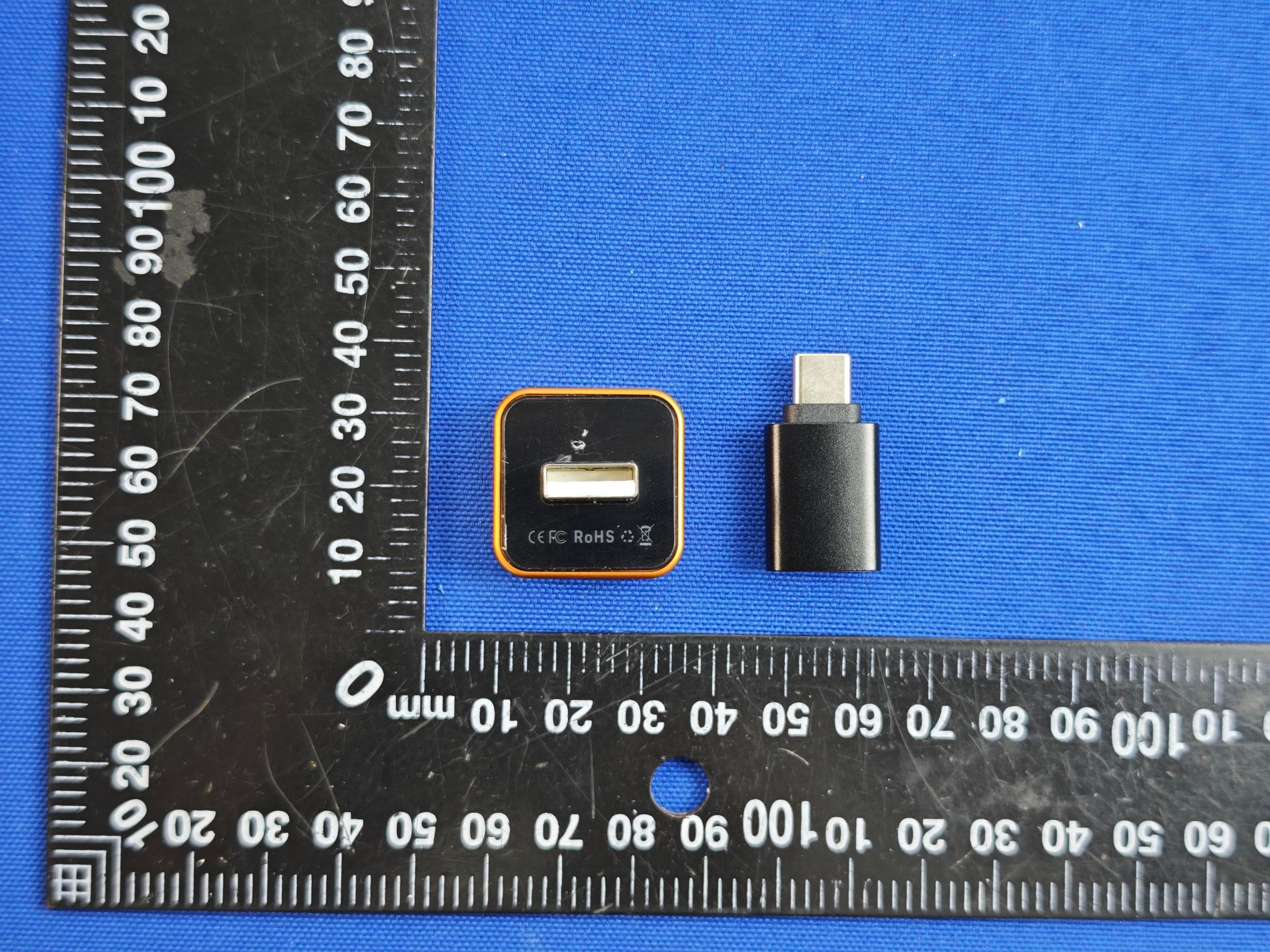
2A94J-CP027
Jun 11, 2026USB wireless adapter
Equipment Class
NII - Unlicensed National Information Infrastructure TX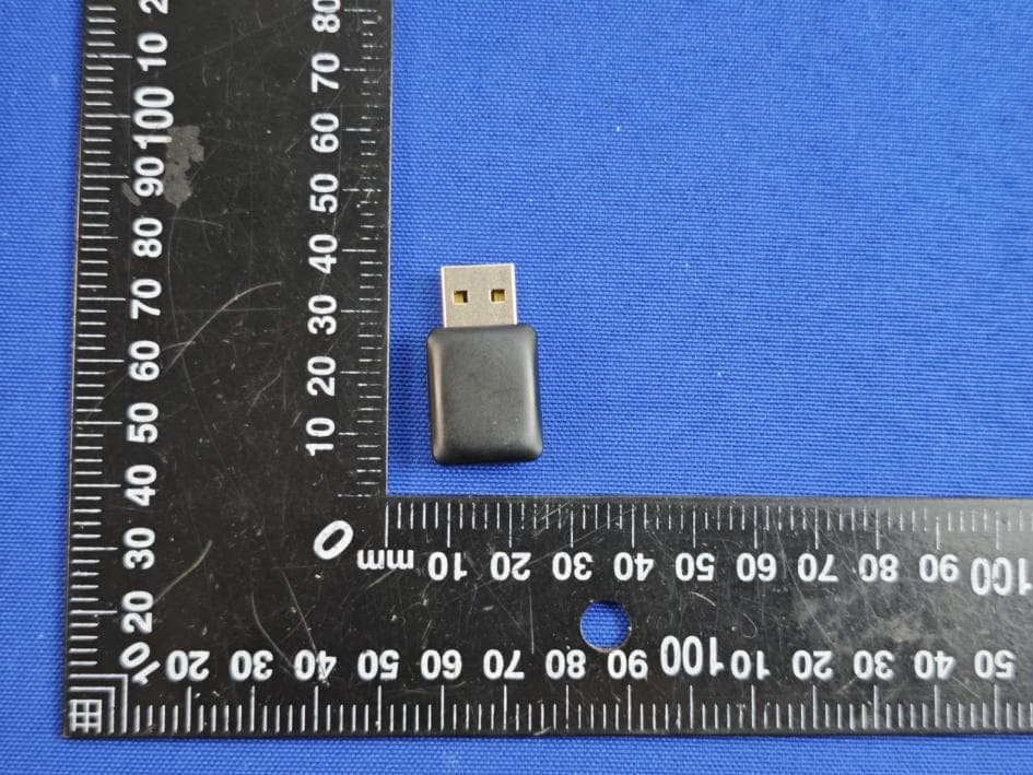
2A94J-CP025
Jun 11, 2026USB wireless adapter
Equipment Class
DTS - Digital Transmission System